Map sensor ACURA INTEGRA 1998 Service User Guide
[x] Cancel search | Manufacturer: ACURA, Model Year: 1998, Model line: INTEGRA, Model: ACURA INTEGRA 1998Pages: 1680, PDF Size: 53.14 MB
Page 241 of 1680
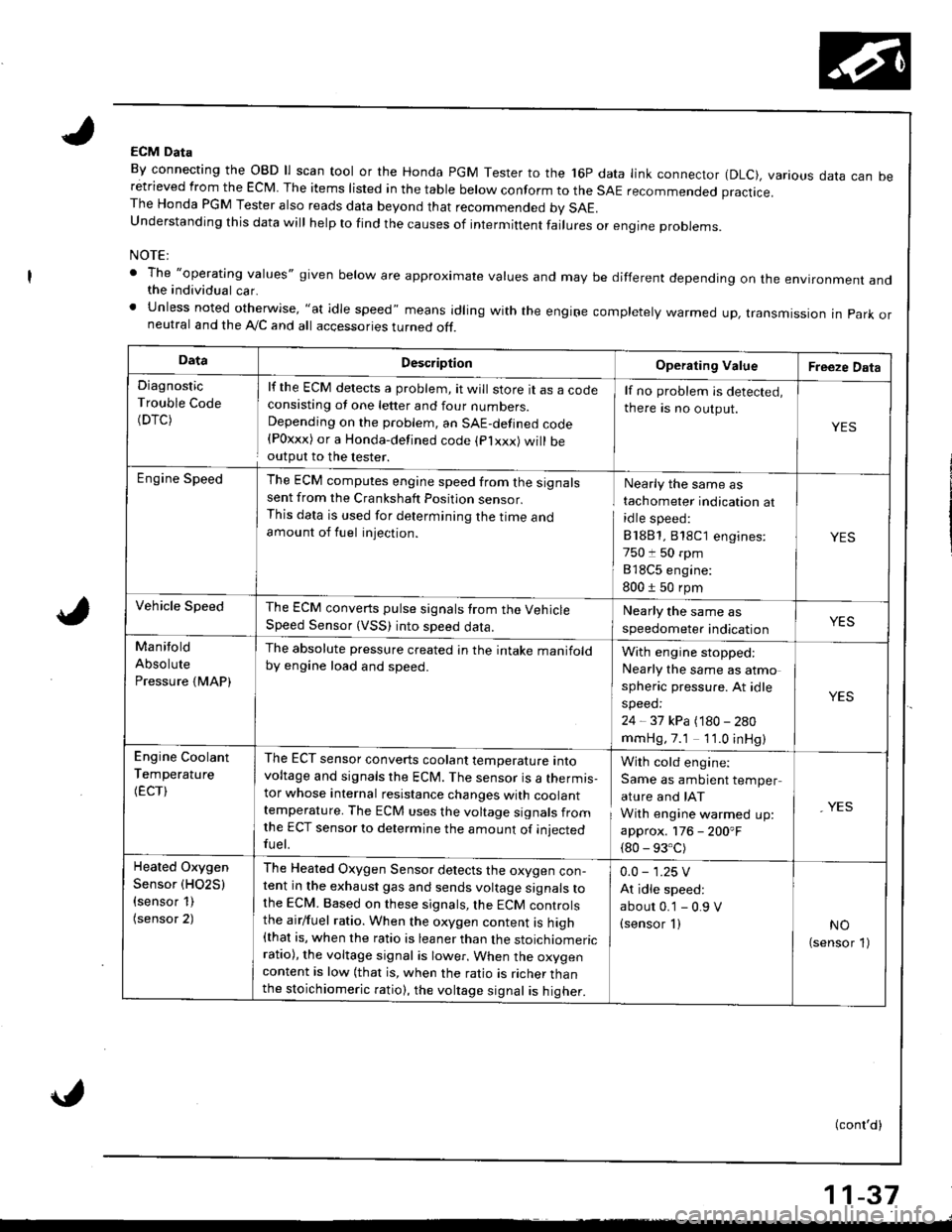
ECM Data
By connecting the OBD ll scan tool or the Honda PGM Tester to the 16P data link connector (DLC), various data can beretrieved from the EcM The items risted in the tabre berow conform to the sAE recommended practice.The Honda PGM Tester also reads data beyond that recommended bv SAE.understanding this data wirl herp to rind the causes of intermiftent fairures or engine probrems.
NOTE:
' The "operatlng values" given below are approximate values and may be different depending on the environment andthe individual car.' Unless noted otherwise, "at idle speed" means idling with the engiFe completely warmed up, transmissron in park orneutral and the A,/C and all accessories turned off.
DataDescriptionOperating ValueFreeze Data
Diagnostic
Trouble Code(DTC)
lf the ECM detects a problem, it will store tt as a cocteconsisting ot one letter and four numbers.Depending on the problem, an SAE-defined code{Poxxx) or a Honda-defined code (plxxx) will beoutput to the lester.
lf no problem is detected,
there is no output.
YES
Engine SpeedThe ECM computes engine speed from the signalssent from the Crankshaft Position sensor.This data is used for determining the I|me andamount of fuel injection.
Nearly the same as
tachometer indication at
idle speed:
81881,818C1 engines:
750 t 50 rpm
818C5 engine:
800 1 50 rpm
YES
Vehicle SpeedThe ECM converts pulse signals trom the VehicleSpeed Sensor (VSS) into speed data.
Nearly the same as
speedometer indicationYES
Manitold
Absolute
Pressure {MAP)
The absolute pressure created in the intake manifoldby engine load and speed.With engine stopped:
Nearly the same as atmo
spheric pressure. At idle
speed:
24 - 37 kPa (180 - 280
mmHg,7.1 1'1.0 inHg)
YES
Engine Coolant
Temperature
(ECT)
The ECT sensor converts coolant temperature intovoltage and signals the ECM. The sensor is a thermis-tor whose internal resistance changes with coolanttemperature. The ECM uses the voltage signals fromlhe ECT sensor to determine the amount of iniectedfuel.
With cold engine:
Same as ambient temper
ature and IAT
With engine warmed up:
approx. 176 - 200'F
{80 - 93.C)
, YES
Heated Oxygen
Sensor (HO2S)
{sensor 1)(sensor 2)
The Heated Oxygen Sensor detects the oxygen con-tent in the exhaust gas and sends voltage signals tothe ECM. Based on these signals,lhe ECM controlsthe airlfuel ratio. When the oxygen content is high{that is, when the ratio is leaner than the stoichiomericratio), the voltage signal is lower. When the oxygencontent is low (that is, when the ratio is richer thanthe stoichiomeric ratio), the voltage signal is higher.
0.0 - 1.25 V
At idle speed:
abour 0.'1 - 0.9 V(sensor I )NO(sensor 1)
(conl'd)
11-37
Page 242 of 1680
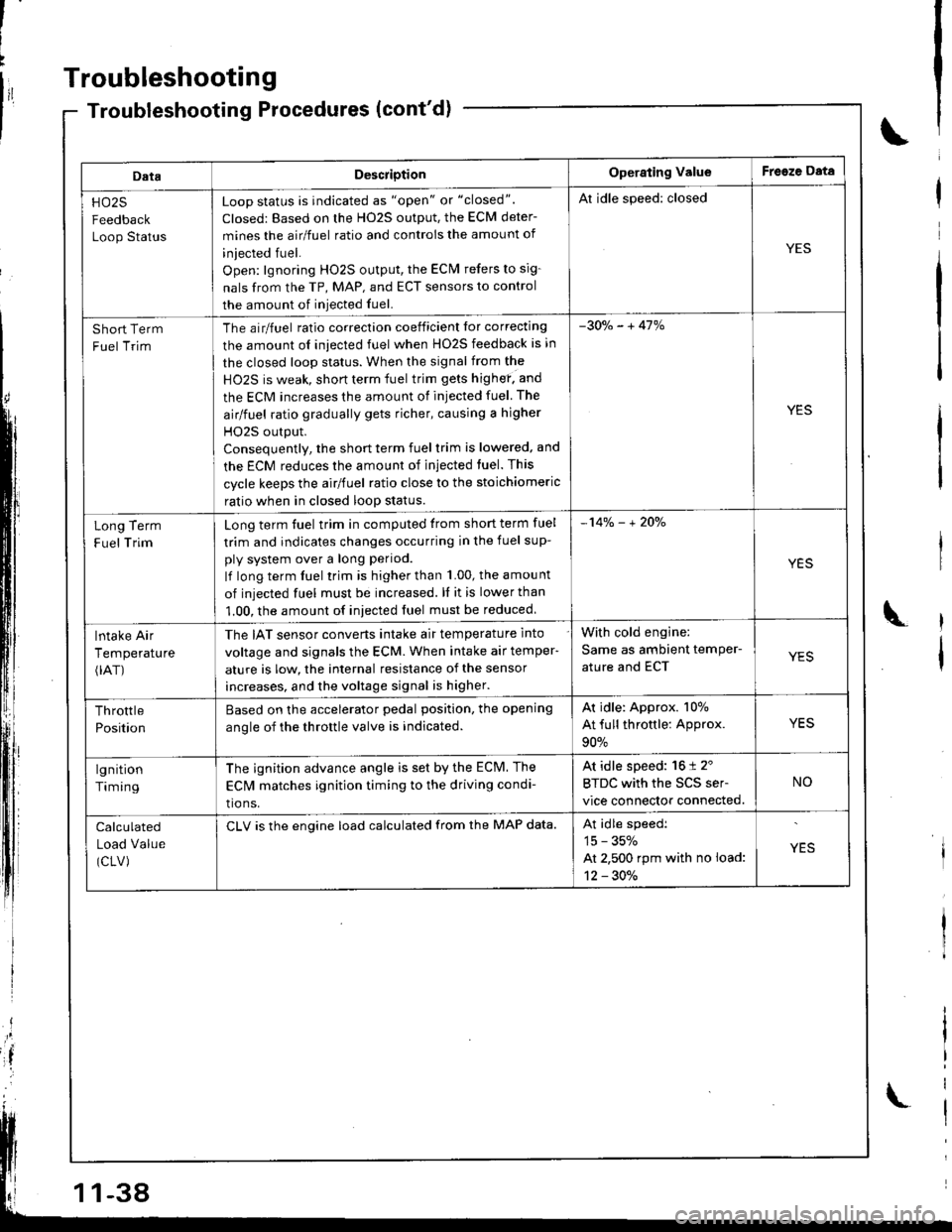
Troubleshooting
DataDescriotionOperating ValueFreeze Data
HO25
Feedback
Loop Status
Loop status is indicated as "open" or "closed".
Closed: Based on the H02S output, the ECM deter-
mines the airlfuel ratio and controis the amount of
iniected fuel.
Open: lgnoring HO2S output, the ECM refers to sig-
nals from the TP, MAP, and ECT sensors to control
the amount of iniected fuel.
Al idle speed: closed
YES
Short Term
Fuel Trim
The airlfuel ratio correclion coeificient lor correcting
the amount ol iniected fuel when HO2S feedback is in
the closed loop status. When the signal from the
HO2S is weak, short term fuel trim gets highef. and
the ECM increases the amount of injected fuel The
airlfuel ratio gradually gets richer, causing a higher
HO2S output.
Consequentlv, the short term fuel trim is lowered, and
the ECM reduces the amount of injected tuel. This
cycle keeps the airlfuel ratio close to the stoichiomeric
ratio when in closed loop status.
-30o/" - + 41%
YES
Term
Trim
Long
F uel
Long term fuel trim in computed trom short term fuel
trim and indicates changes occurring in the fuel sup-
ply system over a long period.
lf long term fuel trim is higher than 1.00, the amou nt
of injected fuel must be increased. ll it is lower than
1.00, the amount of iniected fuel must be reduced
-14% - + 2Oo/"
YES
lntake Air
Temperature(rAT)
The IAT sensor converts intake air temperature into
voltage and signals the ECM. When intake air temper-
ature is low, the internal resistance of the sensor
increases, and the voltage signal is higher.
With cold engine:
Same as ambient temPer-
ature and ECTYES
Throttle
Position
Based on the accelerator pedal position. the opening
anole of the throttle valve is indicated.
Ar idle: Approx. 107o
At full throttle: Approx.
90%
YES
lgnition
Timing
The ignition advance angle is set by the ECM. The
EClvl matches ignition timing to the driving condi-
tio ns.
At idle speed: 16 t 2'
BTDC with the SCS ser-
vice connector connected.
NO
Calculated
Load Value
(CLV)
CLV is the engine load calculated from the MAP data.At idle speedi
15 - 35%
At 2,500 rpm with no load:
12 - 30./.
YES
-38
Page 245 of 1680
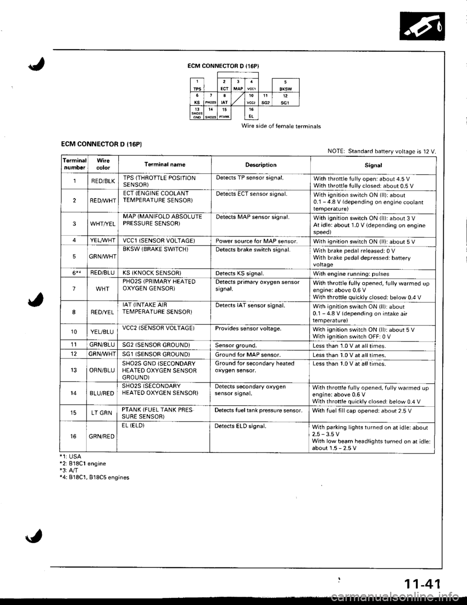
ECM CONNECTOR D (16P}
Wire side of female terminals
ECM CONNECTOR D (16P1NOTE| Standard battery voltage is 12 V.
TerminalnumberWirecolorT6rminal nameDoscriptionSignal
1RED/BLKTPS (THROTTLE POSITIONSENSOR)Detects TP sensor s;gnal.With throttle fully open: about 4.5 VWith throttle fully closed: about 0.5 V
2REDAr'r'HTECT (ENGINE COOLANTTEMPERATUBE SENSOB}Detects ECT sensor signal.With ignition switch ON (ll)r about0.1 - 4.8 V (depending on engine coolanttemperalure)
3WHT//ELMAP {MANIFOLD AESOLUTEPBESSURE SENSOR)Detects MAP sensor signal.With ignition switch ON (ll)iabout 3 VAt idle: about 1.0 V {depending on enginespeeol
4YELA/VHTvccl{SENSOR VOLTAGE)Power source for MAP sensor,With ignition switch ON (ll): about 5 V
5GRNAVHTBKSW (BRAKE SWITCH)Detects brake switch signal.With brake pedal released: 0 VWith brake pedal depressed: batteryvoltage
6*!RED/BLUKS (KNOCK SENSOR}Detects KS signal.With engine running: pulses
lPHO2S (PRIMARY HEATEDOXYGEN GENSOR)Detects primary oxygen sensorsignal.With throttle fully opened, fully warmed upengine: above 0.6 VWith throttle quickly closed: below 0.4 V
8RED/VEL
IAT (INTAKE AIRTEMPERATURE SENSOR)Detects IAT sensor signal.With ignition switch ON {ll): about0.1 - 4.8 V (depending on intake airtemperature)
10YEL/BLUvcc2(SENSOB VOLTAGE)Provides sensor voltage,With ignition switch ON (ll): about 5 VWith ignition switch OFF: 0 V
1lGRN/8LUSG2 (SENSOR GROUND}Sensor ground.Less than 1.0 V at all times.
GFNA/VHT(SENSOR GROUND}Ground tor MAP sensor.Less than 1.0 V at all times.
OBN/BLUSHO2S GND (SECONDARY
HEATED OXYGEN SENSORGROUND)
Ground for secondary heatedoxygen sensor,Less than 1.0 V at alltimes.
148LU/REDSH02S (SECONDARY
HEATED OXYGEN SENSOR}Detects secondary oxygensensor srgnal.With throttle fully opened. fully warmed upengine: above 0,6 VWith throttle quickly closed: below 0.4 V
LT GRNPTANK (FUEL TANK PRESSURE SENSOR)Detects fueltank pressure sensor.With luel fill cap opened: about 2-5 V
GRN/RED
EL (ELOiDetects ELD signal.With parking lights turned on at idle: about2.5 -3.5 VWith low beam headlights turned on at idle:about 1.5 - 2.5 V*1:USA*2: 818C1 engine"3:A"/T*4: B18C'1, 818C5 engines
11-41
Page 246 of 1680
 with the SCS service connector
connected.
Ia
\
\
il
\
DT")
1l
Troubleshooting
Diagnostic Trouble Gode (DTCI Chart
*: These DTCS will be indicated by the blinking ot the lvalfunction Indicator Lamp (MlL) with the SCS service connector
connected.
Ia
\
\
il
\
DTC
lMlL indication*lDetection ltemProbabls CausePage
P0107 (3)
Manifold Absolute
Pressure Circuit
Low Input
Open or short in MAP sensor circuit
MAP sensor
ECM
'11-54
P0108 (31
Manifold Absolute
Pressure Circuit
High Input
Open in MAP sensor circuit
MAP sensor
ECM
tt-5t,
P0112 (10)
Intake Air
Temperature Circuit
Low Input
Short in IAT sensor circuit
IAT sensor
ECM
11.58
P0113 {10)
lntake Air
Temperature Circuit
High Input
Open in IAT sensor circuit
IAT sensor
ECM
1'1-59
P0116 (86)
Engine Coolant
Temperature Circuit
Range/Performance Problem
. ECT sensor' Cooling system11-60
P0117 (6)
Engine Coolant
Temperature Circuit
Low Input
Short in ECT sensor circuit
ECT sensor
ECM
1 't-61
P0118 {6)
Engine Coolant
Temperature Circuit
High Input
Open in ECT sensor circuit
ECT sensor
ECt\,4
1't -62
P0122l7l
Throttle Position
Circuit
Low Input
Open or shon in TP sensor circuit
TP sensor
ECM
11,63
P0123 (7)
Throttle Position
Circuit
High Input
Open in TP sensor circuit
TP sensor
ECM
I t-oc
P0131 (1 )
Primary Heated Oxygen Sensor
Circuit Low Voltage (Sensor 1)
Shon in Primary HO2S (Sensor'l) circuit
Primary H02S {Sensor 1)
Fuel supply system
ECM
11-67
P0132 (1)Primary Heated Oxygen Sensor
Circuit High Voitage (Sensor 1)
Open in Primary HO2S (Sensor 1) circuit
Primary HO2S (Sensor 1)
ECM
11-69
P0133 (61)Primary Heated Oxygen Sensor
Slow Response (Sensor 1)
. Primary HO2S (Sensor 1). Exhaust system1 1-70
,r:' 11-42
L
Page 247 of 1680
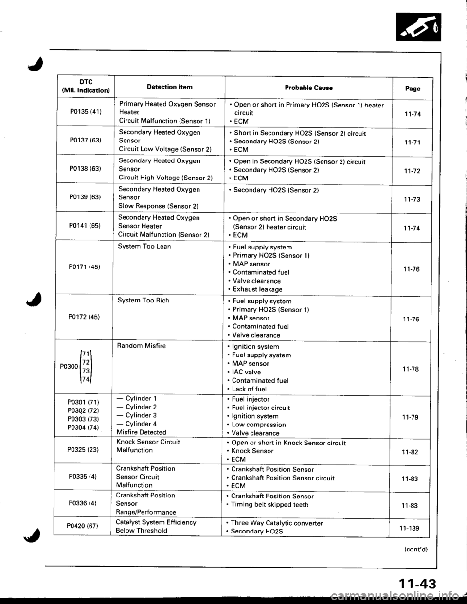
DTC(MlL indicationlDeteciion ltemProbable CausoPage
P013s {41)
Primary Heated Oxygen Sensor
Heater
Circuit Malfunction {Sensor '1)
. Open or shon in Primary HO2S (Sensor 1) heater
circuit. ECM1't-74
P0137 (63)Secondary Heated Oxygen
Sensor
Circuit Low Voltage (Sensor 2)
Short in Secondary HO2S (Sensor 2) circuit
Secondary H02S {Sensor 2)
ECM11-7'l
P0138 {63)
Secondary Heated Oxygen
Sensor
Circuit High Voltage (Sensor 2)
Open in Secondary HO2S (Sensor 2) circuit
Secondary HO2S (Sensor 2)
ECM
P0139 (63)Secondary Heated Oxygen
Sensor
Slow Response (Sensor 2)
Secondary HO2S (Sensor 2)
P0141 (651Secondary Heated Oxygen
Sensor Heater
Circuit Malfunction (Sensor 2)
. Open or short in Secondary HO2S(Sensor 2) heater circuit. ECM11-'14
P0171 (45)
System Too LeanFuel supply system
Primary HO2S {Sensor I )MAP sensor
Contaminated fuel
Valve clearance
Exhaust leakage
11-76
P0172 t45l
System Too RichFuel supply system
Primary HO2S (Sensor 1)
MAP sensor
Contaminated fuel
Valve clearance
11.76
,...,{iil
174l
Random Misfirelgnition system
Fuel supply system
MAP sensor
IAC valve
Contaminated fuel
Lack offuel
't 1-78
P0301 (71)
P03Q2 l'121
P0303 (73)
P0304 (74)
- Cylinder 1- Cylinder 2- Cylinder 3- Cylinder 4
Misfire Detected
Fuel injector
Fuel injector circuit
lgnition system
Low compression
Valve clearance
11-79
P0325 {23)
Knock Sensor Circuit
MalfunctionOpen or short in Knock Sensor circuit
Knock Sensor
ECM11-82
P0335 (4)Crankshaft Position
Sensor Circuit
Malfunction
Crankshaft Position Sensor
Crankshaft Position Sensor circuit
ECM1 1-83
P0336 (4)Crankshaft Position
Sensor
Range/Performance
. Crankshaft Position Sensor. Timing belt skipped teethIl-83
P0420 (67)Catalyst System Efficiency
Below Threshold
. Three Way Catalytic converter. Secondary HO2S11-139
(cont'd)
11-43
Page 248 of 1680
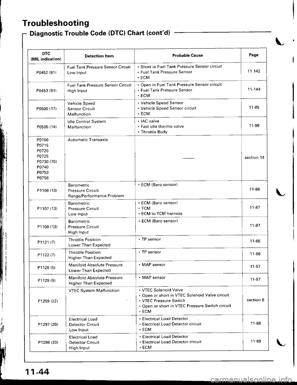
Troubleshooting
Diagnostic Trouble Code (DTCI Chart (cont'd)
L
DTC
(MlL indication)Detection ltemProbable CausePage
P0452 (91)FuelTank Pressure Sensor Circuit
Low lnput
Short in Fuel Tank Pressure Sensor circuit
Fuei Tank Pressure Sensor
ECM
11 142
P0453 (91)Fuel Tank Pressure Sensor Circuit
High Input
Open in Fuel Tank Pressure Sensor circuit
Fuel Tank Pressure Sensor
ECrVI
11-144
P0500 {17}
Vehicle Speed
Sensor Circuit
Malfunction
Vehicle Speed Sensor
Vehicle Speed Sensor circuit
ECM
11-85
P0505 (14)ldle Control System
Malfunction
IAC valve
Fast idle thermo valve
Th rottle Body
'11-98
P0700
P0715
P0120
P0125
P0730 (70)
P0740
P0753
P0758
Automatic Transaxle
section'14
Pl106 (13iBarometric
Pressure Circuit
Range/Performance Problem
. ECM (Baro sensor)1'l -86
P1107 (']3)Barometric
Pressure Circuit
Low lnput
ECM (Baro sensor)
TCM
ECM to TCM harness
11-87
P1'108 (13)Ba ro metric
Pressure Circuit
High Input
ECM (Baro sensor)11-41
P1121 \11Throttle Position
Lower Than Expected
. TP sensor
P112211JThrottle Position
H igher Than Expected
'TP sensor
P1 't 28 (5)Manifold Absolute Pressure
Lower Than Expected
. MAP sensor11,57
P1129 (5)Manilold Absolute Pressure
Higher Than Expected
. MAP sensor11-57
P1259 \22)
VTEC System MalfunctionVTEC Solenoid Valve
Open or short in VTEC Solenoid Valve circuit
VTEC Pressure Switch
Open or short in VTEC Pressure Switch circuit
ECM
section 6
P1297 (20)Electrical Load
Detector Circuit
Low Input
Electrical Load Detector
Electrical Load Detector circuit
ECM
11-88
P1298 (20)Electrical Load
Detector Circuit
Hig h Input
Electrical Load Delector
Electrical Load Detector circuit
ECM
11-89
-44
Page 252 of 1680
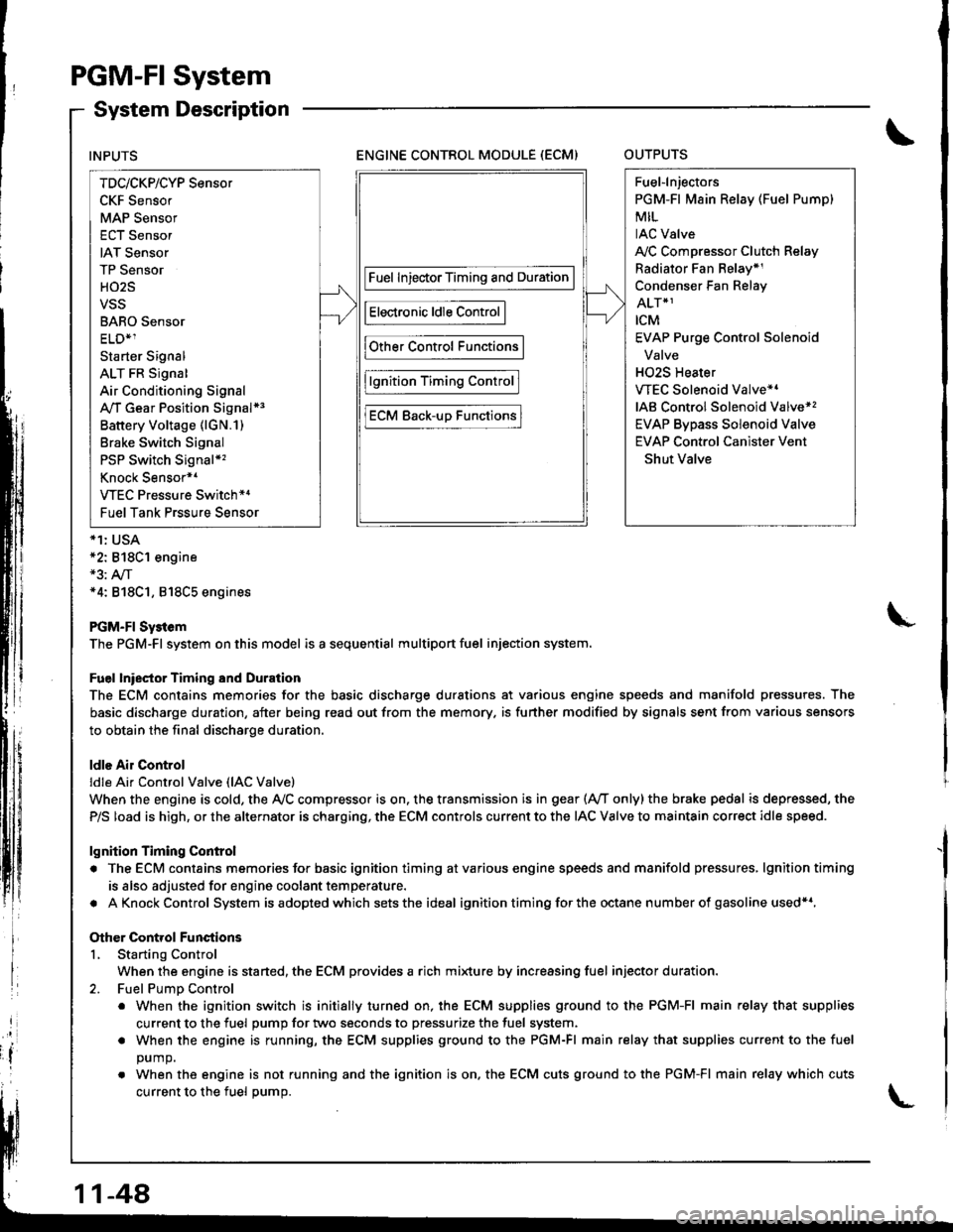
PGM-FI System
System Description
ENGINE CONTROL MODULE (ECM)OUTPUTS
*1: USA*2: 818C1 engine*3: A,/T*4: 818C1, 818C5 engines
PGM-FI Sy3tem
The PGM-Fl system on this model is a sequential multiport fuel injection system.
Fuel lniector Timing and Duration
The ECM contains memories for the basic discharge durations at various engine speeds and manifold pressures. The
basic discharge duration, after being read out from the memory. is further modified by signals sent from various sensors
to obtain the final discharge duration.
ldle Air Control
ldle Ai. Control Valve (lAC Valve)
When the engine is cold, the Ay'C compressor is on. the transmission is in gear (Ay'T only)the brake pedal is depressed, the
P/S load is high, or the alternator is charging, the ECM controls current to the IAC Valve to maintain correct idle speed.
lgnition Timing Control
. The ECM contains memories for basic ignition timing atvarious engine speeds and manifold pressures, lgnitiontiming
is also adjusted for engine coolant temperature.
. AKnockControl System isadoptedwhich sets the ideal ignition timing for the octane n um ber of gasoline used*r,
Other Control Functions
L Starting Control
When the engine is started, the ECM provides a rich mi{ure by increasing fuel injector duration.
2. Fuel PumD Control
. When the ignition switch is initially turned on, the ECM supplies ground to the PGM-FI main relay that supplies
current to the fuel pump for two seconds to pressurize the fuel system.
. When the engine is running, the ECM supplies ground to the PGM-FI main relay that supplies current to the fuel
DUmO.
. When the engine is not running and the ignition is on. the ECM cuts ground to the PGM-FI main relay which cuts
current to the fuel oumo.
INPUTS
TDc/CKP/CYP Sensor
CKF Sensor
MAP Sensor
ECT Sensor
IAT Sensor
TP Sensor
HO2S
VSS
BARO Sensor
ELD*1
Starter Signal
ALT FR Signal
Air Conditioning Signal
A,/T Gear Position Signal*3
Battery Voltage (lGN.1)
Brake Switch Signal
PSP Switch Signal*'
Knock Sensor*1
VTEC Pressure Switch*4
Fuel Tank Prssure Sensor
Fuel InjectorTiming and Duration
Electronic ldle Control
Other Control Functions
lgnition Timing Control
ECM Back-uD Functions
Fuel-lnjectors
PGM-Fl Main Relay (Fuel Pump)
MIL
IAC Valve
A,/C Compressor Clutch Relay
Radiator Fan Belay*1
Condenser Fan Relay
ALT*1
rcM
EVAP Purge Control Solenoid
Valve
H02S Heater
VTEC Solenoid Valve*'
IAB Control Solenoid Valve*,
EVAP Bypass Solenoid Valve
EVAP Control Canister Vent
Shut Valve
11-48
Page 255 of 1680

NOTE:. Whon there is no cod6 stored, the MIL willstay on iftho aorvice check conn€ctor is snoned.' lfthis symptom is intermittent. check tor:- A loos6 Fl E/M (15 A) in the undor-hood tuse/relav box- A loose No. 13 FUEL PUMP {SRS UNIT) (15 A) in th6 under-dash fuse/retay box- An intermitt6nt short in the wir€ betwesn the ECM (C7) and th€ sorvice chock conn€qor- An intormittent open in the wire between the sorvice chsck conneclor and G40l- An intermittent short in the wire betwo€n the ECM (A18) and the gaug6 assemDry- An intermittent shon in the wir6 between the ECM (D14) and the MAP sonsor- An intermittent shon in the wire bstween the ECM (Dto), th6 Tp sensor and Fu6l tankpI6SSU16 SOnSOT- PGM-FI Main relay. See th6 OBD ll scan tool or Honda PGM Tester user's manuals for sp6cific operating instruc-!ons.
(To page 11-52)
(cont'd)
Th. M.lfunction Indic.tor LlmplMlll .t!yr on or comlr on ltt .two aaconda.
Ch.ck th! Dirgnoitic tioubl.Cod. IDTC):'1. Connoct a 6can tool or HondaPGM Tester,2. Turn tho ignition switch ON (ll).3. Read tho DTC with the scantool or Honda PGM T6st6r.
Go to trouHorhooting proQduaaa.
koo p.g6 I 1.3:ll
Ch.ct th. DTC by MIL indication:1. Turn th€ ignition switch OFF.2. Connect the SCS seNic€ con-n€ctor to the sorvico checkconnoctor,3. Turn the ignition s1\,itch ON (ll).
Rapair opan or ahort in wirabotw..n thg ECM lCSl .ndData Llnk Conncctor.Go lo troublcrhootlng pro-c.dur.3. {.co pag. 11-32)
Do.s th6 MIL indicate anv DTC?
Try to start tho engine.
Chack lor r 3hort in th. wlr.3lsqg lln.):1. Turn the ignition switch OFFand turn the ignition switchoN { },2. Disconnect th6 SCS serviceconnector,3. M€a6urg voltaOe between theECM connoctor torminal C7and body ground.
Rapah 3hort to body ground inlh. wir. b.lw..n ECM lCTl .ndacwica chack connactor.
ls ther6 approx. 5 V?
\{,
(To page 11-52)
11-51
Page 256 of 1680

Choc* tol s short in tho wir6 lMlLlino):1. Turn the ignition switch OFF.2. Disconn€ct the ECM conn6c-tor A (32P).
3. Turn the i")
PGM.FISystem
Gontrol Module (ECMI (cont'dlEngine
\
L
(From page 11-51)
Choc* tol s short in tho wir6 lMlLlino):1. Turn the ignition switch OFF.2. Disconn€ct the ECM conn6c-tor A (32P).
3. Turn the ignition switch ON (ll).
Repair 3hon to body ground in
rhe wire bstw.on tho ECM (A181
and MlL.
Substituto s known-good ECMend rechock. H 3ymptom/indica-tion goes awry, replacc tho origi-nelECM,
{From page 11-51)
Inspect Fl E/M (15 A) fuse in theunder-hood Iuse/relay box.
- Ropsir short in tha wircbotw.on Fl E/M {'15 Al tu3c'rnd PGM-FI m.in t.lry.- Rool.c. Fl E/M l15A)tu!€.
Inspect No. 13 FUEL PUMP (SRS
UNIT) ('l5A) fuse in the undeFdash fuse/relay box.
- Reo.ir sholt in th. wirobotw..n No. 13 FUEL PUMP
{SRs UNIT) (15 Al fur..ndFGM-FI m.in rclay.- Repl.co No. 13 FUEL PUMP(SRS UNIT) {15 Alturr.
Ch6ck for . shon in a son3or1. Turn the ignition switch ON (ll).
2. Disconnect the 3P connectorfrom oach sensor one at time:. MAP sensor. TP sensor. Fueltank pressure sensor
Rapl.cc tha 3onaor thrt cauaadihe light to 9o out.Does the MIL go OFF?
1-52
(To page 11-53)
Page 257 of 1680
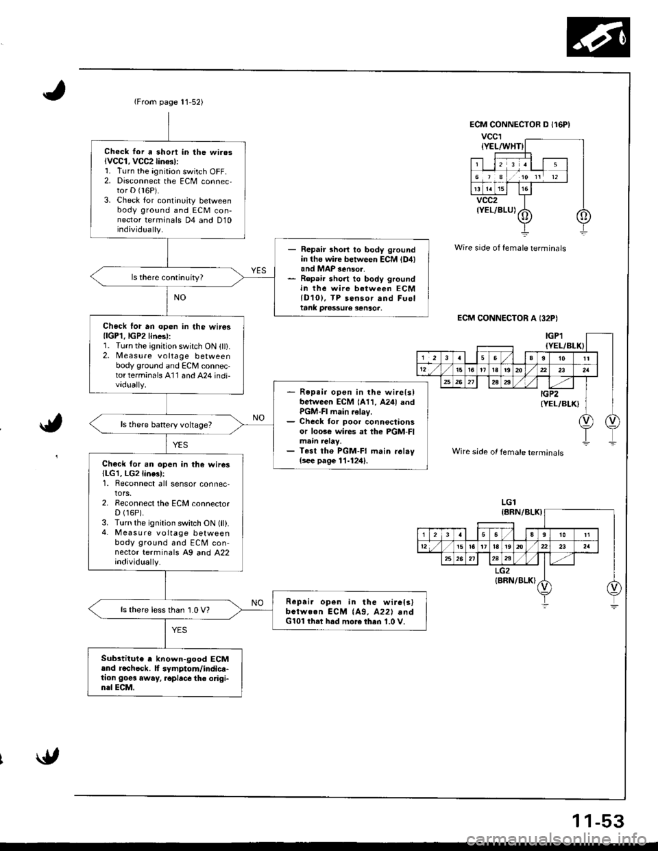
{From page 11 52)
Chock lor a shon in lhe wi.asiVCC1. VCC2lin$l:1. Turn the ignition switch OFF-2. Disconnect the ECM connec,tor D (16P).
3. Check lor continuity betweenbody ground and ECM con-nector terminals D4 and D10individually.
- Repair short to body groundin tho wire between ECM {D4land MAP 3enso..- Rep.ir short to body groundin the wire between ECMlD10l, TP sensor and Fueltank pa6ssure sanso..
Chock lor an op€n in the wire3{lGP1.lGP2lines):1. Turn the ignition switch ON (ll).2, Measure voltage betweenbody ground and ECM connec-torterminals A'11 and A24 indi-vadually.- R6pe;r open in the wire{slbetween ECM 1A11, A24l andPGM-FI main .elay.- Check for poor connectionsor loose wi.es at the PGM-FImain relay.- Test tho PGM-FI main ral.v(see page 11-124).Check for an open in the wires(LG1, LG2line3l:1. Reconnect all sensor connec-tors.2. Reconnect the ECM connectorD (16P).
3. Turn the ignition switch ON (ll).4- M easu re voltage betweenbody ground and ECM connector terminals A9 and A22individually.
Repai. open in the wir€ls)bctween ECM {A9, A22l .ndG101 ihet had more then 1.0 V.
ls there lessthan 1.0 V?
Substitute , known-good ECMand rechock. f symptom/indica-tion goes away, roplac6 the odgi-n3l ECM.
Wire side of female terminals
ECM CONNECTOR A I32P)
a,
Wire side of female terminals
LGl
1 1-53