Map sensor ACURA INTEGRA 1998 Service Owner's Manual
[x] Cancel search | Manufacturer: ACURA, Model Year: 1998, Model line: INTEGRA, Model: ACURA INTEGRA 1998Pages: 1680, PDF Size: 53.14 MB
Page 258 of 1680
J
i
'ilPGM-FI System
Manifold Absolute Pressure (MAPI Sensor
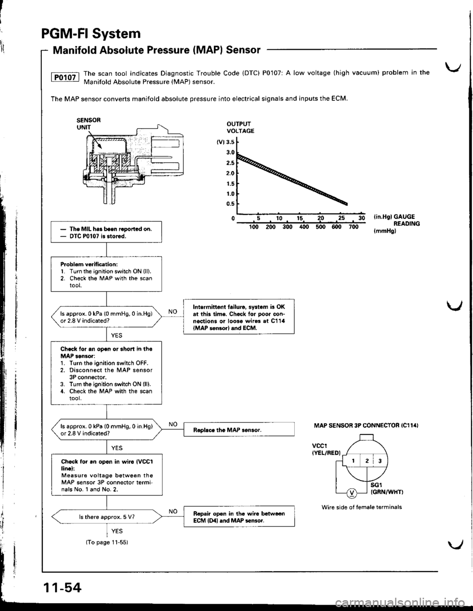
The scan tool indicates Diagnostic Trouble Code (DTC) P0107r A low voltage (high vacuum) problem in the
N4anifold Absolute Pressure (MAP) sensor.
The MAP sensor converts manifold absolute pressure into electrical signals and inputs the ECM.
OUTPUTVOLTAGE
(vt3.5
2.5
2.O
1.5
1.0
0.5
0lin.HglGAUGEREADING(mmHgl
MAP SENSOR 3P CONNECTOR IC114I
vccrIYEL/REDI
i
Ii
{
il
The MIL haa baen raportGd on.DTC P0107 is storcd,
Problem ve.ification:L Turn the ignition switch ON (ll).
2. Check th€ MAP with the scantool.
Intermittent tailulo. systam i! OKat thk lime. Chock tor pooa con-noctions or loosa wir.3 al C114{MAP s€n3orl dnd ECM.
ls approx.0 kPa (0 mmHg.0 in.Hg)or 2.8 V indicated?
Chcck lor an opan or 3hoJt in thoMAP 3on!or:1. Turn the ignition switch OFF.2, Disconn6ct th6 MAP sensor3P conn6ctor.3. Turn lhe ignition switch ON (lll.
4. Ch€ck the MAP with the scantool.
ls approx.0 kPa (0 mmHg,0 in.Hg)or 2.8 V indicated?
Ch6ck for .n op.n in wiro IVCCIlin.l:Measure vollage betwe€n theMAP sensor 3P conn€ctor termi'nals No. l and No.2,
R.pair op.n in thc wile lrotweenECM {Dll and MAP sensoi.ls there approx.5 V?
(To page 11-55)
Wire side of female terminals
Page 259 of 1680
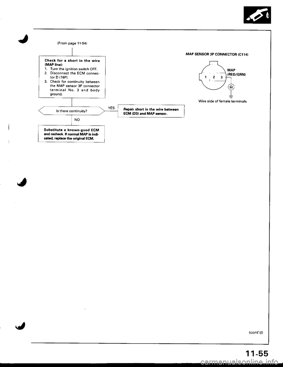
(From page t 1-54)
Check for a 3hort in th€ wiae(MAP linel:1. Turn the ignition switch OFF.2. Disconnect the ECM connector D {16P}.3. Check for continuity betweenthe MAP sensor 3P connectorterminal No. 3 and bodygrouno,
Repeir short in th. wirg b€{woenECM lD3l and MAP s6n3or.
Substitute a known-good ECMand rochack. lf no.mal MAP b indi-catod, r€place the original ECM,
MAP SENSOR 3P CONNECTOR {C114)
MAP(RED/GRN)
Wire side of fomalelerminals
1 1-55
Page 260 of 1680
PGM-FI System
Manifold Absolute Pressure (MAPI Sensor (cont'dl
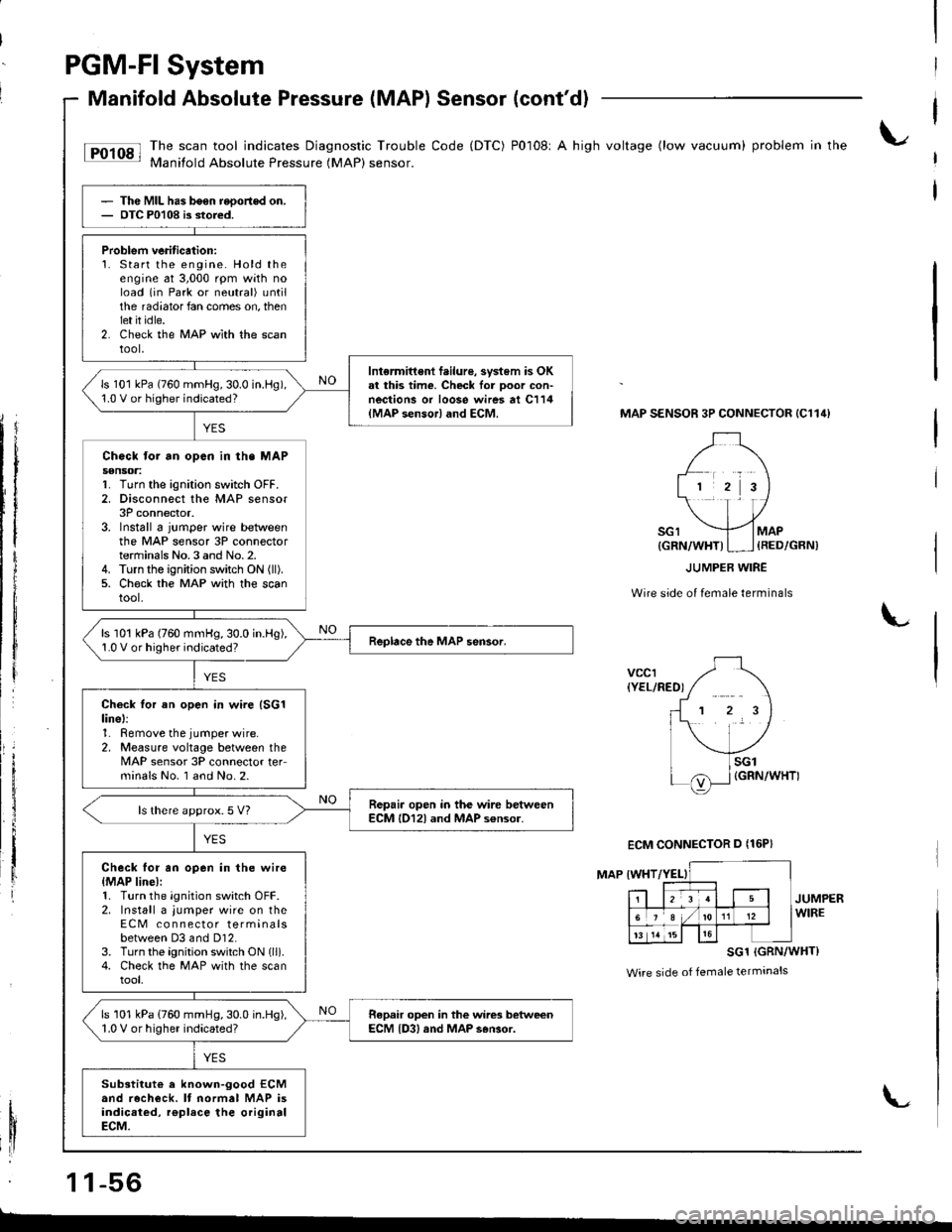
tF'r'sl li:"J:ilfi::il***:ilHi""k:"
code (Drc) P0108' A hish vo*ase (row vacuum) probrem in the
Thc MIL has b6en reoortod on.OTC P0108 is stored.
Problem veritication:1. Start the engine. Hold theengine at 3,000 rpm with noload (in Park or neutral) untilthe radiator fan comes on, thenlet it idle.2. Check the MAP wlth the scantool,
Intermittent f.ilure, svstem is OKal this time. Check lor Door con-nections or loose wires at C114{MAP sensor} and ECM.
ls 101 kPa (760 mmHg,30.0 in.l-lg),1.0 V or higher indicated?
Chock tor an opcn in th. MAPs€nsoa:1. Turn the ignition switch OFF.2. Disconnect the MAP sensor3P connector.3. Install 6 jumper wire betweenthe MAP sensor 3P connectorterminals No.3 and No.2.4. Turn the ignition switch ON (ll).
5. Ch€ck the MAP with the scantool.
ls 101 kPa (760 mmHg,30.0 in.Hg),1.0 V or higher indicated?
Check tor an open in wire (SG1
linel:1. Remove the jumper wire.2, Measure voltage between theMAP sensor 3P connector teFminals No. I and No.2.
Repair open in the wire betweenECM l012l and MAP s€nsor.ls there approx.5 V?
Check for an open in the wire{MAP line):1. Turn the ignition switch OFF.2. Install a jumper wire on theECM co n nector terminalsbetween D3 and Dl2.3. Turn the ignition switch ON lll).4. Check the MAP with the scantool,
ls 101 kPa (760 mmHg,30.0 in.Hg),1.0 V or higher indicated?Repair open in the wires betweenECM {D3, and MAP s6Gor.
Substitut€ a known-good ECMand recheck. It normal MAP isindicaied, rgplace the originalECM.
MAP SENSOR 3P CONNECTOR {C114}
Wire side of female terminals
L
vccr{YEL/RED)
MAP IWHT
JUMPERWIRE
SG1 (GRN/WHT}
Wire side of female terminals
1 1-56
{GRN/WHT)I ] {RED/GRN)
ECM CONNECTOR D {16P}
L
Page 280 of 1680
PGM-Fl System
Fuel Supply System
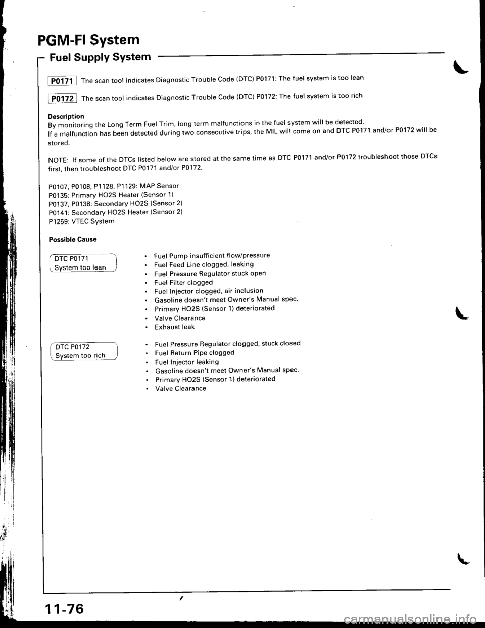
lF0{7il Thescantool indicates Diagnostic Trouble Code (DTC) P0171:Theluel system rstoo lean
[F0i72l Th" ""un tool indicates Diagnosric Trouble code (DTc) p0,172: The fuet system is too rich
Description
By monitoring the Long Term Fuel Trim, long term malfunctions in the luel system will be detected
lf a malfunction has been detected during two consecutive trips, the MIL will come on and DTC P0171 and/or P0172 will be
stored.
NOTE: lf some ol the DTCS lasted below are stored at the same time as DTC PolTl and/or P0172 troubleshoot those DTCS
first, then troubleshoot DTC P0171 andlot P0172
PO107, P0108, P1128. P1129: MAP Sensor
P0135: Primary HO2S Heater (Sensor 1)
P0137, P0138: Secondarv HO2S (Sensor 2)
P0141: Secondary HO2S Heater (Sensor 2)
P1259: VTEC Svstem
Possible Cause
DTC P0171
too lean
Drc P0172
Svstem too rich
. Fuel Pump insufficient flowpressure
. Fuel Feed Line clogged, leaking
. Fuel Pressure Regulator stuck open
. Fuel Filter clogged. Fuel Iniector clogged, air inclusion
. Gasoline doesn't meet Owner's Manual spec.
. Primary HO2S (Sensor 1)deteriorated
. Valve Clearance. Exhaust leak
. Fuel Pressure Regulator clogged, stuck closed
. Fuel Return Pipe clogged
. Fuel Iniector leaking
. Gasoline doesn't meet Owner's Manual spec
' Primary Ho2s (Sensor 1) deteriorated
. Valve Clearance
Page 283 of 1680
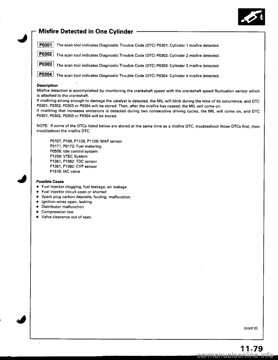
Misfire Detected in One Cylinder
I P0301 The scan tool indicates Diagnostic Trouble Code (DTC) PO3O1:Cylinder 1 misfire detected.
[F03021 1;," """n tool indicares Diagnostic Troubte Code (DTC) pO3O2: Cylinder2 misfire detected.
P0303 | ths sssn tool indicates Diagnostic Trouble Code (DTC) PO3O3: Cylinder3 misfire detected.
i P0304 | tne scan tool indicates Diagnostic Trouble code {DTC} PO3O4: Cylinder 4 misfire detected.
Doscription
Misfire detection is accomplished by monitoring the crsnkshaft speed with the crankshaft speed fluctuation sensor whichis attached to the crankshaft.
lf misfiring strong enough to damage the catalyst is detected, the MIL will blink during the time of its occurrence, and DTCP0301, P0302, P0303 or P0304 will be stored. Then, after the m;sfire has ceased, the MIL witt come on.lf misfiring that increases emissions is detected during two consecutive driving cycles, the MIL will come on, and DTCP0301, P0302, P0303 or P0304 will be stored.
NOTE: lf some of the DTCS listed below are stored at the same time as a misfire DTC, troubleshoot those DTCS first, thentroubleshoot the misfi.e DTC.
P0107, P108, P1128,P'1129: MAP sensor
PO171, PO172t Fuel metering
P0505; ldle control system
P1259: WEC System
P1361, P1362: TDC sensor
P138'1, P1382: CYP sensor
P1519: IAC valve
Possibls Caus6
. Fuel injector clogging, fuel leakage, air leakage
. Fuel injector circuit open or shoned. Spark plug carbon deposits, fouling, malfunction. lgnition wires open, leaking
. Distributor malfunction
. Compression low
a Valve clearance out of spec.
(cont'd)
11-79
Page 1072 of 1680

Connector ldentification and Wire Harness Routing
Connectot or
Terminal
Numbel of
CavitiesLocationConnects toNotes
c'to 1
c102
c103
c'1 04
c105
c106
c 107
c108
c108
c109
c110
c112
c113
c'r 14
c115
c116
c117
c118
ct'l9
c119
c120
c121
c122
c124
c't 26
c127
c128
c129
c130
c111
4
10
14
6
I
1
2
2
10
2
3
2
J
4
3
3
2
2
I
3
2
2
2
2
2
I
2
14
Right side of engine compartment
Right side of engine compartment
Right side ot engine compartment
Right side of engine compartment
Right side oI engine compartment
Right side of engine
Right side of engine
Transmission
Transmission
Middle ot engine
Middle ot engine
Right side of engine
Right side of engine compartment
Middle rear of engine compartment
N4iddle of engine
N4iddle ol engine
Middle oI engine
Nliddle ot engine
Middle of engine
Lelt side of engine
Left side of engine
Middle of engine
Middle oI engine
Middle of engine
Middle of engine
Middle ot engine
Left side of engine compartment
Lelt side ot engine compartment
Left side of engine compartment
Transmission
Transmission
Transmission
Main wire harness (C221)
Main wire harness (C222)
Main wire harness 1C223)
lvlain wire harness (C220)
Starter solenoid
Engine coolant temperature (ECT)
sensor
Engine coolant temperature (ECT)
gauge sending unit
Back-up light switch
Lock-up control solenoid valve A and B
Distributor
Crankshatt speed fluctuation (CKF)
sensor
Engine coolant temperature (ECT)
switch
Vehicle speed sensor (VSS)
Primary HO2S
MAP sensor
Throttle position (TP) sensor
ldle air control (lAC) valve
EVAP purge control solenoid valve
Engine oil pressure switch
Alternator
Alternator
lntake air temperature (lAT) sensor
No. 1 fuel injector
No. 2 fuel injector
No. 3 fuel injector
No. 4 fu€l injector
Junction connector
Engine compartment wire harness
(c304)
Engine compartment wire harness
(c30s)
Shift control solenoid valve A and B
Countershaft speed sensor
lvlainshaft speed sensor
M/T
NT
USA
Canada
Afi
Afi
T101
T102
Left side oI engine
Right side of engine compartment
Alternator
Under hood fuse/relay box
G'1 01Right side oI engineEngine ground. via engine wire
harness
Engine Wire Harness (B188l enginel
23-16
Page 1074 of 1680

Connector ldentification and Wire Harness Routing
Engine Wire Harness (B18Cl enginel
Connectol ol
Terminal
Number of
CavitiesLocationConnects toNotes
c 101
c102
c103
c104
c105
c106
c101
c108
cr09
c110
c'r 11
cl12
c1't3
c114
c115
c116
cl17
c118
c119
c119
c120
cI2'l
cl24
c126
c127
cl31
c132
c133
c134
10
14
3
1
2
1
2
10
2
'I
3
2
2
2
I
1
2
2
?
3
2
14
Right side of engine compartment
Right side of engine compartment
Right side of engine compartment
Right side ol engine compartment
Right side of engine compartment
Righr side oI engine
Right side of engine
Transmission
Middle of engine
Middle of engine
Right side of engine
Right side of engine compartment
Middle rear of engine compartment
Middle of engine
Middle of engine
Middle of engine
Middle of engine
i/iddle of engine
Left side ot engine
Lelt side ot engine
Middle ot engine
Middle of engine
Middle of engine
Middle of engine
Middle of engine
Left side of engine companment
Left side of engine compartment
Lelt side of engine compartment
Right side of engine
Right side of engine
Middle of engine
Middle of engine
lvlain wire harness (C221 )
Main wire harness {C222)
Main wire harness (C223)
Main wire harness (C220)
Starter solenoid
Engine coolant temperature (ECT)
sensor
Engine coolant temperature (ECT)
gauge sending unit
Back-up light switch
Distributor
Crankshalt speed fluctuation (CKFI
sensor
Engine coolant temperature {ECT)
switch
Vehicle speed sensor (VSS)
Primary HO2S
MAP sensor
Throttle position {TP) sensor
ldle air control (lAC) valve
EVAP purge control solenoid valve
Engine oil pressure switch
Alternator
Alternator
Intake air temperature llAT) sensor
No. 1 fuel injector
No. 2 fuel injector
No. 3 tuel injector
No. 4 tuel injector
Junctron connector
Engine compartment wire harness(c304)
Engine companment wire harness(c30s)
VTEC solenoid valve
VTEC oil pressure switch
Knock sensor (KS)
Intake air bypass {lAB) control sole-
noid valve
USA
Canada
T101
r 102
Left side ot engine
Right side of engine compartment
Alternator
Under-hood fuse/relay box
G 101Right side of engineEngine ground, via engine wire
naaness
23-18
Page 1437 of 1680

---1 ENGINE, i -l I CONTBOL, ,.^^ ':rr^^','EIAB ; i MODULE tsnition r\,tAP : [?uor : I itei-ttti o-utprrt Ref€renc€ sensor Sensor ; solenoid , I puoro zz
I Ground Ground Ground signal voltage input ground ' valve control ' Ij ,.^";, ',&, ,PGIr {rcM' {vBc1' iMAPD (PB' ,B?;) | u**tuo., lJ_ _ - - _.
1-,-f =--:--------;f-s1oT---l-r[-;;"f --l
I u",n'* |
'l
;l-;;l -;[-;J"." i;["."
! i#qill- | I | ,L-_+
::t,*,"
i
",f
,*,,.
-!-i-.LH
| ;L:,[ -{.* i."l
**I "..1 | lr**
ll
i I*.1
ltl+]il
.tr*,, .ir*., ,,ir*,.
*"R?!K"":"(h'J'5
i 'fB;2,,
-l
.f ,*,.
;i{,_
""'''''#rr";{
i""11",..
I t'i{t: I
r;=t=;i
im'WS*r'
lj:tl Lds:i il***
[ |
t!'J.$""'Jo'
il
*l -.1
i !3P*q;r"r
L )
'""!-it
'*\,FF$!?'trr"1
,l*i: PHora2a
| :
":::"
.
(cont'd)
23-3
Page 1445 of 1680
 (r,Gzl rpclr rtcM) (vccl) {MAP eB) (sG1)I B2o Blo 82 413 c19 c17 c7
I
I
\
MANIFOLD ABSOLUTEPRE")
lgnition MAP
d',rtput Rsfetenag sensor Sensor
I Ground Ground Groud signal vollago input ground
: rLGl) (r,Gzl rpclr rtcM) (vccl) {MAP eB) (sG1)I B2o Blo 82 413 c19 c17 c7
I
I
\
MANIFOLD ABSOLUTEPRESSURE (MAP)SENSOR
POWERTRAINor ENGINECONTROLMODULE(PCM o. ECM)
c102c301
c127i[::
YEUGRN
See GroundDistribution,paos 14.
10
See GroundDistribution,pages !4and 1+1.
-i
"L
:p
I lg:Ll- I
I ii5ilr I
lGNtTtot{coxTnolMODULf
0cM)L-----J
DISTRIBUTORASSEMBLY
(cont'd)
24-3
Page 1597 of 1680

Connector ldentification and Wire Harness Routing (cont,d)
Connector
or
Terminal
Number ot
Cavities/
Color
LocationConnects toNotes
Engine Wire Harness (RS, LS, GS)
c101
c102
c103
c104
c105
c106
c 107
c108
c108
c'1 09
c110
c111
cl12
c113
c'114
c115
c116
c117
c118
c119
c1 19
c120
c121
c122
c123
c124
cl25
cl26
c127
Ql28
c128
c129
c 129
c130
c'l30
c131
4.GRY
1O.GRY
14-GRY
6-GRY
1.BLK
2-GRY
,1-BLK
2-GRY
2.GRY
1O-GRY
2-GRY
2-GRY
3-GRY
4-GRY
3-GRY
3-GRY
2-GRY
2.BLK
.1-BLK
4-GRN
3-GRN
2-GRY
2.BLK
2-BLK
2-BLK
2.BLK
8-GRY
2-GRY
14-GRY
3-GRY
2.GRY
2.GRY
2-BLK
3-GRY
2-BLK
2-BLK
Right side of engine compartment
Right side of engine compartment
Right side ot engine compartment
Right side of engine compartment
Right end of engine
Right end of engine
Right end of engine
Transmission
Transmission
lvliddle ol engine
Lett rear underside of engine
Right side ol engine
Rear of engine compartment
Middle rear ol engine compartment
Middle ol engine
Middle of engine
Middle ol engine
l\4iddle of engine
Middle of engine
Left end ot engine
Lett end of engine
Middle of engine
N,liddle ol engine
Middle of engine
Middle of engine
Middle of engine
Left rear corner of engine compt.
Lelt rear corner of engine compt.
Left rear corner of engine compt.
Transmission
Transmission
Transmission
Transmission
Transmission
Transmission
Transmission
Main wire harness
Main wire harness
Main wire harness
Main wire harness
Starter solenoid
Engine coolant temperature (ECT)sensor
Engine coolant temperaturegauge sending unit
Back-up light switch
Lock-up control solenoid valve Aand B
Distributor
Crankshaft speed fluctuation (CKF)sensor
Radiator fan switch
Vehicle speed sensor (VSS)
Primary heated oxvoen sensor(H02s)
MAP sensor
Throttle position (TP) sensor
ldle air control (lAC) valve
Evaporative emission (EVAP)purge control solenoid valve
Engine oil pressure switch
Alternator
Alternator
Intake air temperature (lAT) sensor
No. I fuel injector
No. 2 fuel injector
No. 3 tuel injector
No. 4 fuel injector
Junction connector
Engine compartment wire harness
Engine compartment wire harness
Shitt control solenoid valve A and B
Shift control solenoid valve A and B
Countershaft speed sensor
Countershatt speed sensor
lvtainshatt speed sensor
Mainshaft speed sensor
Linear solenoid valve
NT
[/VT
A"/T
USA
Canada
A/T (98199models)
AIT('00 model)
A,/T ('98-'99models)
('00 model)
A,/T f98-'99models)
Atf('00 model)
AN('00 model)
T101
T102
Left end of engine
Right rear corner of engine compt.
Alternator
Under-hood fuse/relay box
G'101Right end ot engineEngine ground, via engine wirenarness
o
I
203-2