ACURA INTEGRA 1998 Service User Guide
INTEGRA 1998
ACURA
ACURA
https://www.carmanualsonline.info/img/32/56983/w960_56983-0.png
ACURA INTEGRA 1998 Service User Guide
Page 1204 of 1680
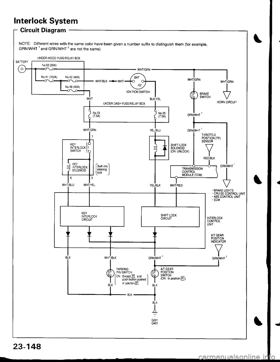
lnterlock System
Circuit Diagram
NOTE: Different wires with the same color have been given a number suflix to distinguish them (for example,cRNA/VHT I and cRNMHT '� are not the same).
WHT/ BLK .-- WHI
cnrruvgr'
+. BRAKE LIGNTS.CSUISE CONTROLUNIT. ABS COIITROL UNIT' ECM
INTEBLOCKCONTROLUNIT
A]'IGEARPOStTIONINOICATOR
v
t,
UNDER-HOOO FUSEi RELAY BOX
N0.41 (100A) N0.42 (404)
YEUBLUcnrivrr '
WHT/BLU
KEYINTERLOCKswtTcH
THBOTTLEPosrT|0N (TP)SENSOR
f7
IRED/BLK
(Cjl :in posiron E t
23-14A
Page 1208 of 1680
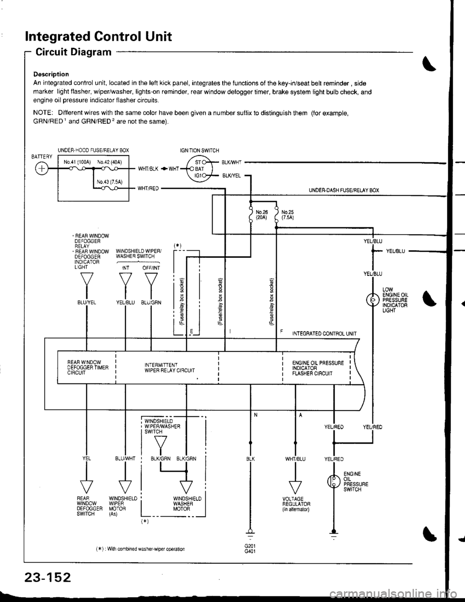
Integrated Control Unit
Circuit Diagram
Description
An integrated control unit, located in lhe left kick panel, integrates the lunctions of the key-in/seat belt r€minder , side
marker light llasher, wiper/washer, lights-on reminder, rear window delogger timer, brake system light bulb check, and
engine oil pressure indicator flasher circuits.
NOTE: Different wires with the same color have been given a nu mber suflix to distinguish them (for example,
GRN/RED I and GRN/RED'� are not the same).
REAR WINDOWDEFOGGERRELAYREAF WINDOWDEFOGGENIND CATORL GHT
f-7
IIBLU/YEL
WHT/ BLK
WHT/ REO
+WHT
WNDSHIELDWIPERiWASHER SWITCH
INT OFF/INT
f7 f7
tltlYEUBLU 8LU/GRN
BLUMHT
J
wtN0sHr€10WIPERMOTOR
UNDER.DASH FUSARETAY BOX
F rmecnlleo counoL ultr
YEUBLU
rYEUBLU
YEUREO YEUREO
tl
IYEURED
LOWENGINEOIIPRESSUREINOICATOBLIGHT
; WINDSHIELD' WIPERMASHERI swlTcH
tf7IVtlYEL
J
FEARwtN00wOEFOGGERSWITCH
WHTIBLU
J
VOTTAGEREGULATOR(ln allernatol)
BLK
G441
ENGINEolLPRESSUREswrTcH
UNDER-NOOO FUSE/RELAY BOX
1.6
:6
t;t-L
i
"'i'- 'i*-
|
I Il
I vi: WINDSHIELO II WASHEB I
L__ "oto: _ __l(*)
n
s
s
,]
23-152
(*) :Wilh combined washer-wiper operalion
Page 1218 of 1680
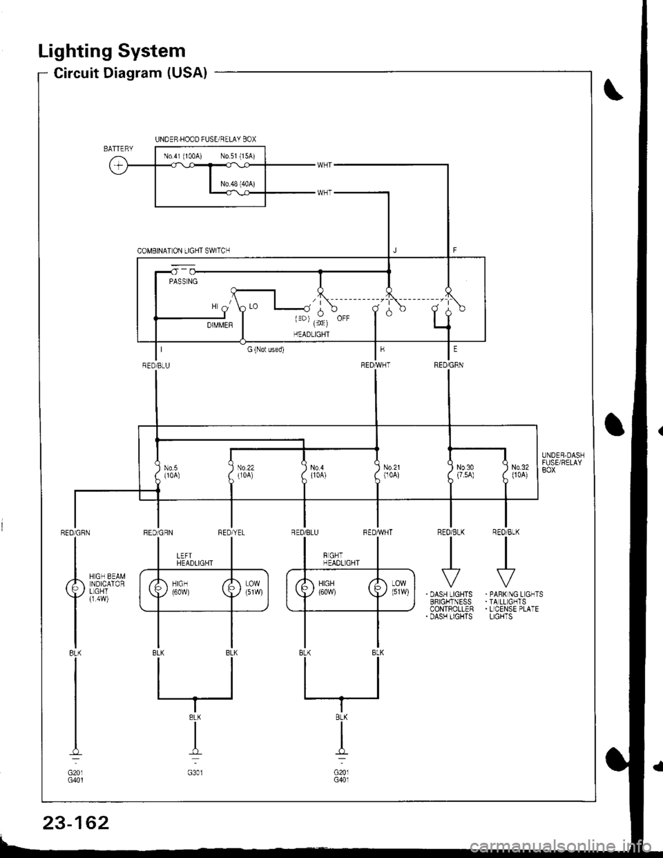
Lighting System
Circuit Diagram (USA)
R€O/BtK
I
REO/BLKIII
I
. OASH LIGHTSBFIGI.ITNESSCONTROLLER. DASH TIGHTS
RED/CRN
I
Ailsurax
Yller,l
IBL(
I
I
I-l
G201G401
. PANK NG L GNTS.TA LL GHTS. LICENSE PLATELIGHTS
UNDER.HOOD FUSE/RELAY BOX
RED]BtU
N0.21(104)No.5{10A)
III No22 I No4( lroA) ( {1oA)
IT
INo30 :(7.5A) (
I
N0.3200A)
8LK
I
G20lG40l
23-162
Page 1219 of 1680
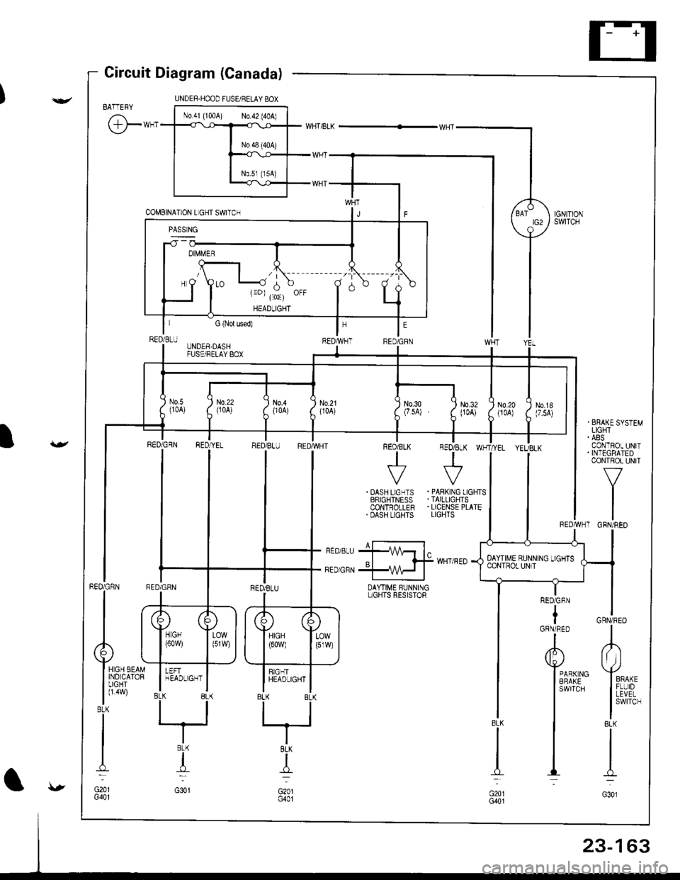
UNDER.HOOD FUSE/RELAY BOX
No 41 {100A) N0.42 (40A)
,/ |\
\--, ({c)
HEADLIGHT
Circuit Diagram (Canada)
BATTEFY
@-**
I I :i,ff'*''"
I CoNTFOL UN|TI . INTEGBATED
l-v^"
tl
tlREDAVHT GRN/RED
GRN/FED
L
lt ))
Yro^,
I iivP,
I
swrrcH
BLK
I
I-l
G301
RED/GFN
tGRN/RED
A
Y*r*ro
I
3Ai{5"
I
I
I
DAYTIME BUNNINGL]GHIS RESISTOR
UNDER.DASHFUSE/FELAY BOX
) No.21
i
uoo') N0.20{JOA))'
) N0.18(7.5A))'
II
lrrt,
llrffi ltlrr
INo.3o Q
(7.sA) . (
I
N0.32(104)
RED GqN RED YE- RED BL- REDTVHT FED/BLK REO/8LK WHT/YEL YEUBLK
| + +ll
I
i*n[i+'i .ffi$liilTl
II ri---J- i---F BEDE-U +1 4- l^ |
l,,oo,* *qff
.'""0
{36['45,1'il]''
23-163
Page 1234 of 1680
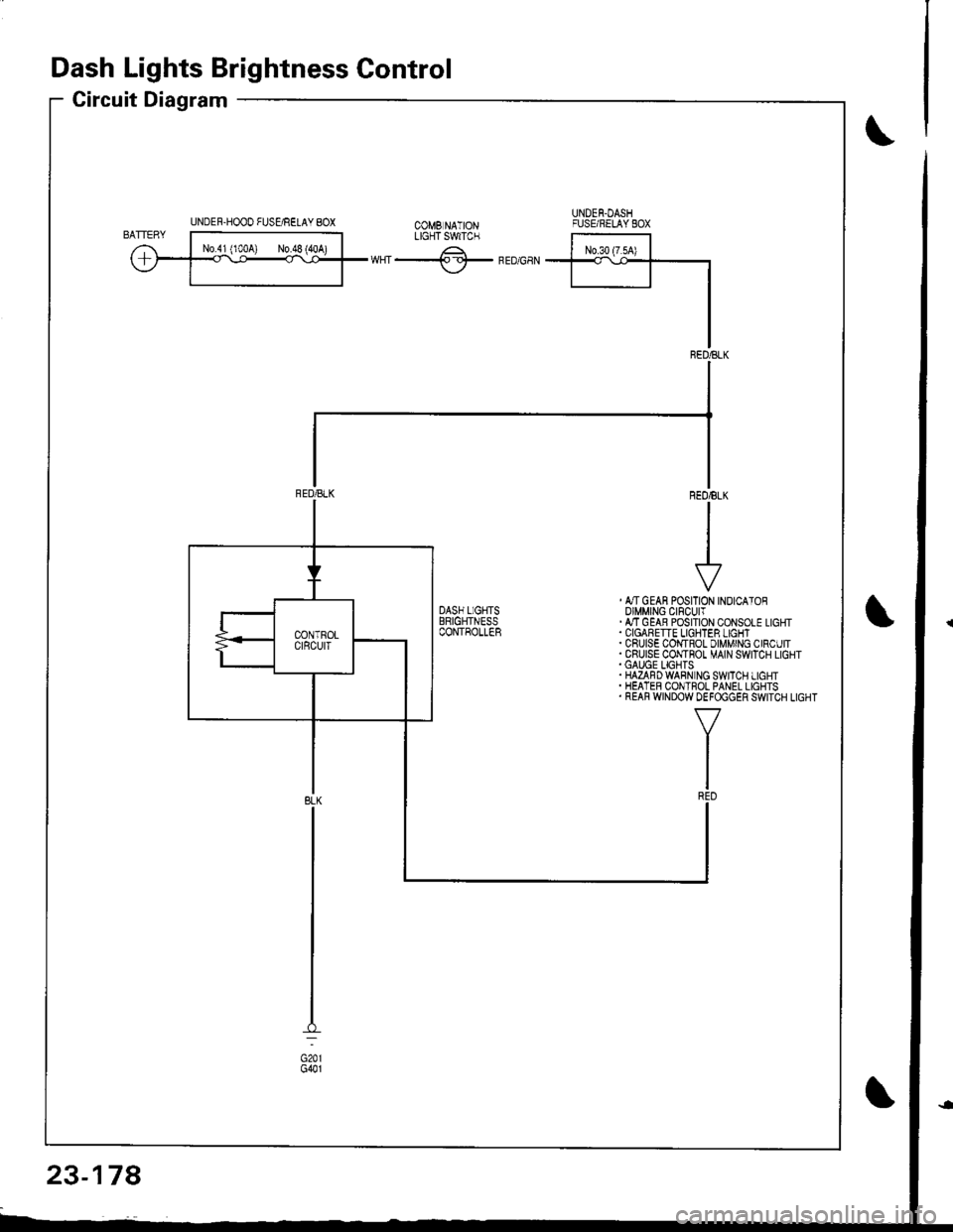
Dash Lights Brightness Control
Circuit Diagram
UNDER-HOOO FUSgRELAY 8OXUNDEN.DASHFUSE/RELAYEOXtX"f -.------^-;^*;;ilLrcrTswrc.
ffiwHT-lf-FEDGaN
, &TGEAN POSITION INOICATOROIMMING CIFCUIT.ATTGEAB POSITION CONSOLE LIGHT
. CRUISE COI,{TROL DIMMING CIRCUIT.CRUISE CONTHOT MAIN SWITCH LIGHT.GAUGE LIGHTS.HAZAFDWABN NG SWITCH LIGHT. HEATER CONTROL PANEL LIGHTS. REAR WINDOW DEFOGGER SWITCH LIGHT
23-178
Page 1243 of 1680
Back-up Lights
Circuit Diagram
IGNITIONswlTcHUNOER.HOOD FUSEi RELAY BOX
EACK.UPLIGHTswtTcH/ / on lhe \r I ransnBgon I
GRN/BLK
IIJ
TRAILERL]GHT NGCONNECTOR
GRN/BLK
IzA arcx.upI P ' LIGHTS
f
r:zce'21
IBLK
II
I
G503
YEL
I
SnoriARr*r.r r*i(3;f;iil're' )V(oN h posirion [E )
l"
IGRN/BLK
23-147
)
I
Page 1245 of 1680
)
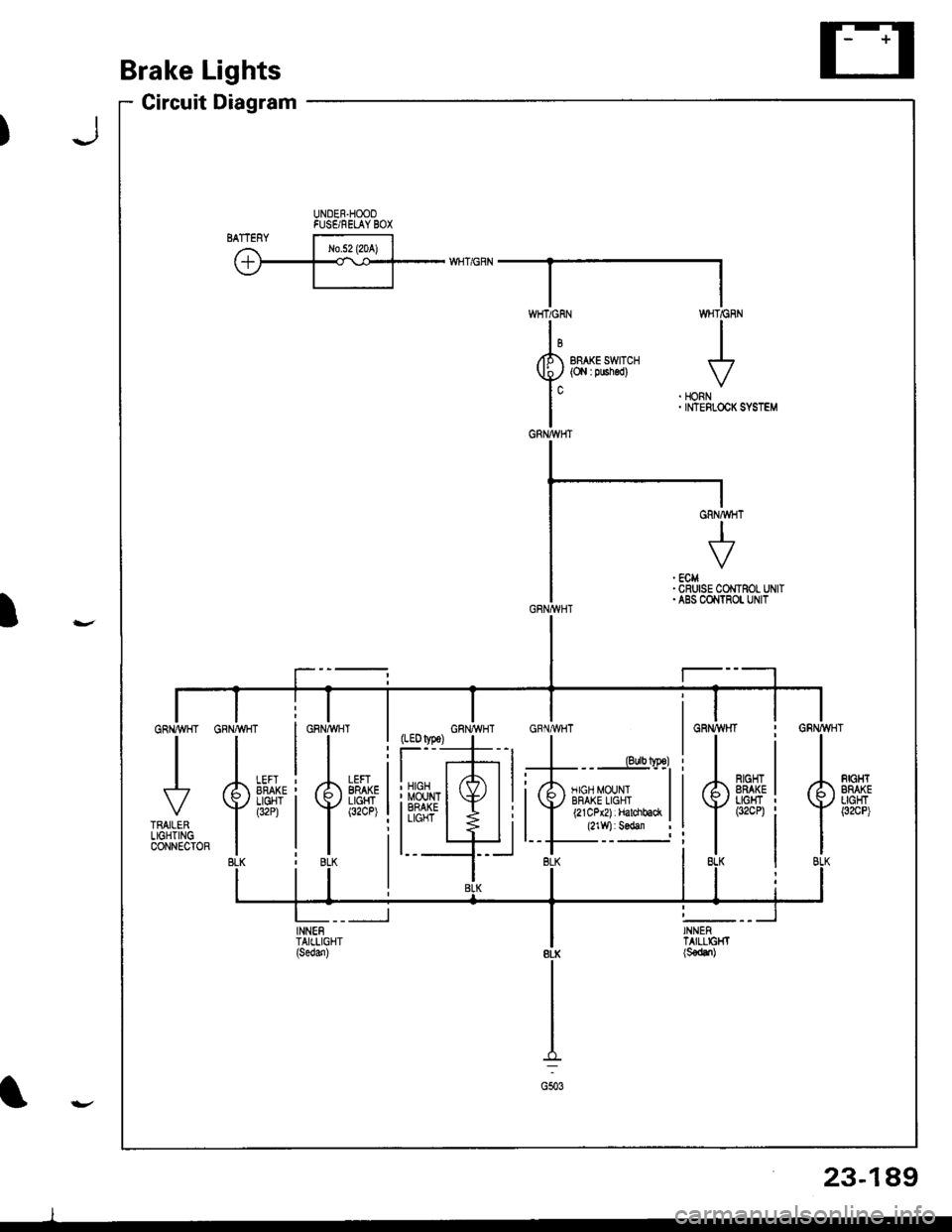
Brake Lights
Circuit Diagram
UNDER.HOOOFUSE/RELAY BOX'ry
BRAKE SWITCH(O,l I pushed)
WHT/GF
I
HONNINTEFLOCK
,#�,.^{.
LEFIBRAKELIGHT(32CP)il
:li
l_t
INNENTAIILIGHT
WHTiGRN
GRNA{HT
J
GRNMHT
23-189
l
I
Page 1249 of 1680
Circuit Diagram
UNDEB HOOD FUSUBELAY 8OX
N0.41 (100A) No.5l (l5A)
UNDER DASHFUSE/FELAY BOXCOMEINATIONLIGHT SWITCH
wHT ---{. rcr- RED/GRNV rclrrtor swror
WHT/BLK +WNTBLK/YEL
WHT/GRN
I GFNBLU GRIVBLU
-]JJ
IVVGRNIELU TRATLERI L|GHTINGI CONNECTOR
TRUN SIGNALswrTcHF (Not used)
GBN/ORN
GRNioRN-
GRNALU GRN/BLU
RED
tltl
rl
I
t
OASH LIGHTSBFIGHTNESSCONTROLLEH
*f --.f ,-+r*n"+
RN/YE
t
TBLK
GRN,YEL
tttol
I RE,
lo'8LK
8LK
I
G201G401
GFN/BLU
)
23-193
Page 1254 of 1680
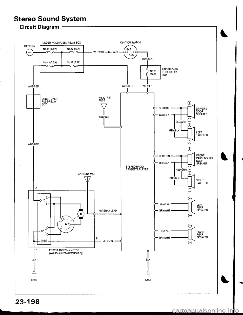
Stereo Sound System
Circuit Diagram
WHT/RED
tWHTi RED
UNDER.HOOD FUSE / RELAY BOX
UNDER.DASHFUSE/RELAYBOX
N0.30 (7.5A)FUSE
f7
IRED/BLK
UNDER,DASHFUSE/RELAYBOX
FRONTPASSENGER'SoooRSPEAKER
ANTENNA MAST
LEFTREABSPEAKER
RIGHTREARSPEAKEB
rna-ll
-ttl
;\\:/
o=4-ll
-{tl
x!\:/
ANTENNA LEAD
BLU,YEL
GRY/rrVHT
REO/YEL
ERNMHT
POWER ANTENNA MOTOR{wilh lhe antenna reraded lully)
BLK
I
G551
8LK
I
G503
No 4l (100A) No 42 (40A)
rc\RED/GRN VSTEBEO RADIOiCASSETTE PLAYER
23-198
Page 1262 of 1680
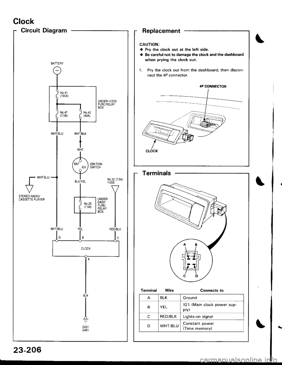
Clock
CircuitDiagram
CAUTION:
a Prv the clock out at the left side.
a Be careful not to damage the clock and the dashboard
when prying the clock out.
1. Pry the clock out from the dashboard. then discon-
nect the 4P connector.
4P CONNECTOR
CLOCK
BATTERY
UNDER,HOODFUSE/RELAYBOX
WI-]T/BLK
I
A/ BAT I 1GN TION
Y*"t No3o(7.sA)-|" -v
F'nrrn l
I
WHT/BLU
l- wHT 8LU
al-
STEREO BADIOiCASSETTE PLAYEF
BLK
G201G401
BLKGround
BYELrG1
pry,
(Main clock power sup-
cRE D/BLKLights-on signal
DWHT/BLUConstant power
(Time memory)
Terminals
23-206

![ACURA INTEGRA 1998 Service User Guide Back-up Lights
Circuit Diagram
IGNITIONswlTcHUNOER.HOOD FUSEi RELAY BOX
EACK.UPLIGHTswtTcH/ / on lhe \r I ransnBgon I
GRN/BLK
IIJ
TRAILERL]GHT NGCONNECTOR
GRN/BLK
IzA arcx.upI P LIGHTS
f
r:zce21
I ACURA INTEGRA 1998 Service User Guide Back-up Lights
Circuit Diagram
IGNITIONswlTcHUNOER.HOOD FUSEi RELAY BOX
EACK.UPLIGHTswtTcH/ / on lhe \r I ransnBgon I
GRN/BLK
IIJ
TRAILERL]GHT NGCONNECTOR
GRN/BLK
IzA arcx.upI P LIGHTS
f
r:zce21
I](/img/32/56983/w960_56983-1242.png)
![ACURA INTEGRA 1998 Service User Guide Circuit Diagram
UNDEB HOOD FUSUBELAY 8OX
N0.41 (100A) No.5l (l5A)
UNDER DASHFUSE/FELAY BOXCOMEINATIONLIGHT SWITCH
wHT ---{. rcr- RED/GRNV rclrrtor swror
WHT/BLK +WNTBLK/YEL
WHT/GRN
I GFNBLU GRIVBLU
-] ACURA INTEGRA 1998 Service User Guide Circuit Diagram
UNDEB HOOD FUSUBELAY 8OX
N0.41 (100A) No.5l (l5A)
UNDER DASHFUSE/FELAY BOXCOMEINATIONLIGHT SWITCH
wHT ---{. rcr- RED/GRNV rclrrtor swror
WHT/BLK +WNTBLK/YEL
WHT/GRN
I GFNBLU GRIVBLU
-]](/img/32/56983/w960_56983-1248.png)
