tdc ACURA INTEGRA 1998 Service User Guide
[x] Cancel search | Manufacturer: ACURA, Model Year: 1998, Model line: INTEGRA, Model: ACURA INTEGRA 1998Pages: 1680, PDF Size: 53.14 MB
Page 244 of 1680
I
t
h,,l,!
il
Troubleshooting
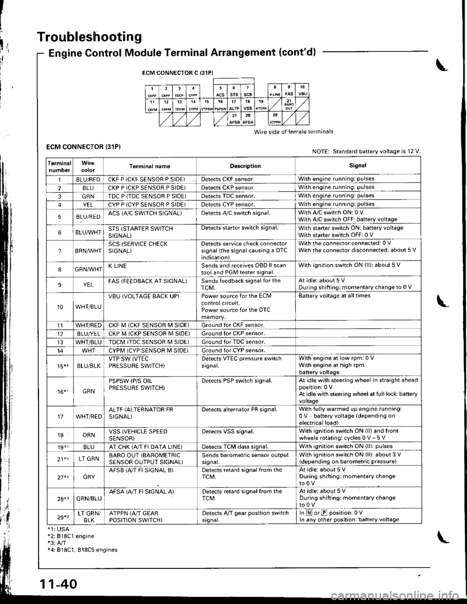
ECM CONNECTOR {31P)
Engine Control Module Terminal Arrangement (cont'd)
ECM CONNECTOR C {31P)
235srsscs1112t31515t71A19
2A
Wire side of lemale terminals
NOTE: Standard battery voltage is 12 V.
TerminalnumbercolorTerminal namoD6scriptionSignal
1BLU/REDCKF P (CKF SENSOR P SIDE)Detects CKF sensor.With engine running: pulses
28LUCKP P (CKP SENSOR P SIDE)Detects CKP sensor.With engine running: pulses
3GRNTDC P {TDC SENSOR P SIDE)Detects TDC sensor,With engine running: pulses
YELCYP P (CYP SENSOR P SIDE)Detects CYP sensor,With engine running: pulses
5BLU/REDACS (AJC SWITCH SIGNAL)Detects A,/C switch signal.With A,/C switch ON: 0 VWith A,/C switch OFF: battery voltage
6BLUA/VHTSTS (STARTEB SWITCHSIGNAL)
Detects starter switch signal.With staner switch ON: battery voltageWith starter switch OFF: 0 V
7BRN,AiVHTSCS (SERVICE CHECKSIGNAL)Detects service check connectorsignal (the signalcausing a DTC;ndication).
With the co n nector con nected: 0 VWath the connector disconnected: about 5 V
8GRNAVHTK LINESends and receives OBD ll scantool and PGM tester signal.With ignition switch ON (ll): about 5 V
9YELFAS lFEEDBACK AT SIGNAL)Sends feedback signal for theTCM,At idle: about 5 VDuring shifting: momenlary change to 0 V
10WHT/BLU
VBU (VOLTAGE BACK UP)Power source for the ECMcontrolcircuit,Power source for the DTC
Battery voltage at all times
t1WHT/REDCKF M (CKF SENSOR I\4 SIDE)Ground for CKF sensor.
12BLUI/E LCKP M (CKP SENSOR M SIDE)Ground for CKP sensor.
WHT/BLUTDCM (TDC SENSOR M SIDE)Ground tor TDC sensor.
14CYPM (CYP SENSOR M SIDE)Ground for CYP sensor.
15*.BLU/BLKVTP SW (VTEC
PRESSUFE SWITCH)Detects VTEC pressure switchsr9nal.
With engine at low rpm:0 VWith engine at high rpmlbattery voltaqe
161,GRN
PSPSW (P/S OILPRESSURE SWITCH)Derecls PSP switch signal.At idle with steering wheel in straight aheadpositioni 0 VAt idle with steering wheelat full lock: batteryvoltage
17WHT/REDALTF (ALTERNATOR FRSIGNAL)Detects alternator FR signal.With fully warmed up engine running:0 V battery voltage (depending onelectrical load)
18ORNVSS (VEHICLE SPEEDSENSORiDetects VSS signal.With ignition switch ON (ll) and lrontwheels rotating: cycles 0 V- 5 V
19*3BLUAT CHK (A/T FI DATA LINE)Detects TCM data signal.With ignition switch ON (ll)i pulses
21*LT GRNBARO OUT (SAROMETRIC
SENSOR OUTPUT S!GNAL)Sends barometric sensor outputsrgnal,With ignition switch ON (ll): about 3 V(depending on barometric pressure)
27 x3GRYAFSB (A"/T FI SIGNAL B)Detects retard signal from theTCM,At idle: about 5 VDuring shifting: momentary changeto0V
28+1GRN/8LUA+SA (A/T FI SIGNAL A)Detects retard signal from theTCM.At idle: about 5 VDuring shifting: momentarV changeto0V
29+3LT GRN/BLKATPPN (A/T GEARPOSITION SWITCH)Detects A,/T gear position switchsrgnal-In E orE positionr 0VIn anv other position: battery voltage
*1: USA*2:818C1 engine*3: A/T*4: 818C1, 818C5 engines
Page 249 of 1680
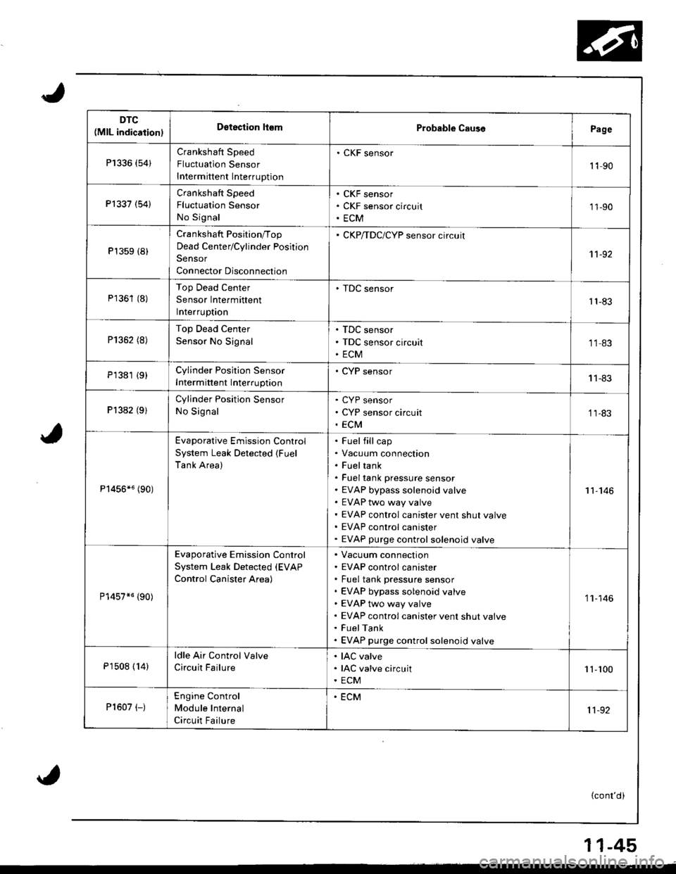
DTC(MlL indication)Dstection ll€mProbable CausePage
P1336 (54)Crankshaft Speed
Fluctuation Sensor
Intermittent lnterruption
. CKF sensor
1190
Pl337 (54)Crankshaft Speed
Fluctualion Sensor
No Signal
CKF sensor
CKF sensor circuit
ECM
'11-90
P't359 (8)
Crankshaft Position/Top
Dead Center/Cylinder Position
Sensor
Connector Disconnection
CKP/TDC/CYP sensor circuit
1't -92
P1361 (8)Top Dead Center
Sensor Intermittent
Interruptaon
. TDC sensor't1-83
P1352 (8)Top Dead Center
Sensor No Signal
TDC sensor
TDC sensor circuit
ECM
1183
P1381 {9}Cylinder Position Sensor
Intermittent Interruption
. CYP sensor11-83
Pl382 (9)Cylinder Position Sensor
No Signal
CYP sensor
CYP sensor circuit
ECM
11-83
P1456*6 (90)
Evaporative Emission Control
System Leak Detected (Fuel
Tank Area)
Fuel fill cap
Vacuum connection
Fueltank
Fuel tank pressure sensor
EVAP bypass solenoid valve
EVAP two way valve
EVAP control canister vent shut valve
EVAP control canister
EVAP purge control solenoid valve
11-146
P14s7*5 {90)
Evaporative Emission Control
System Leak Detected (EVAP
Control Canister Area)
Vacuum connection
EVAP control canister
Fuel tank pressure sensor
EVAP bypass solenoid valve
EVAP two way valve
EVAP control canister vent shut valve
FuelTank
EVAP purge control solenoid valve
'1 'l - 146
P1508 ( 14)
ldle Air Control Valve
Circuit Failure
IAC valve
IAC valve circuit
ECM
1 1-100
P1607 (-)Engine Control
Module Internal
Circuit Failure
. ECM
11-92
(cont'd)
11-45
Page 252 of 1680
PGM-FI System
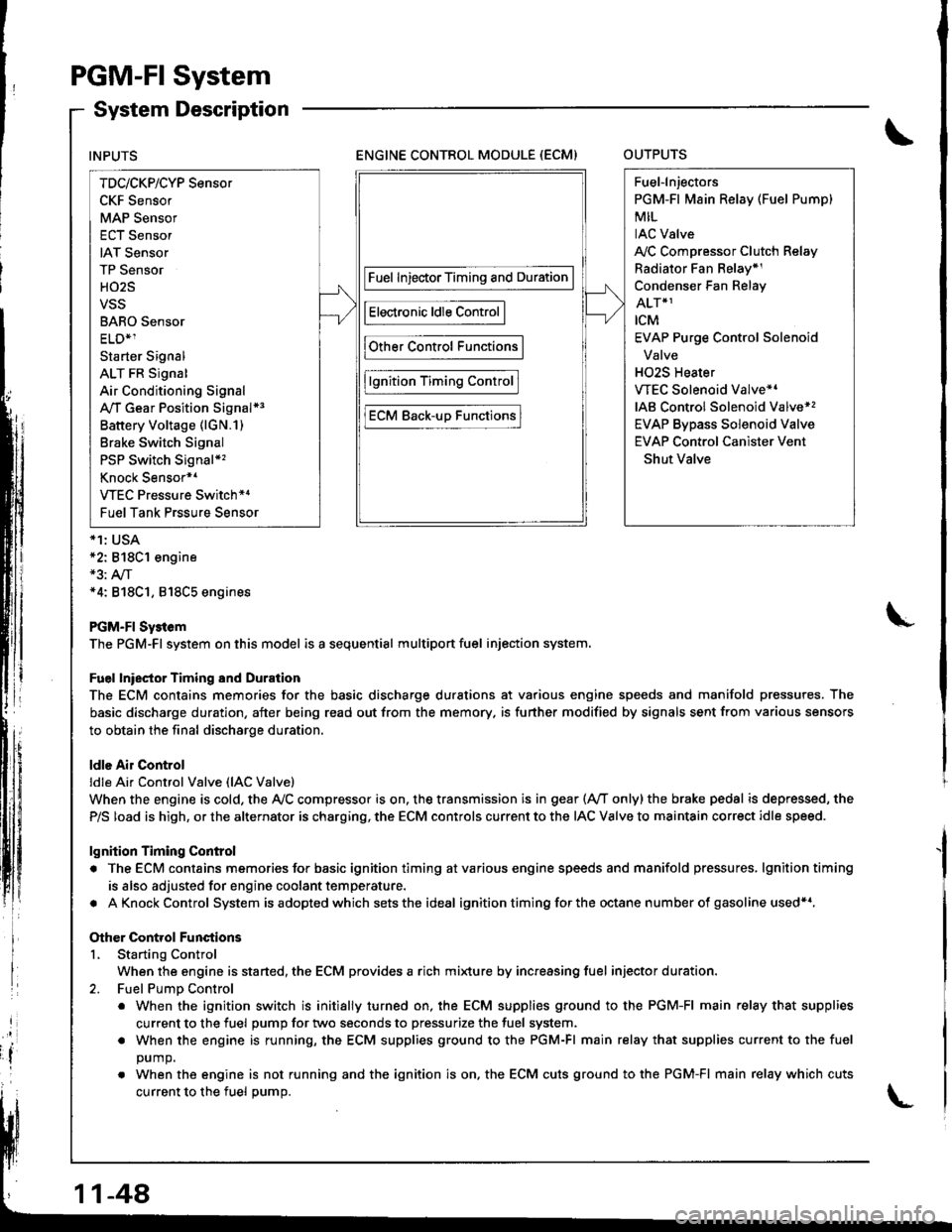
System Description
ENGINE CONTROL MODULE (ECM)OUTPUTS
*1: USA*2: 818C1 engine*3: A,/T*4: 818C1, 818C5 engines
PGM-FI Sy3tem
The PGM-Fl system on this model is a sequential multiport fuel injection system.
Fuel lniector Timing and Duration
The ECM contains memories for the basic discharge durations at various engine speeds and manifold pressures. The
basic discharge duration, after being read out from the memory. is further modified by signals sent from various sensors
to obtain the final discharge duration.
ldle Air Control
ldle Ai. Control Valve (lAC Valve)
When the engine is cold, the Ay'C compressor is on. the transmission is in gear (Ay'T only)the brake pedal is depressed, the
P/S load is high, or the alternator is charging, the ECM controls current to the IAC Valve to maintain correct idle speed.
lgnition Timing Control
. The ECM contains memories for basic ignition timing atvarious engine speeds and manifold pressures, lgnitiontiming
is also adjusted for engine coolant temperature.
. AKnockControl System isadoptedwhich sets the ideal ignition timing for the octane n um ber of gasoline used*r,
Other Control Functions
L Starting Control
When the engine is started, the ECM provides a rich mi{ure by increasing fuel injector duration.
2. Fuel PumD Control
. When the ignition switch is initially turned on, the ECM supplies ground to the PGM-FI main relay that supplies
current to the fuel pump for two seconds to pressurize the fuel system.
. When the engine is running, the ECM supplies ground to the PGM-FI main relay that supplies current to the fuel
DUmO.
. When the engine is not running and the ignition is on. the ECM cuts ground to the PGM-FI main relay which cuts
current to the fuel oumo.
INPUTS
TDc/CKP/CYP Sensor
CKF Sensor
MAP Sensor
ECT Sensor
IAT Sensor
TP Sensor
HO2S
VSS
BARO Sensor
ELD*1
Starter Signal
ALT FR Signal
Air Conditioning Signal
A,/T Gear Position Signal*3
Battery Voltage (lGN.1)
Brake Switch Signal
PSP Switch Signal*'�
Knock Sensor*1
VTEC Pressure Switch*4
Fuel Tank Prssure Sensor
Fuel InjectorTiming and Duration
Electronic ldle Control
Other Control Functions
lgnition Timing Control
ECM Back-uD Functions
Fuel-lnjectors
PGM-Fl Main Relay (Fuel Pump)
MIL
IAC Valve
A,/C Compressor Clutch Relay
Radiator Fan Belay*1
Condenser Fan Relay
ALT*1
rcM
EVAP Purge Control Solenoid
Valve
H02S Heater
VTEC Solenoid Valve*'
IAB Control Solenoid Valve*,
EVAP Bypass Solenoid Valve
EVAP Control Canister Vent
Shut Valve
11-48
Page 282 of 1680
PGM-FI System
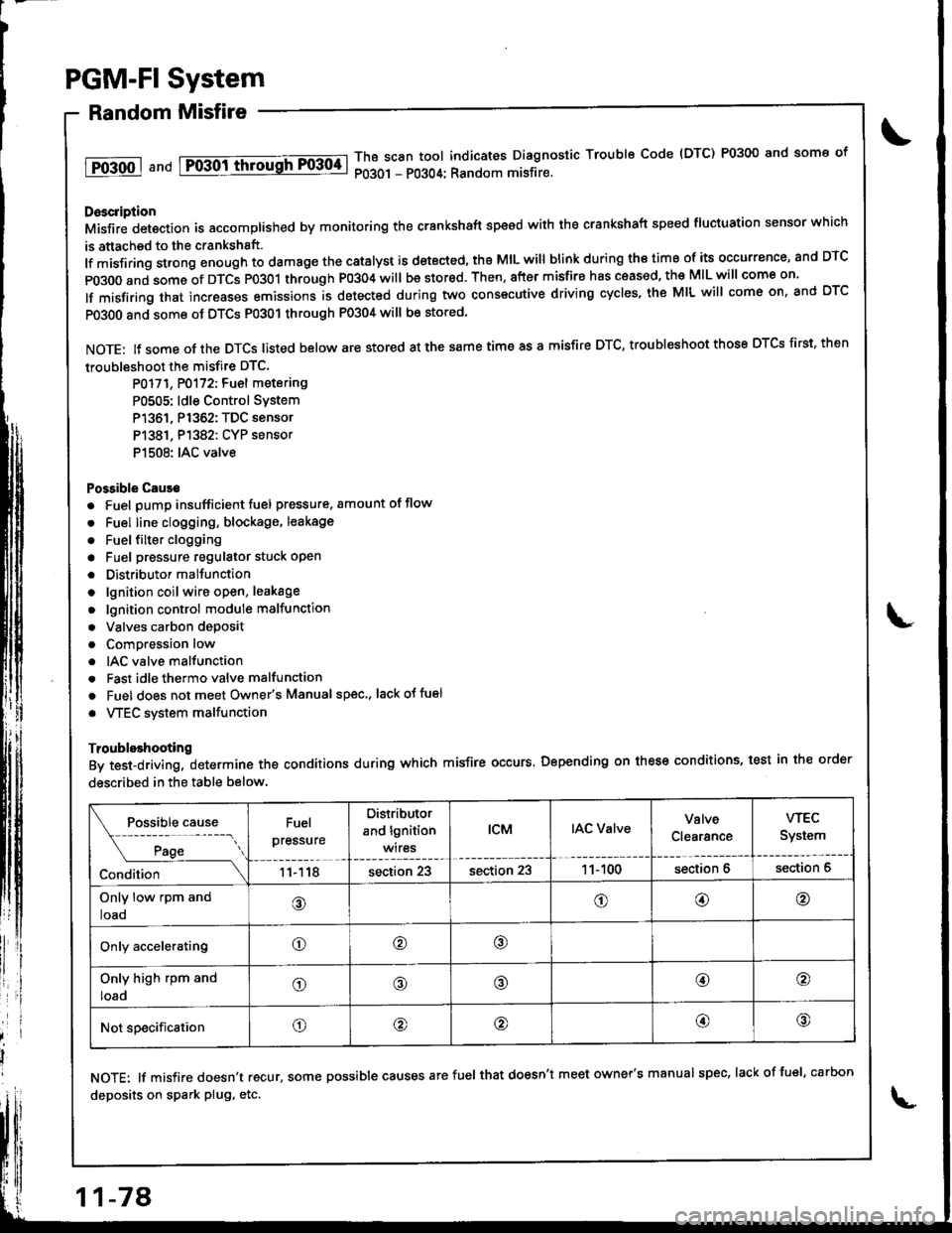
Random Misfire
1T0-500 1 a nd Fo-30ittrrousFF0304-lThB scan tool indicates Diagnostic Trouble Code {DTC) P0300 and some of
P0301 - P0304: Random misfire.
Doscription
Misfir; detection is accomplished by monitoring the crankshaft speed with the crankshaft speed fluciuation sensor which
is attached to the crankshsft.
lf misfiring strong enough to damage the catalyst is detected, the MIL will blink during iho time of its occurrence, and DTC
p0300 and some of DTCS p0301 through P0304 will be stor€d. Then, after misfire has ceased, the MIL will come on.
lf misfiring that increases emissions is detected during two consecutive driving cycles, the MIL will come on, and DTC
PO3O0 and some ot DTCS P0301 through P0304 will be stored
NOTE: lJ some of the DTCS listed below are stored at the same time as a misfire DTC, troubleshoot those DTCS first. then
troubleshoot the misfire DTC.
P0171, P0172: Fuel metering
P0505: ldle Control SYstem
P1361, P1362: TDC sensor
P1381. P1382: CYP sensor
P1508: IAC valve
Possible Cause
. Fuel pump insufficient fuel pressure. amount of flow
. Fuel line clogging, blockage, leakage
. Fuel {ilter clogging
a Fuel pressure regulator stuck open
. Distributormallunction
o lgnition coil wire open, leakage
. lgnition control module malfunction
. Valves carbon deposit
a Compression low
. IAC valve malfunction
. Fast idle thermo valve malfunction
o Fuel does not meet Owner's Manual spec., lackotfu€l
. VTEC system malfunction
Troubleshooting
By test-driving, determine the conditions during which misfire occurs. Depending on these conditions, test in the order
described in the table below.
Fuel
pressure
Distributor
and lgnition
wires
tcMIAC ValveValve
Clearance
wEc
System
11118section 23section 231 1- 100section 6section 6
Only low rpm and
loao@o@@
Only acceleratingo@o
Only high rpm and
loado@@@o
Not specificationo@@@@
NOTE: lf misfire doesn't recur, some possible causes arefuel that doesn't meet owner's manual spec, lackoffuel, carbon
deposits on spark plug, etc.
11-78
Page 283 of 1680
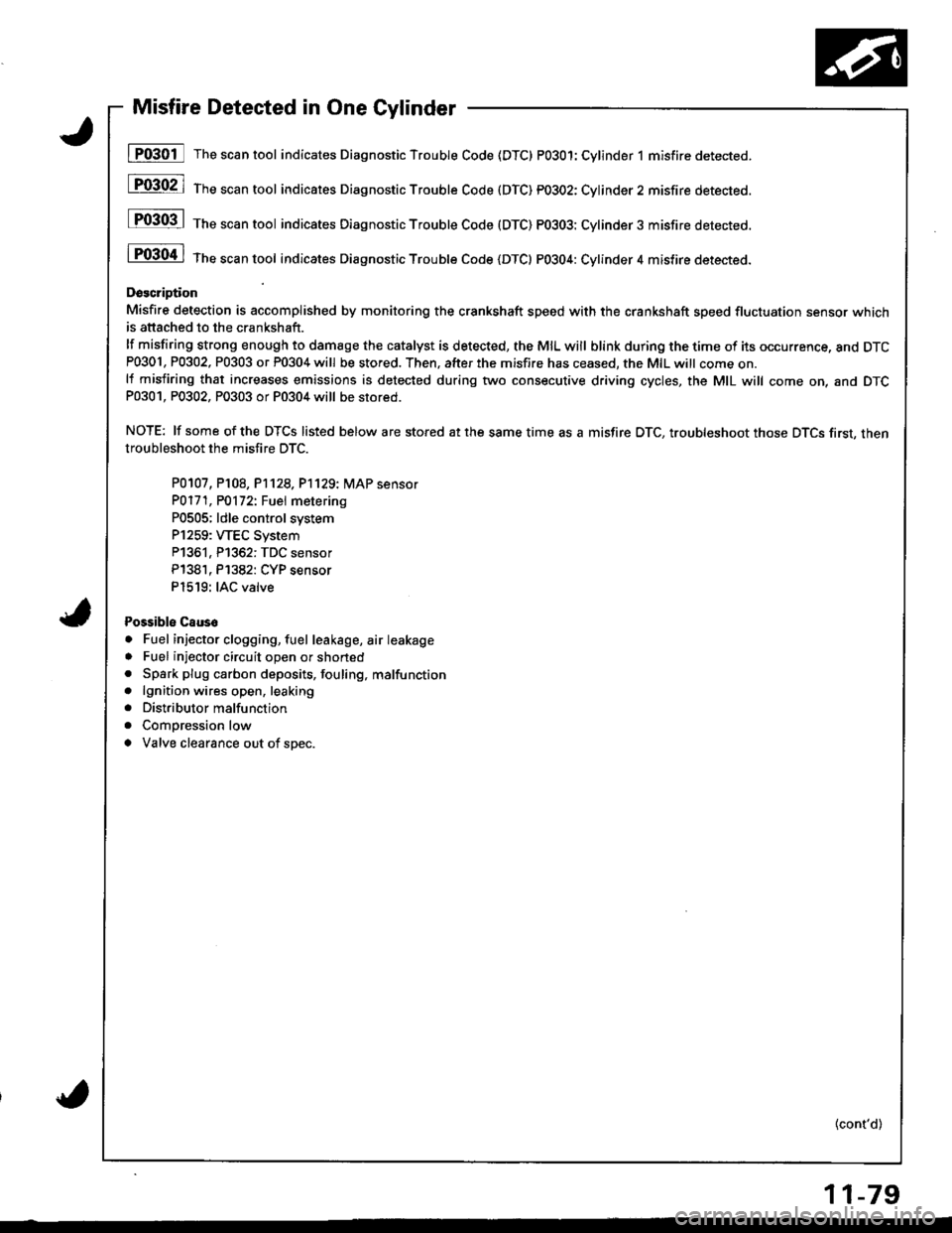
Misfire Detected in One Cylinder
I P0301 The scan tool indicates Diagnostic Trouble Code (DTC) PO3O1:Cylinder 1 misfire detected.
[F03021 1;," """n tool indicares Diagnostic Troubte Code (DTC) pO3O2: Cylinder2 misfire detected.
P0303 | ths sssn tool indicates Diagnostic Trouble Code (DTC) PO3O3: Cylinder3 misfire detected.
i P0304 | tne scan tool indicates Diagnostic Trouble code {DTC} PO3O4: Cylinder 4 misfire detected.
Doscription
Misfire detection is accomplished by monitoring the crsnkshaft speed with the crankshaft speed fluctuation sensor whichis attached to the crankshaft.
lf misfiring strong enough to damage the catalyst is detected, the MIL will blink during the time of its occurrence, and DTCP0301, P0302, P0303 or P0304 will be stored. Then, after the m;sfire has ceased, the MIL witt come on.lf misfiring that increases emissions is detected during two consecutive driving cycles, the MIL will come on, and DTCP0301, P0302, P0303 or P0304 will be stored.
NOTE: lf some of the DTCS listed below are stored at the same time as a misfire DTC, troubleshoot those DTCS first, thentroubleshoot the misfi.e DTC.
P0107, P108, P1128,P'1129:� MAP sensor
PO171, PO172t Fuel metering
P0505; ldle control system
P1259: WEC System
P1361, P1362: TDC sensor
P138'1, P1382: CYP sensor
P1519: IAC valve
Possibls Caus6
. Fuel injector clogging, fuel leakage, air leakage
. Fuel injector circuit open or shoned. Spark plug carbon deposits, fouling, malfunction. lgnition wires open, leaking
. Distributor malfunction
. Compression low
a Valve clearance out of spec.
(cont'd)
11-79
Page 287 of 1680
t@
tFffi6l
F136il
l-P1362l
Fi3BTl
tFE82-l
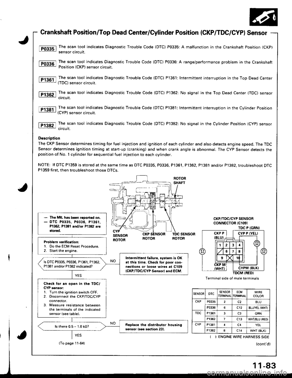
Crankshaft Position/Top Dead Center/Cylinder Position (CKP/TDC/CYPI Sensor
The scan tool indicates Diagnostic Trouble Code {DTC) P0335: A malfunction in the Crankshaft Position (CKP)
sensor circuit.
The scan tool indicates Diagnostic Trouble Code (DTC) P0336: A range/performance problem in the CrankshaftPosition (CKP) sensor circuit.
The scan tool indicates Djagnostic Trouble Code (DTC) Pl361: Intermittent interruption in the Top Dead Center(TDC) sensor circuit.
The scan tool indicates Diagnostic Trouble Code (DTC) P1362: No signal in the Top Dead Center (TDC) sensorcircuit.
The scan tool indicates Diagnostic Trouble Code (DTC) P1381: Intermittent interruption in the Cylinder Position(CYP) sensor circuit.
The scan tool indicates Diagnostic Trouble Code (DTC) P]382: No signal in the Cylinder Position (CYP) sensorcircuit.
D€scription
The CKP Sensor determines timing for fuel injection and ignition of each cylinder and also detects engine speed. The TDCSensor determines ignition timing at stan-up (cranking) and when crank angle is abnormal. The Cyp Sensor detects theposition of No. 1 cylinder for sequential fuel injection to each cylinder.
NOTE: ll DTC P1359 is stored at the same time as DTC P0335, P0336, Pl361, P1362, P1381 and/or P1382. troubleshoot DTCP1359 first, then troubleshoot those DTCS.
Problcm va.itic.lion:'1. Do the ECM Reset Procedure.2. Stan the engine.
- Th. MIL ha3 bacn r.oort.d on.- olc P0335, P0336, P1361.P1362, P1381 and/o. P1382 erottorad.
Intormittcnt tailurc, rystem is OKat this lima. Checl tor poor con-naclions or loose wire3 at C109{CKP/lDC/CYP Scn30rl rnd €CM.
ls DTC P0335, P0336, P1361, P1362.P1381 and/or P'l382 indicared?
Chcck for .n open in thc TDC/CYP ,.n3or:L Turn the ignition switch OFF.2. Disconnect the CKP/TDC/CYP
3, Measure aesistance betweenthe terminals oI the indicatedsensor {see table).
Rcplaca tho distributor hou3ingscnsor {soa soction 231,ls rhere 0.5 - 1.0 kO?
TOC P (GRN}
Termanal side of male terminals
CYP P {YELI
CYPM IBLK)
SENSOnoTcSENSORTEEMINALECMTEflMINALCOLOR
CKPP0335c2BLU
P0336c12BLU/YEL {WHTI
TDCP13613G8N
P13627c13WHT/8LU {BEO)
CYPP13814c4YEI
P1382ac14WHT (BLK)
I ): ENGINE WIRE HARNESS SIDE
(To page 11-84)
-83
Page 288 of 1680
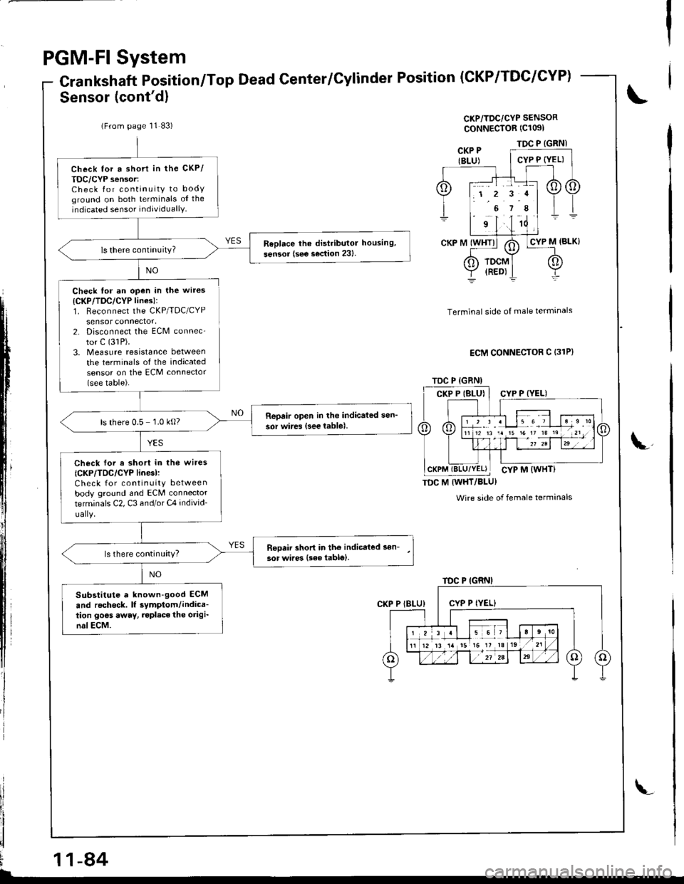
PGM-FI System
Crankshaft Position/Top Dead Center/Cylinder Position
Sensor (cont'd)
(CKP/TDC/CYP)
CKP/TDC/CYP SENSOR
ooNNECTOR (Cl091
NO
il
,ll
I
Check for an open in the wires
{CKP/TDC/CYP lines):1. Reconnect the CKP/TDC/CYPsensor connector,2. Disconnect the ECM connec-
tor C (31P).
3. Measure resrstance between
the terminals of the indicatedsensor on the ECM connector(see table).
Terminal side of male termrnals
ECM CONNECTOR C {31P}
TDC M IWHT/BLU}
Wire side of female terminals
i
ii!\
(From page 11 83)
Check tor a shott in the CKP/
TDC/CYP s6nsor:Check for continuity to bodyground on both terminals oI the
indicated sensor individuallY.
ReDlace lhe distributor housing,
sen3or {see section 23}.
Reoair open in lhe indicated sen'
sor wires {see lable).ls there 0.5 1.0 kg?
Check lor a short in the wire3
{CKP/TDC/CYP linesl:Check for continuity betweenbody ground and ECM connectorterminals C2, C3 and/or C4 individ-
ually.
Reoaii shon in tho indicated son-
3or wires {s€6 table}.ls there continuity?
Substitute a known-good ECM
and recheck. lf symptom/indica-tion go€s away, repl.ce the origi-nslECM.
TDC P {GRNI
TDC P (GRN)
1 2 r .l le 6 7
TDC P {GRN)
1 2 3 al 15 6 ,
12 13 14 t5 16 It 13
11-84
Page 296 of 1680
nsnan upeeo rlucruauon lunF, Densor lconr q,
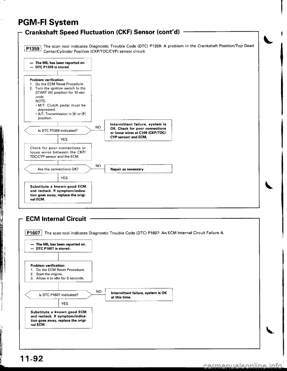
The scan tool indicates Diagnostic Trouble Code (DTC) P1359: A problem in the Crankshaft Position,Top Dead
Cenler/Cylinder Position (cKP/TDC/CYP) sensor circuit.tPr3ssl
The MIL has been reported on.DTC P1359 is stored.
Problem verilication:1. Do the ECM Reset Procedure.2. Turn the ignition switch to theSTART {lll) positaon for 10 sec'
NOTE:. M/T: Clutch pedal must be
. A/T: Transmission in E or E
Intermittent failure, svstem isOK. Check for ooor connactionsor loos€ wi.es at C109 {CKP/TDC/CYP sensorl and ECM.
ls DTC P1359 indicated?
Check for poor connections orloose wires between the CKP/TDC/CYP sensor and the ECM.
Substitute a known-good ECMand recheck. It symptom/indica-tion goes away, replace ih6 origi-nal ECM.
PGM-FI System
Crankshaft Speed Fluctuatio(CKFI Sensor (cont'd)
ECM lnternal Circuit
\
L
I P1607 Tfre scan tool indicates Diagnostic Trouble Code (DTC) Pl607: An ECM Internal Circuit Failure A.
The MIL has been reported on.DTC P16O7 is stored.
Problem verification:1. Do the ECM Reset Procedure.2. Start the engine.3. Allow it to idle {or 5 seconds.
Inte.miftent failure, systom L OKst this iimo.ls DTC P1607 indicated?
Substitute a known-good ECMand .echeck. lf symptom/indica-tion goes away, replace the origi-nalECM.
-92
Page 1150 of 1680
b-.
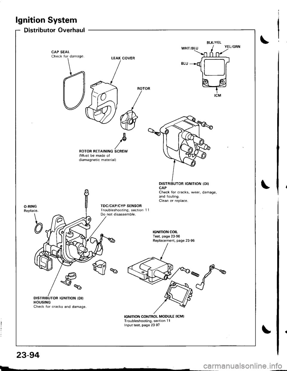
23-94
lgnition System
Distributor Overhaul
BLKi YEL
CAP SEALCheck for damage
Bp//ROTOR RETAINING SCREW(Must be made ofdaamagnetic material)
DISTRIBUTOR IGNITION (DII
CAPCheck for cracks, wear, damage,and fouling.Clean or replace.
O-RINGReplace.
\
CI
TDC/CKP/CYP SENSORTroubleshooting, sectionDo not disassemble,11
q
€a
\y%
DISTRIBUTOR IGNITION IDI)HOUSINGCheck for cracks and damage,
IGNITION CONTROL MODULE {ICMITroubleshooting, section 1 1Input test, page 23 97
LEAK COVER
l
I
I
|>l
Page 1405 of 1680
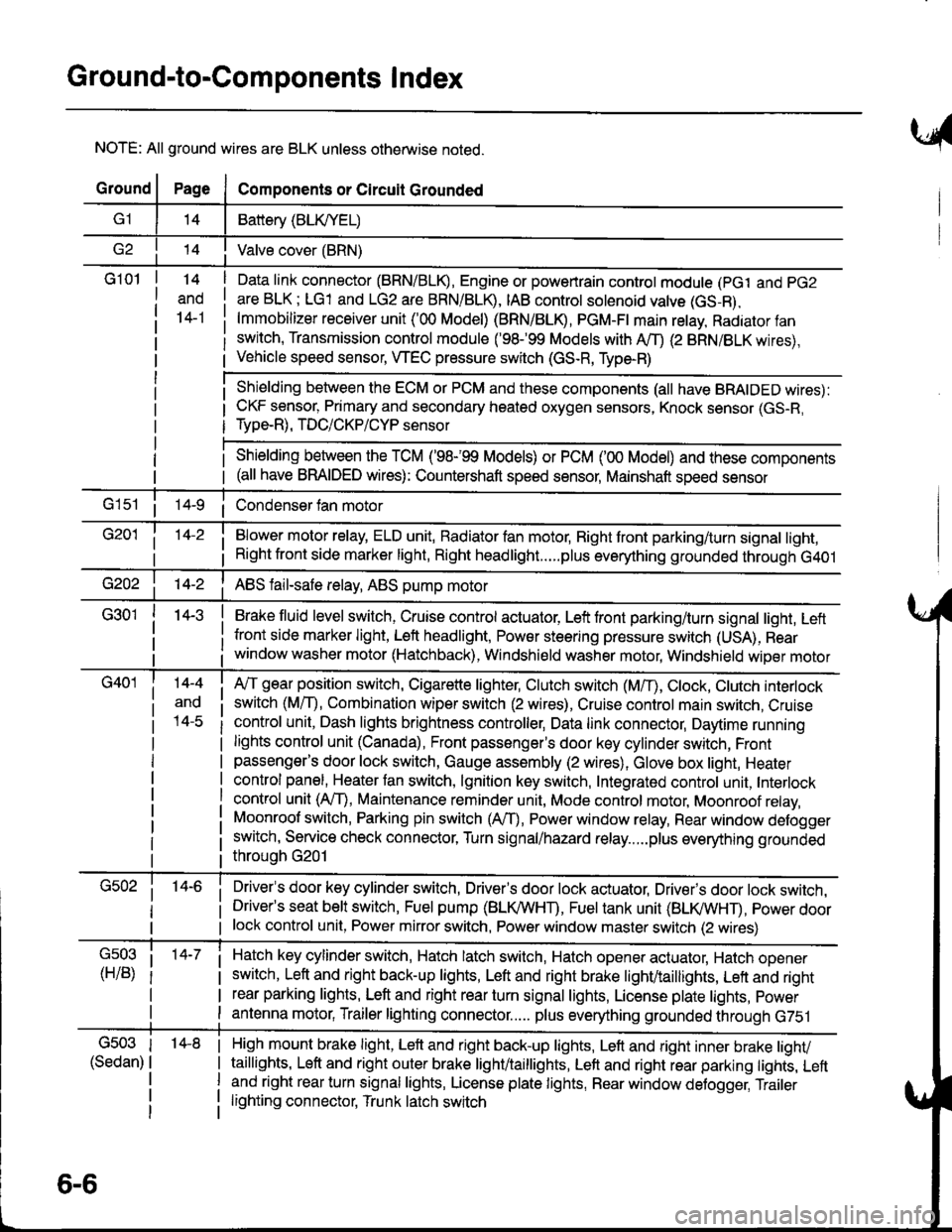
Ground-to-Components I ndex
NOTE: All ground wires are BLK unless otherwise noted.
GroundPageComponents or Circuit Grounded
Battery (BLIVYEL)
--t'I Valve cover (BRN)
G101t.+
and
14-1
Daia link connector (BRN/BLK), Engine or powertrain controt module (pct and pG2
are BLK; LG1 and LG2 are BRN/BLR, IAB controt solenoid valve (GS-B),
lmmobilizer receiver unit ('00 Model) (BRN/BLR, PGM-Ft main retay, Radiator fan
switch, Transmission control module ('98.�99 Models with MD (2 BRN/BLK wires),
Vehicle speed sensor, WEC pressure switch (GS-R, Type-R)
Shielding between the ECM or PCM and these components (all have BRAIDED wires):
CKF sensor, Primary and secondary heated oxygen sensors, Knock sensor (GS-R,
Type-R), TDC/CKP/CYP sensor
Shielding between the TCM ('98-'99 Models) or PCM ('00 Model) and these components(all have BRAIDED wires): Countershaft speed sensor, Mainshaft speed sensor
G1s1 ii Condenser fan motor
Brake fluid level switch, Cruise control actuator, Left front parking/turn signal light, Left
front side marker light, Left headlight, Power steering pressure switch (USA), Rear
window washer motor (Hatchback), Windshield washer motor, Windshield wiper motor
14-3
Blower motor relay, ELD unit, Badiator fan motor, Right front parking/turn signal light,
Right front side marker light, Right headlight.....plus everything grounded through G401
ABS fail-safe relay, ABS pump motor
G40114-4
ano
l4-c
A,/T gear position switch, Cigarette lighter, Clutch switch (M,/T), Ctock, Ctutch interlock
switch (MfD, Combination wiper switch (2 wires), Cruise control main switch, Cruise
control unit, Dash lights brightness controller, Data link connector, Daytime running
lights control unit (Canada), Front passenger's door key cylinder switch, Frontpassenger's door lock switch, Gauge assembly (2 wires), Glove box light, Heater
control panel, Heater tan switch, lgnition key switch, Integrated control unit, Interlock
control unit (AfI), Maintenance reminder unit, Mode control motor, Moonroof relay,
Moonroof switch, Parking pin switch (AfD, Power window relay, Rear window defogger
switch, Service check connector, Turn signal/hazard relay.....plus everything grounded
throuoh G201
Driver's door key cylinder switch, Driver's door lock actuator, Drivels door lock switch,Driver's seat belt switch, Fuel pump (BLI(/WHT), Fuel tank unit (BLI(/WHT), power doorlock control unit, Power mirror switch, Power window master switch (2 wires)
Hatch key cylinder switch, Hatch latch switch, Hatch opener actuator, Hatch ooener
switch, Left and right back-up lights, Left and right brake light/taillights, Lett and right
rear parking lights, Left and right rear turn signal lights, License plate lights, power
antenna motor, Trailer lighting connector..... plus everything grounded through G751
6-6
'14-8G503
(Sedan)
High mount brake light, Left and right back-up lights, Lett and right inner brake tighv
taillights, Left and right outer brake light/taittights, Left and right rear parking tights, Leftand right rear turn signal lights, License plate lights, Rear window detogger, Trailer
lighting connector, Trunk latch switch