tdc ACURA INTEGRA 1998 Service Repair Manual
[x] Cancel search | Manufacturer: ACURA, Model Year: 1998, Model line: INTEGRA, Model: ACURA INTEGRA 1998Pages: 1680, PDF Size: 53.14 MB
Page 64 of 1680
r.lJ
Valve Clearance
Adjustment
NOTE:
. Valves should be adjusted cold; at a cylinder head
temperature of less than 100'F (38"C).
Adjustment is the same for both intake and exhaust
valves.
. After adjusting, retorque the crankshaft pulley bolt to
177 N.m (18.0 kgf.m, 130 lbf'ft).
1. Remove cylinder head cover.
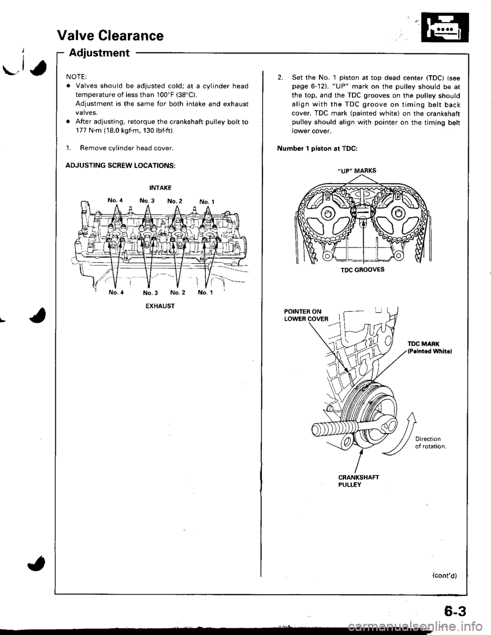
ADJUSTING SCREW LOCATIONS:
EXHAUST
(
"UP" MARKS
TDC GBOOVES
2. Set the No. 1 piston at top dead center (TDC) (see
page 6-12). "UP" mark on the pulley should be at
the top, and the TDC grooves on the pulley should
align with the TDC groove on timing belt back
cover. TDC mark (painted white) on the crankshaftpulley should align with pointer on the timing belt
lower cover.
Number 1 piston at TDC:
POINTER ONLOWER
TDC MAFK(P.inted whh.l
(cont'd)
6-3
Page 65 of 1680
Valve Clearance
Adjustment (cont'dl
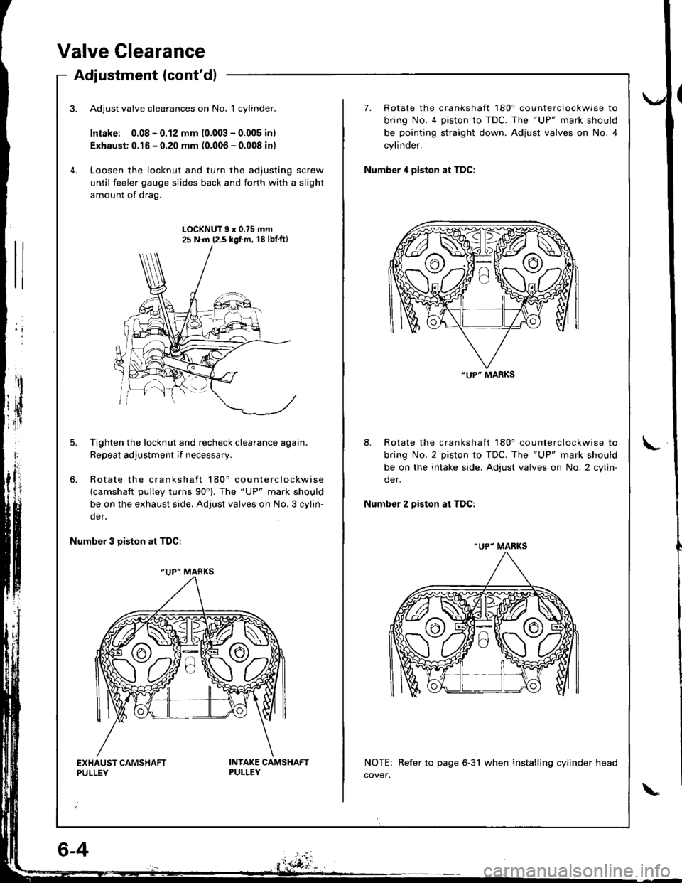
Adjust valve clearances on No. 1 cylinder.
Intske: 0.08 - 0.12 mm (0.003 - 0.005 inl
Exhaust: 0.15 - 0.20 mm (0.006 - 0.008 inl
Loosen the locknut and turn the adjusting screw
until feeler gauge slides back and forth with a slight
amount of drag.
7. Rotate the crankshaft 180' counterclockwise to
bring No. 4 piston to TDC. The "UP" mark should
be pointing straight down. Adjust valves on No. 4
cylinder.
Number 4 piston at TDC:
LOCKNUT9x0.75mm25 N.m {2.5 kgl.m, 18lbtft}
Tighten the locknut and recheck clearance again,
Repeat adjustment if necessary.
Rotate the crankshaft 180' counterclockwise(camshaft pulley turns 90'). The "UP" mark should
be on the exhaust side. Adjust valves on No,3 cylin-
der.
8. Rotate the crankshaft 180' counterclockwise to
bring No. 2 piston to TDC. The "UP" mark should
be on the intake side. Adjust valves on No. 2 cylin-
der.
Number 2 piston at TDC:
Number 3 Diston at TDC:
NOTE: Refer to page 6-31 when installing cylinder head
cover.
"UP" MARKS
"UP" MARKS
"UP" MARKS
Page 66 of 1680
Valve Seals
Replacement (cylinder head removal not required)
The procedure shown below applies when using the in-
car valve spring compressor (Snap-on YA8845 with
Y AAA45-2A 1 /8" attachment).
!@@ When using this tool, as with any tool,
always use approved eye protection. Using the
fight tool tor each job helps increase productivity
while safeguarding tools, equipment and ihe user.
Turn the crankshaft so that the No. 1 and the No. 4pistons are at top dead center (TDC).
Remove the cylinder head cover.
Remove the distributor.
Loosen and disconnect the timinq belt from the
camshaft oullevs.
5. Remove the camshaft holder bolts, then remove the
camshaft holders, the camshafts and rocker arms.
Intake Valve Seals
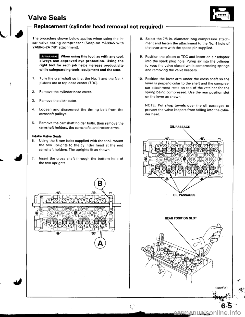
6. Using the 6 mm bolts supplied with the tool, mount
the two uprights to the cylinder head at the end
camshaft holders. The uprights fit as shown.
7. Insert the cross shaft through the bottom hole of
the two uprights.
8.
9.
10.
Select the 7/8 in. diameter long compressor attach-
ment and fasten the attachment to the No. 4 hole of
the lever arm with the speed pin supplied.
Position the piston at TDC and insen an air adaptor
into the spark plug hole. Pump air into the cylinder
to keep the valve closed while compressing springs
and removing the valve keepers.
Position the lever arm under the cross shaft so the
lever is perpendicular to the shaft and the compres-
sor attachment rests on top of the retainer for the
spring being compressed. Use the rear position slot
on the lever as shown.
NOTE: Put shop towels over the oil passages toprevent the valve keepers from falling into the cylin-
der head.
OIL PASSAGE
OIL PASSAGES
(cont'd),'.itil
i,
'6-b-'
Page 70 of 1680
\-a
I
I
{
. 6-9
Timing Belt
Inspection
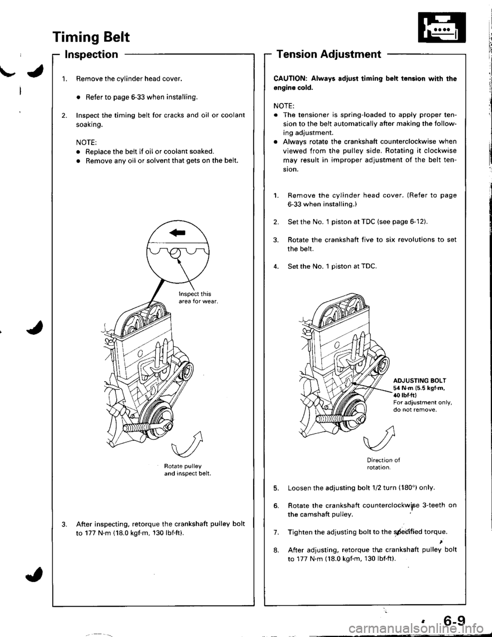
1.Remove the cylinder head cover.
o Refer to page 6-33 when installing.
Inspect the timing belt for cracks and oil or coolant
soal(n9.
NOTE:
. Replace the belt if oil or coolant soaked.
. Remove any oil or solvent that gets on the belt.
2.
Rotate pulley
and inspect belt.
After inspecting. retorque the crankshaft pulley bolt
to 177 N'm (18.0 kgf.m, 130 lbnft).
CAUTION: Always adiust iiming belt lension with the
engin€ cold.
NOTE:
. The tensioner is spring-loaded to apply proper ten-
sion to the belt automatically after making the follow-
ing adjustment.
. Alwavs rotate the crankshaft counterclockwise when
viewed from the pulley side. Rotating it clockwise
may result in improper adjustment of the belt ten-
ston.
Remove the cylinder head cover. (Refer to page
6-33 when installing.)
Set the No. I piston at TDC (see page 6-12).
Rotate the crankshaft five to six revolutions to set
the belt.
Set the No. 1 piston at TDC.
1.
2.
ADJUSTING BOLT54 N.m (5.5 kgf.m,{0 rbr.fttFor adjustment only,do not remove,
7.
8.
Direction ofrotation.
Loosen the adjusting bolt 1/2 turn (180') only.
Rotate the crankshaft counterclockwiFe 3-teeth on
the camshaft pulley
Tighten the adjusting bolt to the qdebified torque.
After adjusting. retorque the crankshaft pulley bolt
to 177 N.m {18.0 kgf.m, 130 lbf.ftl.
Page 79 of 1680
Gylinder Head
Removal (cont'dl
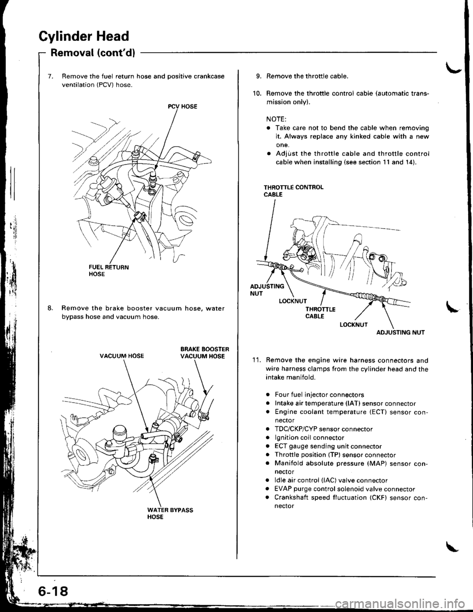
Remove the fuel return hose and positive crankcase
ventilation (PCV) hose.
Remove the brake booster vacuum hose, water
bypass hose and vacuum hose.
ltosE
VACUUM HOSE
6-18
10.
9.
11.
Remove the throttle cable,
Remove the throttle control cable (automatic trans-
mission only).
NOTE:
. Take care not to bend the cable when removing
it. Always replace any kinked cable with a new
one.
. Adjust the throttle cable and throttle control
cable when installing (s€e section 11 and 14).
THROTTLE CONTROLCABLE
ADJUSTING NUT
Remove the engine wire harness connectors and
wire harness clamps f.om the cylinder head and the
intake manifold.
Four fuel injector connectors
Intake air temperature (lATl sensor connector
Engine coolant temperature {ECT) sensor con,
nector
TDC/CKP/CYP sensor connector
lgnition coil connector
ECT gauge sending unit connector
Throttle position (TP) sensor connector
Manifold absolute pressure (MAP) sensor con-
necto r
ldle air control (lAC) valve connector
EVAP purge control solenoid valve connector
Crankshaft speed fluctuation (CKF) sensor con-
nector
a
a
a
a
a
a
a
a
ADJUSTING
Page 92 of 1680
\-
L
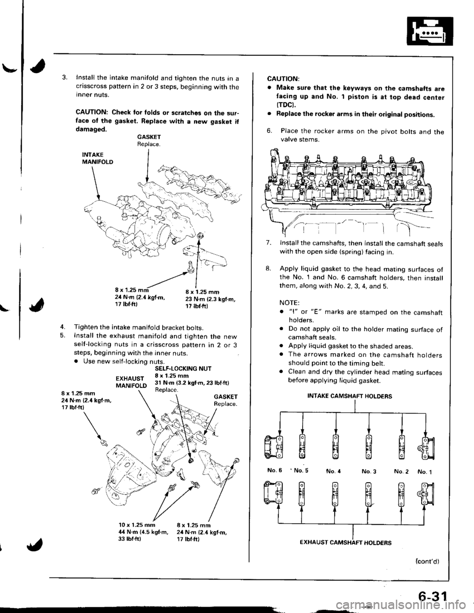
Install the intake manifold and tighten the nuts in acflsscross pattern in 2 or 3 steps. beginning with theinner nuts.
CAUTION: Check lor folds or scratches on the sur-face ol the gasket. Replace with a new gasket ildamaged.GASKETReplace.
INTAKEMANIFOLD
4. Tighten the intake manifold bracket bolts.5. Install the exhaust maniiold and tighten the newself-locking nuts in a crisscross pattern in 2 or 3steps, beginning with the inner nuts.. Use new self-locking nuts.
EXHAUSTMANIFOLD
GASKETReplace.
4
10 x 1.25 mm 8 x 1.25 mm4,{ N.rn 14.5 kgf.m, 24 N.m {2.4 kgtm,33 tbf.ftl '17 tbf.ft)
SELF.LOCKING NUT8 x 1.25 mm31 N.m (3.2 kgt m,23 lbf.ft)Replace.1 .25 mmN.m {2.4 kg{.m,rbrftt
\q
8x2417
",', r, ^-'-"-!,1,,,';-21N.m l2.1kglm, 23 N.m (2.3 ksf.m,17lbf.ftl 17 tbf.ftr
6-31
CAUTION:
. Make sure that the keyways on the camshafts aretacing up and No. 1 piston is at top dead cenier
tTDCt.. Replacethe rocker arms in their original positions.
6. Place the rocker arms on the pivot bolts and thevalve stems.
7.
8.
Install the camshafts, then install the camshaft sealswith the open side (spring) facing in.
Apply liquid gasket to the head mating surfaces otthe No. 1 and No. 6 camshaft holders, then installthem, along with No.2,3, 4, and 5.
NOTE:
. "l" or "E' marks are stamped on the camshaftholders.
. Do not apply oil to the holder mating surface ofcamshaft seals.. Apply liquid gasket to the shaded areas.. The arrows marked on the camshaft holdersshould point to the timing belt.. Clean and dry the cylinder head mating surfacesbefore applying liquid gasket.
INTAKE CAMSHAFT HOLDERS
No.6 No.5No.4No.3 No.2 No. 1
{cont'd)
Page 93 of 1680
Cylinder Head
Installation (cont'dl
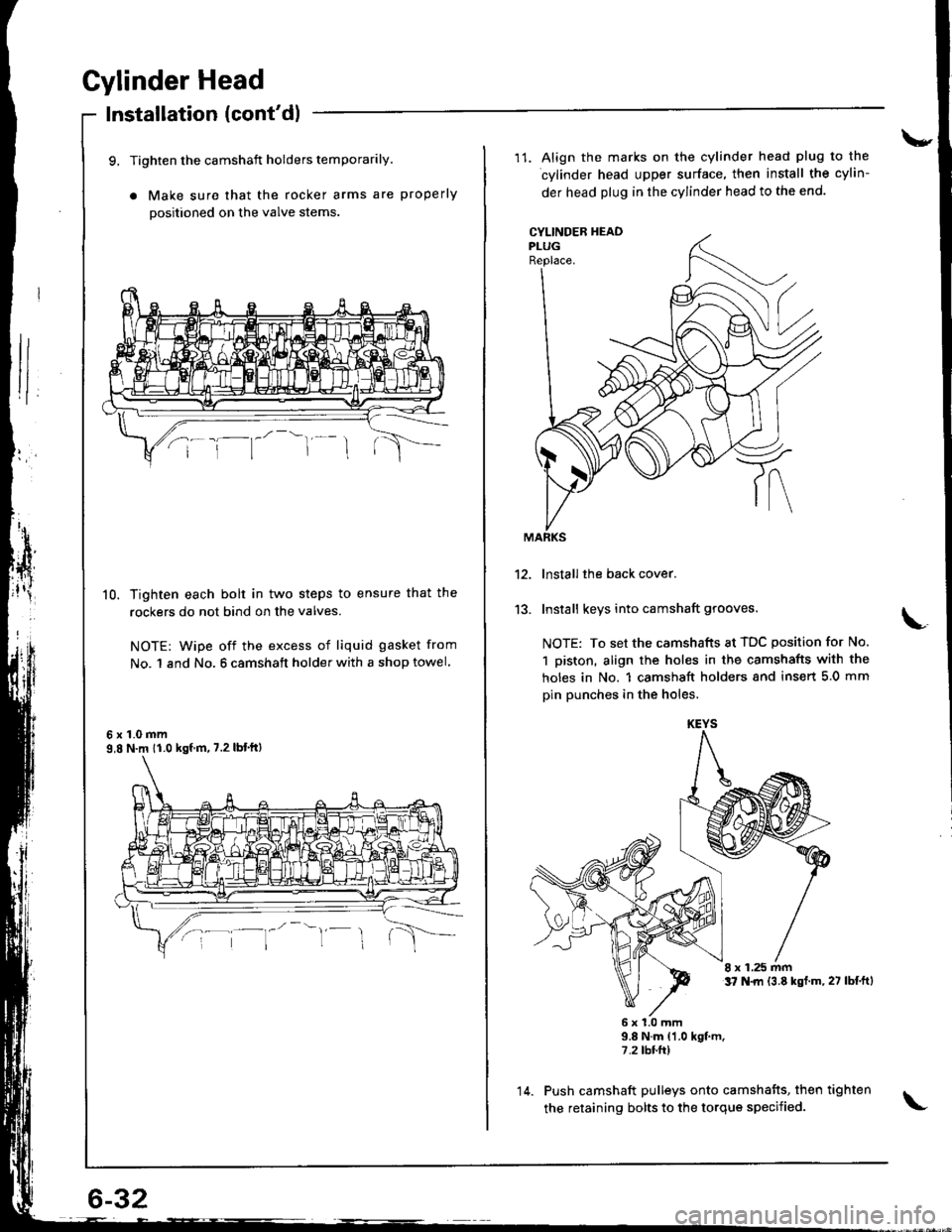
9, Tighten the camshaft holders temporarily.
a Make sure that the rocker arms are properly
positioned on the valve stems
10. Tighten each bolt in two steps to ensure that the
rockers do not bind on the valves.
NOTE: wipe off the excess of liquid gasket from
No. 1 and No. 6 camshaft holder with a shop towel
6x1.0mm9,8 N.m 11.0 kgf m, 7.2 lbt'ftl
\-
11. Align the marks on the cylinder head plug to the
cylinder head upper surface, then install the cylin-
der head plug in the cylinder head to the end.
CYLINDEB HEADPLUGReplace.
13.
lnstall the back cover.
Install keys into camshaft grooves.
NOTE: To set the camshafts at TDC position for No.
1 piston, align the holes in the camshafts with the
holes in No. 1 camshsft holders snd insert 5.0 mm
pin punches in the holes.
8 x 1.25 mmt7 N.|rl {3.8 kst.m,27 lbf.ftl
6x1.0mm9.8 N.m {1.0 kgt m.7.2 tbr.ft)
Push camshaft pulleys onto camshafts, then tighten
the retaining bolts to the torque specified.
KEYS
14.
Page 207 of 1680
Component Locations
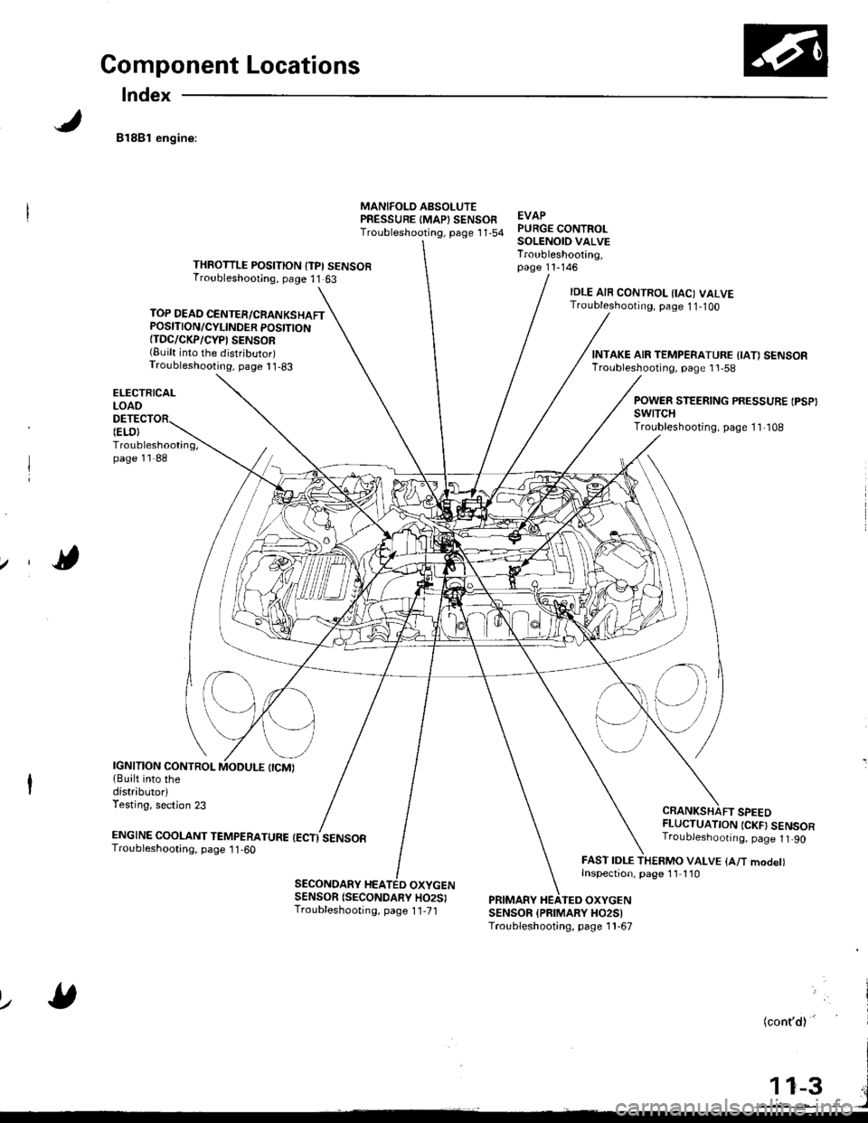
Index
81881 engine:
TOP DEAD CENTER/CRANKSHAFTPOSITION/CYLINDER POSITION{TDC/CKP/CYP' SENSOR(Built into the distributor)Troubleshooting, page I 1-83
ELECTRICALLOAO
Troubleshooting,page 11-88
MANIFOLD AsSOLUTEPRESSURE IMAP} SENSOFTroubleshooting, psge 1 '1,54EVAPPURGE CONTROLSOLENOID VALVETroubleshooting,page 11-146THROTTLE POSITION {TPI SENSORTroubleshooting, page 11 63
IELO}
IDLE AIR CONTROL IIAC) VALVETroubleshooting, page 1 1-1OO
CRANKSHAFT SPEEDFLUCTUATION {CKF} SENSORTroubJeshoonng. page 1t 90
FAST IDLE THERMO VALVE {A/T modet)Inspection, page 1'l 110
INTAKE AIR TEMPERATURE {IA1 SENSORTroubleshooting, page 1 'l -58
POWER STEERING PRESSURE IPSP}swtTcHTroubleshooting, page 1 1,108
IGNITION CONTROL{Built into thedistributorlTesting, section 23
ENGTNE cooLANT TEnapenerune {ectisensoaTroubleshooting, page 1 1 -60
SECONDARY HEATED OXYGENSENSOR (SECONDARY HO2SITroubleshooting, page 1 1-71PRIMARY HEATEO OXYGENSENSOR {PFIMARY HO2SITroubleshooting, page 1 1-67
lz
(cont'd)'
Page 208 of 1680
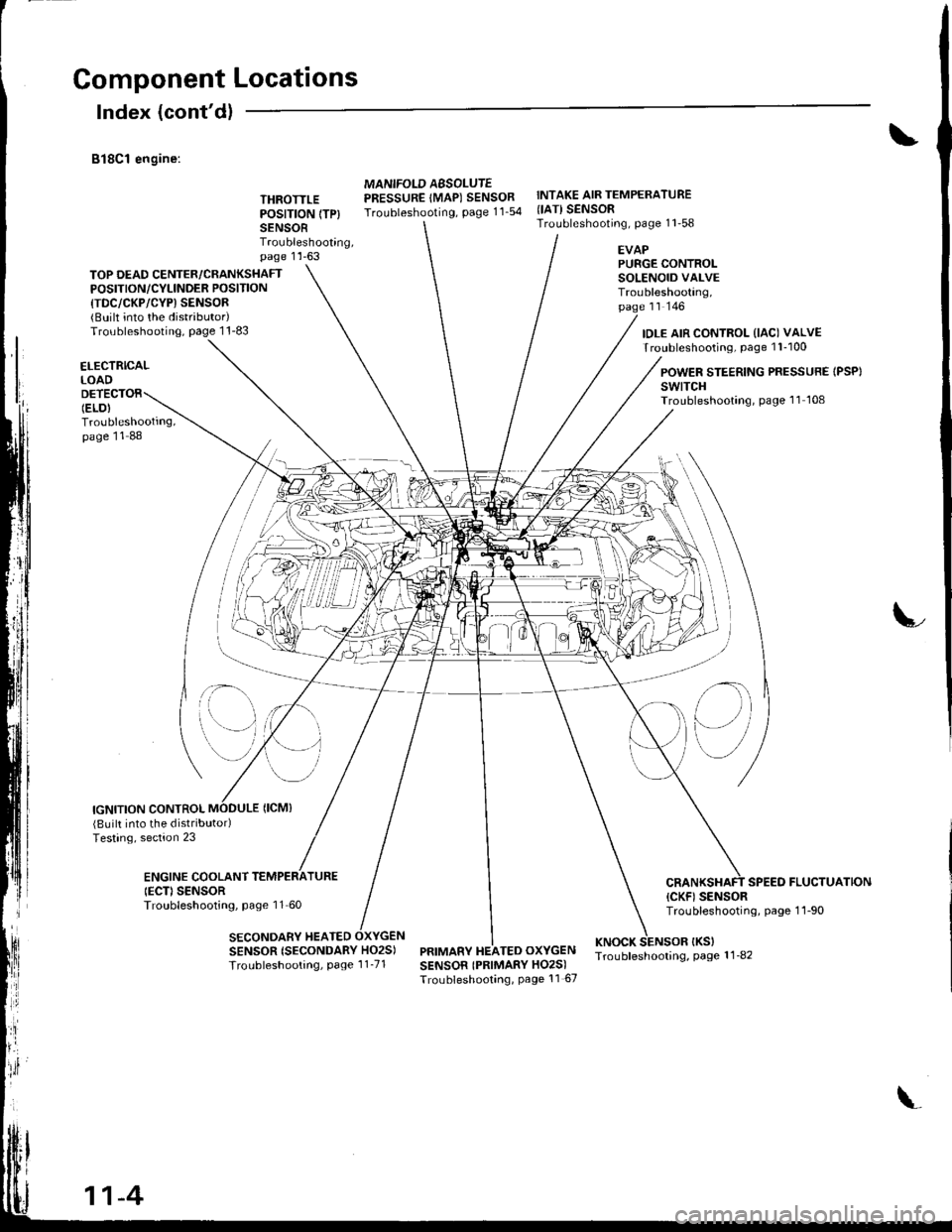
Component Locations
Index (cont'dl
B18C1 engine:
THROTTLEPOSITION (TP}
SENSORTroubleshooting,page 1 'l -63
MANIFOLD AESOLUTEPRESSURE IMAP) SENSORTroubleshooting, page 11_54
INTAKE AIR TEMPERATURE{IATI SENSORTroubleshooting, page 11'58
TOP DEAD CENTER/CRANKSHAFTPOSITION/CYLINOER POSITION
{TDC/CKP/CYP) SENSOR{BUilt into the distributor)Troubleshooting, page 1 1-83
EVAPPURGE CONTROLSOLENOID VALVETroubleshooting,page rr rqo
IDLE AIR CONTROL (IAC) VALVETroubleshooting, page 1 l-100
ELECTRICALLOAD
Troubleshooting,page 11 88
POWER STEERING PRESSURE IPSP}swtTcHTroubleshooting, page 'l1 108
IGNITION CONTROL
;- \
SENSOR {SECONDARY HO2S)
Troubleshooting, Page 1 1_71
(Built into the distributodTesting, section 23
ENGINE COOLANTIECD SENSORTroubleshooting, page 11 60
SECONDARY HEATED
SPEED FLUCTUATION(CKF) SENSORTroubleshooting, page 1 1-90
PRIMARY HEATED OXYGENKNOCK SENSOR IKSITroubleshooling, page 1 1_82SENSOR IPRIMARY HO2S)Troubleshooting, Page 11 67
il\
e)
11-4
Page 242 of 1680
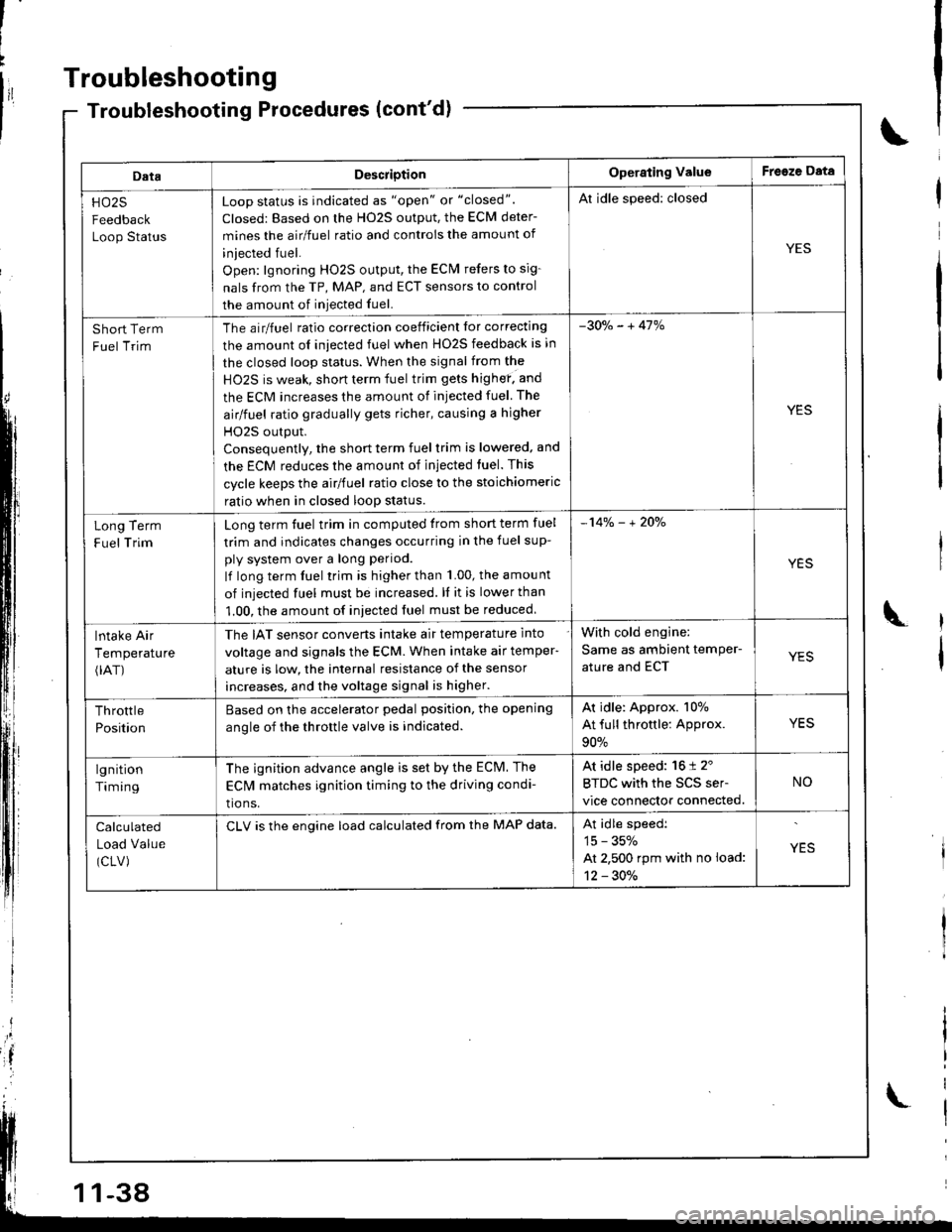
Troubleshooting
DataDescriotionOperating ValueFreeze Data
HO25
Feedback
Loop Status
Loop status is indicated as "open" or "closed".
Closed: Based on the H02S output, the ECM deter-
mines the airlfuel ratio and controis the amount of
iniected fuel.
Open: lgnoring HO2S output, the ECM refers to sig-
nals from the TP, MAP, and ECT sensors to control
the amount of iniected fuel.
Al idle speed: closed
YES
Short Term
Fuel Trim
The airlfuel ratio correclion coeificient lor correcting
the amount ol iniected fuel when HO2S feedback is in
the closed loop status. When the signal from the
HO2S is weak, short term fuel trim gets highef. and
the ECM increases the amount of injected fuel The
airlfuel ratio gradually gets richer, causing a higher
HO2S output.
Consequentlv, the short term fuel trim is lowered, and
the ECM reduces the amount of injected tuel. This
cycle keeps the airlfuel ratio close to the stoichiomeric
ratio when in closed loop status.
-30o/" - + 41%
YES
Term
Trim
Long
F uel
Long term fuel trim in computed trom short term fuel
trim and indicates changes occurring in the fuel sup-
ply system over a long period.
lf long term fuel trim is higher than 1.00, the amou nt
of injected fuel must be increased. ll it is lower than
1.00, the amount of iniected fuel must be reduced
-14% - + 2Oo/"
YES
lntake Air
Temperature(rAT)
The IAT sensor converts intake air temperature into
voltage and signals the ECM. When intake air temper-
ature is low, the internal resistance of the sensor
increases, and the voltage signal is higher.
With cold engine:
Same as ambient temPer-
ature and ECTYES
Throttle
Position
Based on the accelerator pedal position. the opening
anole of the throttle valve is indicated.
Ar idle: Approx. 107o
At full throttle: Approx.
90%
YES
lgnition
Timing
The ignition advance angle is set by the ECM. The
EClvl matches ignition timing to the driving condi-
tio ns.
At idle speed: 16 t 2'
BTDC with the SCS ser-
vice connector connected.
NO
Calculated
Load Value
(CLV)
CLV is the engine load calculated from the MAP data.At idle speedi
15 - 35%
At 2,500 rpm with no load:
12 - 30./.
YES
-38