head ACURA INTEGRA 1998 Service Owner's Manual
[x] Cancel search | Manufacturer: ACURA, Model Year: 1998, Model line: INTEGRA, Model: ACURA INTEGRA 1998Pages: 1680, PDF Size: 53.14 MB
Page 183 of 1680
3.
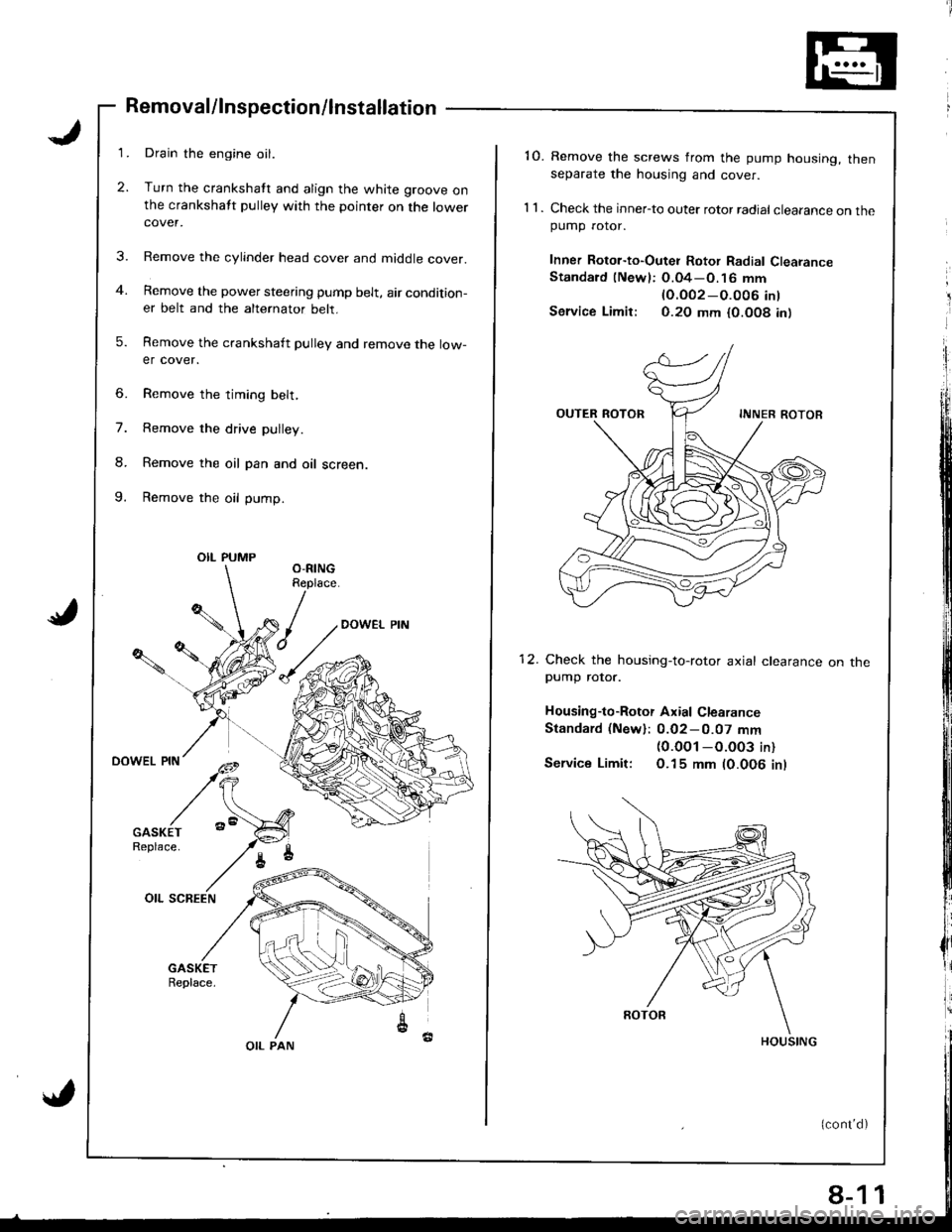
Removal/lnspection/lnstallation
Drain the engine oil.
Turn the crankshatt and align the white groove onthe crankshatt pulley with the pointer on the lowercover.
Remove the cylinder head cover and middle cover.
Remove the power steering pump belt, air condition-er belt and the alternator belt.
Remove the crankshaft pulley and remove the low-er cover.
6. Remove the timing belt,
7. Remove the drive pulley.
8. Remove the oil pan and oil screen.
9. Remove the oil pump.
OIL PUMP
OIL PAN
8-1
'10. Remove the screws from the pump housing, thenseparate the housing and cover.
1 1 . Check the inner-to outer rotor radial clearance on thepumD rotor.
Inner Rotor-to-Outei Rotor Radial ClearanceStandard (Newl: O.04-O.16 mm
lO.OO2-O.O06 int
Service Limir: 0.20 mm {0.O08 in)
12. Check the housing-to-rotor axial clearancepump rotor.
Housing-to-Rotor Axial Clearance
Standard (New): 0.02-0.07 mm(0.0O1 -O.003 in)
Service Limit: O.15 mm (0.006 inl
on tne
1
Page 244 of 1680
I
t
h,,l,!
il
Troubleshooting
ECM CONNECTOR {31P)
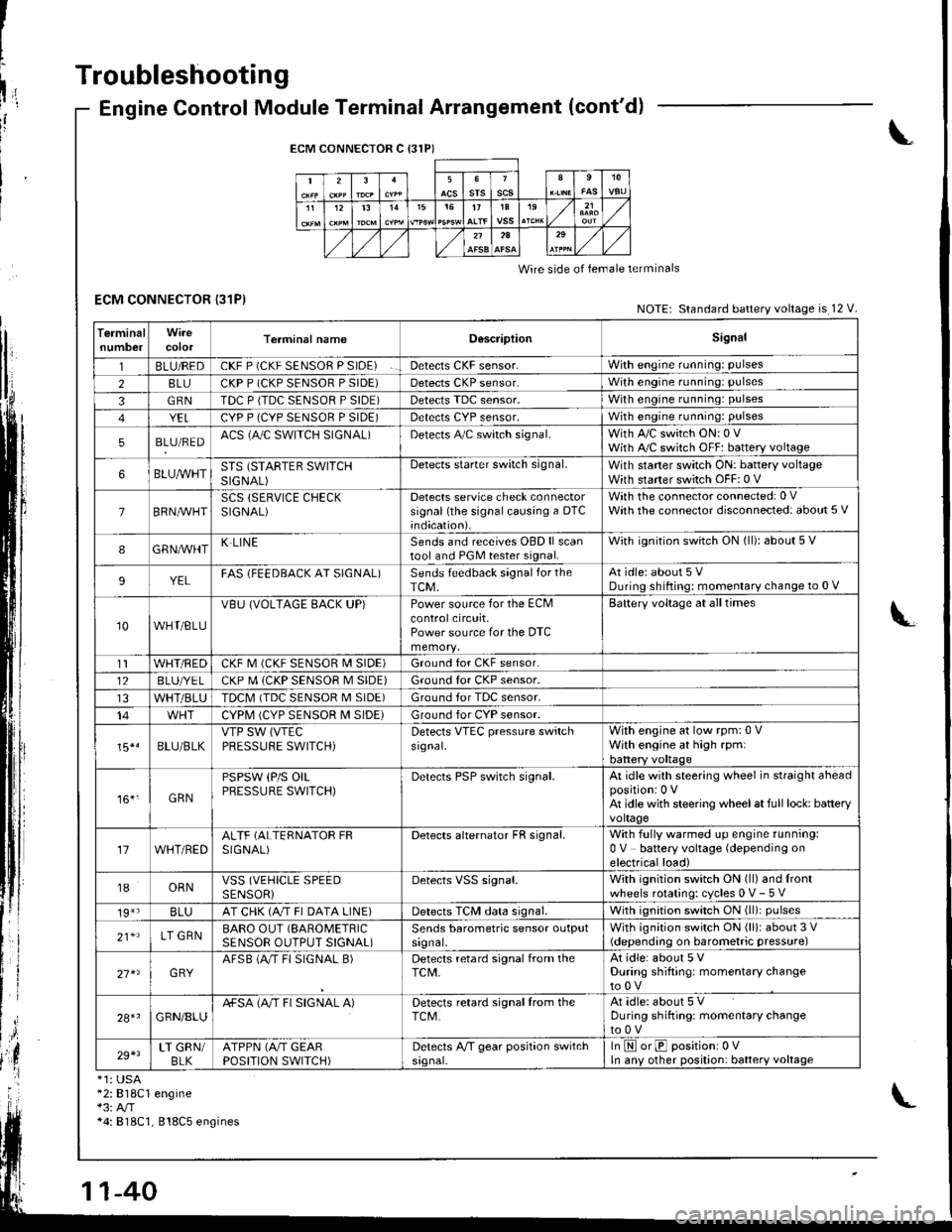
Engine Control Module Terminal Arrangement (cont'd)
ECM CONNECTOR C {31P)
235srsscs1112t31515t71A19
2A
Wire side of lemale terminals
NOTE: Standard battery voltage is 12 V.
TerminalnumbercolorTerminal namoD6scriptionSignal
1BLU/REDCKF P (CKF SENSOR P SIDE)Detects CKF sensor.With engine running: pulses
28LUCKP P (CKP SENSOR P SIDE)Detects CKP sensor.With engine running: pulses
3GRNTDC P {TDC SENSOR P SIDE)Detects TDC sensor,With engine running: pulses
YELCYP P (CYP SENSOR P SIDE)Detects CYP sensor,With engine running: pulses
5BLU/REDACS (AJC SWITCH SIGNAL)Detects A,/C switch signal.With A,/C switch ON: 0 VWith A,/C switch OFF: battery voltage
6BLUA/VHTSTS (STARTEB SWITCHSIGNAL)
Detects starter switch signal.With staner switch ON: battery voltageWith starter switch OFF: 0 V
7BRN,AiVHTSCS (SERVICE CHECKSIGNAL)Detects service check connectorsignal (the signalcausing a DTC;ndication).
With the co n nector con nected: 0 VWath the connector disconnected: about 5 V
8GRNAVHTK LINESends and receives OBD ll scantool and PGM tester signal.With ignition switch ON (ll): about 5 V
9YELFAS lFEEDBACK AT SIGNAL)Sends feedback signal for theTCM,At idle: about 5 VDuring shifting: momenlary change to 0 V
10WHT/BLU
VBU (VOLTAGE BACK UP)Power source for the ECMcontrolcircuit,Power source for the DTC
Battery voltage at all times
t1WHT/REDCKF M (CKF SENSOR I\4 SIDE)Ground for CKF sensor.
12BLUI/E LCKP M (CKP SENSOR M SIDE)Ground for CKP sensor.
WHT/BLUTDCM (TDC SENSOR M SIDE)Ground tor TDC sensor.
14CYPM (CYP SENSOR M SIDE)Ground for CYP sensor.
15*.BLU/BLKVTP SW (VTEC
PRESSUFE SWITCH)Detects VTEC pressure switchsr9nal.
With engine at low rpm:0 VWith engine at high rpmlbattery voltaqe
161,GRN
PSPSW (P/S OILPRESSURE SWITCH)Derecls PSP switch signal.At idle with steering wheel in straight aheadpositioni 0 VAt idle with steering wheelat full lock: batteryvoltage
17WHT/REDALTF (ALTERNATOR FRSIGNAL)Detects alternator FR signal.With fully warmed up engine running:0 V battery voltage (depending onelectrical load)
18ORNVSS (VEHICLE SPEEDSENSORiDetects VSS signal.With ignition switch ON (ll) and lrontwheels rotating: cycles 0 V- 5 V
19*3BLUAT CHK (A/T FI DATA LINE)Detects TCM data signal.With ignition switch ON (ll)i pulses
21*LT GRNBARO OUT (SAROMETRIC
SENSOR OUTPUT S!GNAL)Sends barometric sensor outputsrgnal,With ignition switch ON (ll): about 3 V(depending on barometric pressure)
27 x3GRYAFSB (A"/T FI SIGNAL B)Detects retard signal from theTCM,At idle: about 5 VDuring shifting: momentary changeto0V
28+1GRN/8LUA+SA (A/T FI SIGNAL A)Detects retard signal from theTCM.At idle: about 5 VDuring shifting: momentarV changeto0V
29+3LT GRN/BLKATPPN (A/T GEARPOSITION SWITCH)Detects A,/T gear position switchsrgnal-In E orE positionr 0VIn anv other position: battery voltage
*1: USA*2:818C1 engine*3: A/T*4: 818C1, 818C5 engines
Page 245 of 1680
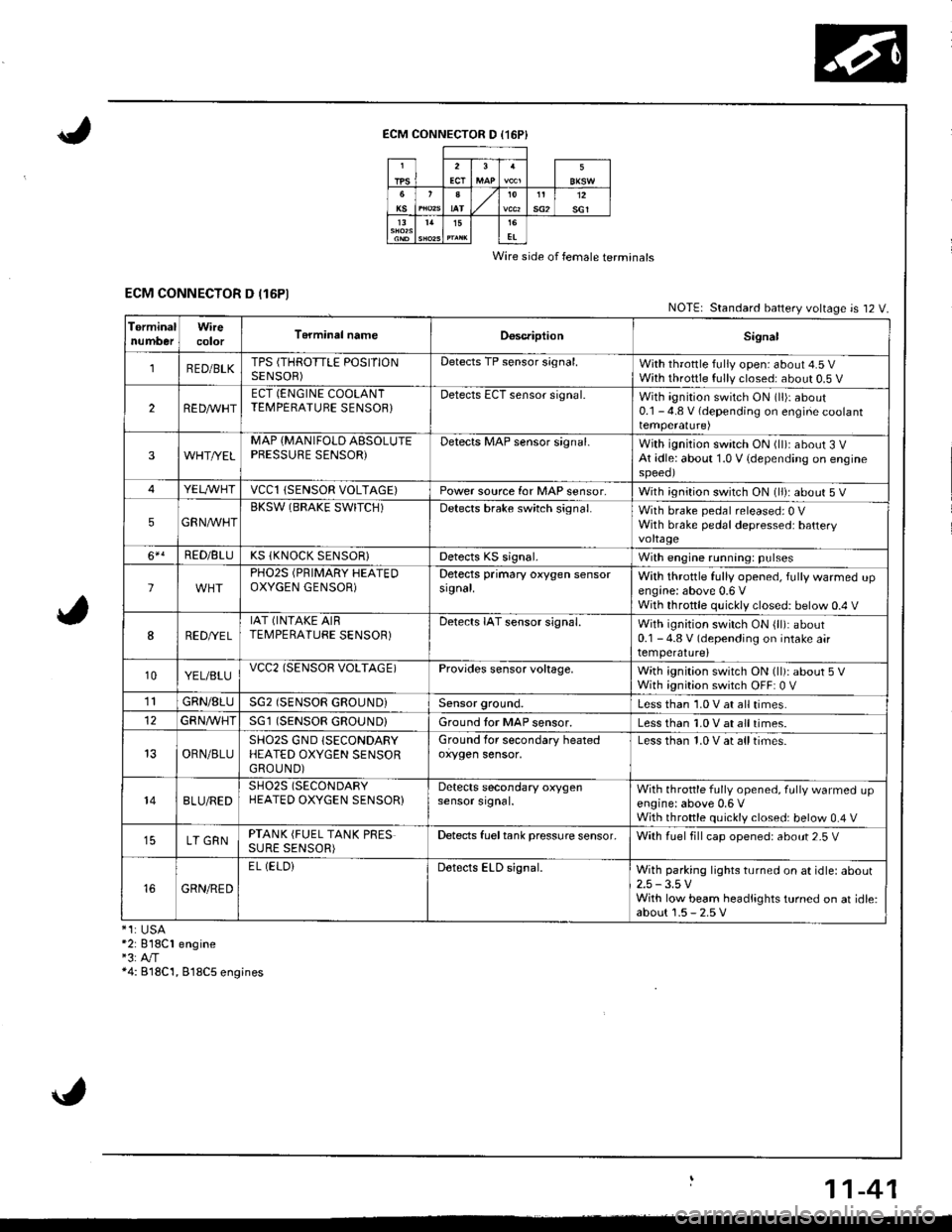
ECM CONNECTOR D (16P}
Wire side of female terminals
ECM CONNECTOR D (16P1NOTE| Standard battery voltage is 12 V.
TerminalnumberWirecolorT6rminal nameDoscriptionSignal
1RED/BLKTPS (THROTTLE POSITIONSENSOR)Detects TP sensor s;gnal.With throttle fully open: about 4.5 VWith throttle fully closed: about 0.5 V
2REDAr'r'HTECT (ENGINE COOLANTTEMPERATUBE SENSOB}Detects ECT sensor signal.With ignition switch ON (ll)r about0.1 - 4.8 V (depending on engine coolanttemperalure)
3WHT//ELMAP {MANIFOLD AESOLUTEPBESSURE SENSOR)Detects MAP sensor signal.With ignition switch ON (ll)iabout 3 VAt idle: about 1.0 V {depending on enginespeeol
4YELA/VHTvccl{SENSOR VOLTAGE)Power source for MAP sensor,With ignition switch ON (ll): about 5 V
5GRNAVHTBKSW (BRAKE SWITCH)Detects brake switch signal.With brake pedal released: 0 VWith brake pedal depressed: batteryvoltage
6*!RED/BLUKS (KNOCK SENSOR}Detects KS signal.With engine running: pulses
lPHO2S (PRIMARY HEATEDOXYGEN GENSOR)Detects primary oxygen sensorsignal.With throttle fully opened, fully warmed upengine: above 0.6 VWith throttle quickly closed: below 0.4 V
8RED/VEL
IAT (INTAKE AIRTEMPERATURE SENSOR)Detects IAT sensor signal.With ignition switch ON {ll): about0.1 - 4.8 V (depending on intake airtemperature)
10YEL/BLUvcc2(SENSOB VOLTAGE)Provides sensor voltage,With ignition switch ON (ll): about 5 VWith ignition switch OFF: 0 V
1lGRN/8LUSG2 (SENSOR GROUND}Sensor ground.Less than 1.0 V at all times.
GFNA/VHT(SENSOR GROUND}Ground tor MAP sensor.Less than 1.0 V at all times.
OBN/BLUSHO2S GND (SECONDARY
HEATED OXYGEN SENSORGROUND)
Ground for secondary heatedoxygen sensor,Less than 1.0 V at alltimes.
148LU/REDSH02S (SECONDARY
HEATED OXYGEN SENSOR}Detects secondary oxygensensor srgnal.With throttle fully opened. fully warmed upengine: above 0,6 VWith throttle quickly closed: below 0.4 V
LT GRNPTANK (FUEL TANK PRESSURE SENSOR)Detects fueltank pressure sensor.With luel fill cap opened: about 2-5 V
GRN/RED
EL (ELOiDetects ELD signal.With parking lights turned on at idle: about2.5 -3.5 VWith low beam headlights turned on at idle:about 1.5 - 2.5 V*1:USA*2: 818C1 engine"3:A"/T*4: B18C'1, 818C5 engines
11-41
Page 292 of 1680
PGM-FI System
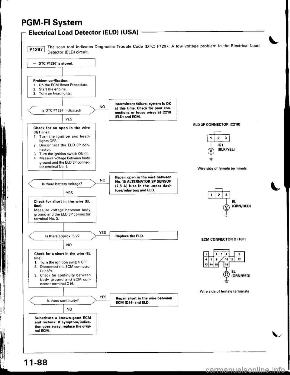
Electrical Load Detector (ELDI (USAI
The scan tool indicates Diagnostic Trouble Code (DTC) P1297: A low voltage problem in the Electrical Load
Detector (ELD) circuit.
ELD 3P CONNECTOR {C218)
Wire side of female termin€ls
Problem verification:1- Do the ECM Reset Procedure.2. Stan the engine.3. Turn on headlights.
Int€rmittont failure. swtom b OKat this time. Check tor poor con-neqtions or loose wi.es at C218IELDI and ECM-
ls DTC P1297 indicated?
Check for ao open in the wire
{lG1 linel:1. Turn the ignition and head-lights OFF.2. Disconnect the ELD 3P con-nector,3. Turn the ignition switch ON (ll).
4. Measure voltage betlveen bodyground and the ELD 3P connector te.minal No.'1.
Repair op6n in the wire baiwe€nNo. 15 ALTERNATOR SP SENSOR17.5 Al fus€ in the under-dashluse/relay box and ELD.
Chock lor short in the wire {ELline,:Measure voltage between bodyground and the ELD 3P connectorterminal No.3.
ls there approx. 5 Vl
Check for a short in the wire (EL
linel:1. Turn the ignition switch OFF.2. Disconnect the ECM connectorD (16P).
3. Check for continuity betweenbody ground and ECM con-nector terminal D16.
Sooair short in the wire betweenECM (D161 and ELD.
Substitut€ a known-9ood ECMand recheck. It symptom/indica-tion goes away, r€place the origi-nal ECM.
EL{GRN/REDI
ECM CONNECTOR D {16PI
Wire side oI Iemale tarminals
11-88
Page 293 of 1680
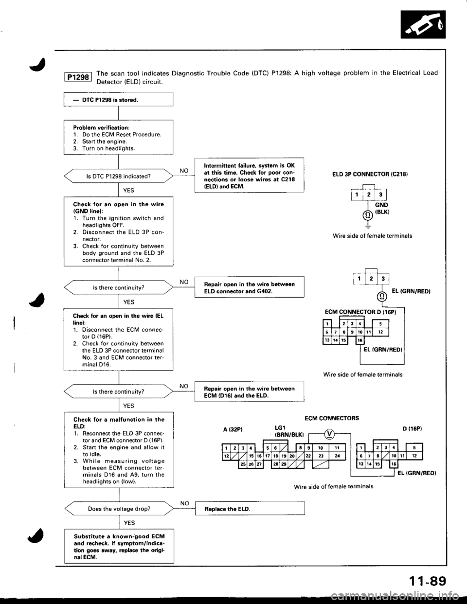
The scan tool indicates Diagnostic Trouble Code (DTC) P1298: A high voltage problem in the Electrical Load
Detector (ELD) circuit.
ELD 3P CONNECTOR {C218}
_rJ ,112 3l-f-dnD
Wire side of female terminals
ECM CONNECTORS
{BLKI
Wire side of female termin6ls
EL {GRN/REDI
ECM CONNECTOR D (16PI
P.oblem verification:l� Do the ECM Reset Procedure.2. Start the engine.3. Turn on headlights.
lntermittent failure, 3vstem is OKel ihis time. Chock for ooor con-nections or loose wiros at C218(EtD) and ECM.
ls DTC P1298 indicated?
Check lor an open in the wire(GNO linel:1. Turn the ignition switch andheadlights OFF.2. Disconnect the ELD 3P con-nector.3. Check for continuity betweenbody ground and the ELD 3Pconnector terminal No. 2.
Bepair opon in the wire bstweenELO connector and G402.
Check tor an opon in the wire IELlinell1. Disconnect the ECM connec-tor D (l6Pi.
2. Check for continuity betweenthe ELD 3P connector terminalNo. 3 and ECM connector terminal D16.
Repair open in the wir€ betweenECM l016l and rhe ELD.ls there continuity?
Check for a malfunction in theELD:1. Reconnect the ELD 3P connec-tor and ECM connector D (16P).
2. Start the engine and allow itto idle.3. Wh ile measuring voltagebetween ECM connector terminals D16 and A9, turn theheadlights on {low).
Sub3titute a knownjgood ECMand rechock. lf 3vmptom/indics-tion 9oe6 away, replace the original ECM.
A l32PtIBRN/BI-KI
Wire side of female ierminals
1 1-89
Page 302 of 1680
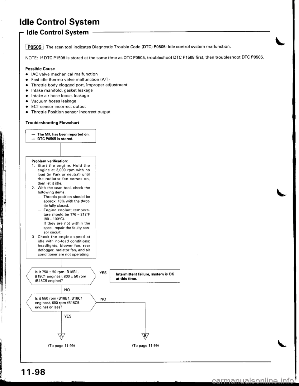
ldle Control System
ldle Control System
i P0505 | fne scan tool indicates Diagnostic Trouble Code (DTC) P0505: ldle control system malfunction,
NOTE: ll DTC Pl508 is stored at the same time as DTC P0505, troubleshoor DTC P1508 first. then troubleshoot DTC P0505.
Possible Cause
. IAC valve mechanical malfunctiorr
. Fast idle thermo valve malfunction (A"/T)
. Throttle body clogged port, improper adjustment
. Intake manifold, gasket leakage
. Intake air hose loose, leakage
a Vacuum hoses leakage
. ECT sensor incorrect output
. Throttle Position sensor incorrect output
Troubleshooting Flowchart
Problem verification:1. Start the engine. Hold theengine at 3,000 rpm wath noload 1in Park or neutral) untilthe radiator fan comes on,then let it idle.2. With the scan tool, check thefollowing items.- Throttle position should beapprox. 10% with the throttle fully closed.Engine coolant tempera-ture should be 116 212F(80 - 100'c).lf they are not within thespec., repair the faulty sensor crrcuft,3 Check the engine speed atidle with no-load conditions:headlights, blower fan, reardefogger, radiator fan, and airconditioner are not operating,
- The MIL has been reported on.- DTC P0505 is stored.
ls it 750 t 50 rpm (81881,
818C1 engines), 800 I 50 rpm(818C5 engine)?
Intermittent failur6, svstsm is OKat this tim€.
ls it 550 rpm (81881,818C1
engines), 600 rpm {818C5enginelor less?
-98
(To page 11'99)(To page 11-99)
Page 305 of 1680
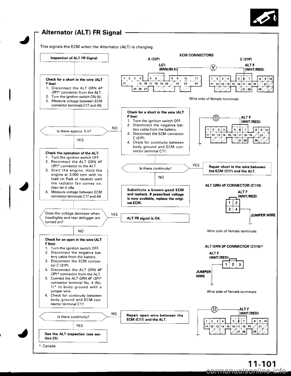
This signals the ECM when the Alternator (ALT) is charging.
Alternator (ALT) FR Signal
Check lor a short in th€ wire {ALTF line):1. Oisconnect the ALT GRN 4P(3P)* connector from the ALT.2. Turn the ignition switch ON {ll).3. Measure voltage between ECMconnector terminals C17 and A9.
ECM CONNECTORSA t32Pt
LG1
c 13lPl
ALT F(WHT/FEDI
Wire side of female terminals
ALT GRN 4P CONN€CTOR {C119}
JUMPER WIRE
Wire side of female terminals
ALT GRN 3P CONNECTOB {C119)*
JUMP€RWIRE
Wire side ot female terminals
12 15 t6 rr t8 19I
?
oALT F(WHT/REOI
23aI10
t112t3t5l6r819 ,/21
./,/,/2a29
[,ALT FIWHT/RED)
12339
11 12l517 tla19 ,/21
Inspection of ALT FR Signal.
Check for a shon in the wire {ALTF line):1. Turn the ignition switch OFF.2. Disconnecl the negative baatery cable from the battery.3. Disconnect the ECM connectorc (31P).
4. Check for continuity betweenbody ground and ECM con-nector terminal C17.
ls there approx.5 V?
Check the operation ofthe ALT:1. Turn the;Onition switch OFF-2. Reconnect the ALT GRN 4P(3P)* connector to the ALT.3. Start the engine. Hold theengine at 3,000 rpm wkh noload {in Park or neutral) untilthe radiator fan comes on,then let it idle.4. Measure voltage bet/veen ECMcon nector termina ls C17 and A9.
Ropair short in the wir6 betweenth6 ECM (C17) and the ALT.
Substitute a known-good ECMand recheck. It prescribed voltagGis now available, replace th€ origi-nal ECM.
Does the voltage decrease whenheadlights and rear defogger areturned on?ALT FR signal is OK.
Check tor an open in the wire {ALTF line):1. Turn the ignition switch OFF-2. Disconnect the negative bat-tery cable from the battery.3. Disconnect the ECM connector C (31P).
4. Disconnect the ALT GRN 4P(3Pi* connector from the ALT.5. Connect the ALT GRN 4P (3p)*
connector terminal No. 4 (No.'l)* to body ground with a
6. Check for continuity betweenbody ground and ECM connector terminal C17.
Ropair open wire bstw€an theECM {C17} and rhe ALT.ls there continuity?
ri Canada
11-101
Page 315 of 1680
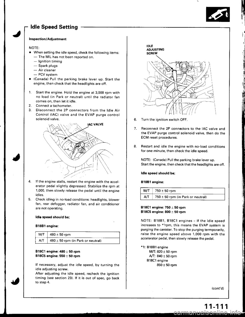
ldle Speed Setting
IDLEADJUSTINGSCREW
7.
6.Turn the ignition switch OFF.
Reconnect the 2P connectors to the IAC valve and
the EVAP purge control solenoid valve, then do the
ECM reset procedures.
Restart and idle the engine with no-load conditions
for one minute, then check the idle speed.
NOTE: (Canada) Pullthe parking brake lever up.
Start the engine, then check that the headlights are off.
ldle speed should be;
Bl88l €ngine:
Mfi750 i 50 rpm
A/T750150 rpm (in Park or neutral)
818C1 engine:750 i 50 rpm
818C5 engine: 800 i 50 rpm
NOTE: 81881, Bl8Cl engines - It the idle speed
increases to *1rpm, this means the EVAP system ispurging the canister. To stop the purging termporarily.
raise the engine speed above 1,000 rpm with the
accelerator pedal, then slowly release the pedal.
*1: 81881 engine
M/T: 820 i 50 rpm
Ay'T: 840 t 50 rpm
818Cl engine
850 I 50 rpm
(cont'd)
Inspection/Adiustmont
NOTE:
. When setting the idle speed, checkthe following items:- The MIL has not been reported on.- lgnition timing
Spark plugs- Air cleaner- PCV system
. (Canada) Pull the parking brake lever up. Start the
engine, then check that the headlights are off.
1. Start the engine. Hold the engine at 3,000 rpm with
no load (in Park or neutral) until the radiator fan
comes on, then let it idle,
Connect a tachometer.
Disconnect the 2P connectors from the ldle Air
Control (lAC) valve and the EVAP purge control
solenoid valve.
2.
5.
if the engine stalls, restan the engine with the accel
erator pedal slightly depressed. Stabilize the rpm at
1,000, then slowly release the pedal until the engine
idles.
Check idling in no-load conditions: headlights, blower
fan, rear defogger, radiator fan, and air conditioner
are not ope€tlng.
ldlo speed should be;
B188l engine:
Mlf480 :l 50 rpm
A/T480 i 50 rpm (in Park or neutral)
B18C1 engine: /t80 t 50 rpm
818C5 sngine:550 t 50 rpm
lf necessary, adjust the idle speed, by turning theidle adjusting screw.
After adjusting the idle speed, recheck the ignition
timing {see section 23). lf it is out of spec, go back
to steo 4.
Page 316 of 1680
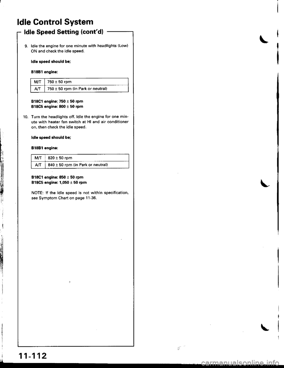
ldle Control System
ldle Speed Setting (cont'dl
ldle the engine for one minute with headlights (Low)
ON and check the idle speed.
ldle 3peed should b€;
B1881 engine:
MIT750 t 50 rpm
750 i 50 rDm (in Park or neutrall
818C1 engine: 7501 50 nm
818C5 engine: 8001 50 rpm
Turn the headlights off. ldle the engine for one min-
ute with heater fan switch at Hl and air conditioner
on, then check the idle speed.
ldl. spood should be;
Bl8Bl ongin.:
M/T820 i 50 rpm
lvT840 t 50 rpm (in Park or neutral)
818C1 €ngino: 850 i 50 rpm
818C5 engino: 1,050 t 50 rpm
NOTE: lf the idle speed is not within specification.
see Symptom Chart on page 1!-36.
\
L
i
lIh:
lffiiltfl!
ffi
| 11-112
\
I
Page 336 of 1680
In
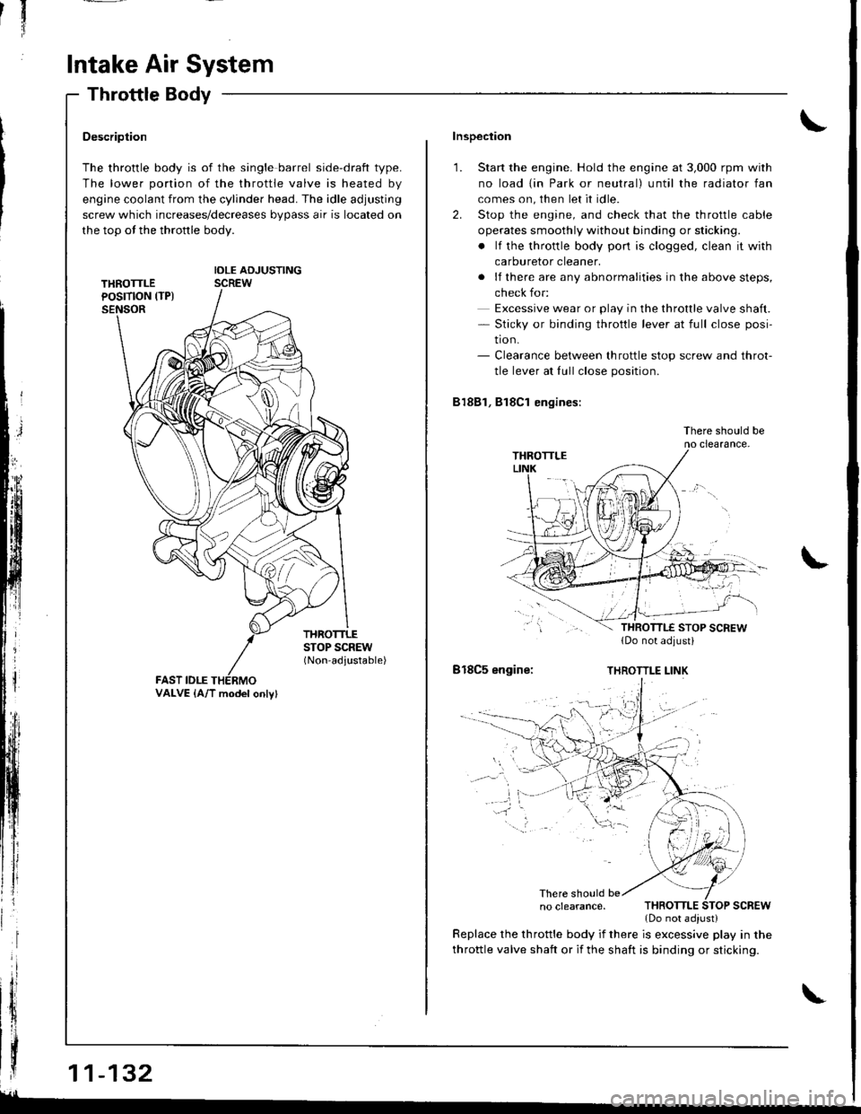
Intake Air System
Throttle Body
$;
Description
The throttle body is of the single barrel side-draft type.
The lower portion of the throttle valve is heated by
engine coolant from the cylinder head. The idle adjusting
screw which increases/decreases bypass air is located on
the top ot the thronle body.
IDLE ADJUSTINGSCREW
THROTTLESTOP SCREW(Non-adjustable)
FAST IDLE
| | .o clearance. THRoTTLE SToP scREw
{ | | _ .lDonotadiust)
| | y:::::::T,"9":::.'"Tl::f ,::i1::"1" fllyll-'n"
VALVE {A/T model onlv}
Inspection
1. Start the engine. Hold the engine at 3,000 rpm with
no load {in Park or neutral) until the radiator fan
comes on, then let it idle.
2. Stop the engine, and check that the throttle cable
operates smoothly without binding or sticking.
. lf the throttle body pon is clogged, clean it with
carburetor cleaner.
. lf there are any abnormalities in the above steps,
check for:
Excessive wear or play in the throttle valve shaft.- Sticky or binding throttle lever at full close posi-
tion.- Clearance between throttle stop screw and throt-
tle lever at fullclose position.
81881, Bl8Cl engines:
There should beno clearance.
818C5 engine:THROTTLE LINK
There should be
throttle valve shaft or if the shaft is binding or sticking.
glL-