frame ACURA INTEGRA 1998 Service Repair Manual
[x] Cancel search | Manufacturer: ACURA, Model Year: 1998, Model line: INTEGRA, Model: ACURA INTEGRA 1998Pages: 1680, PDF Size: 53.14 MB
Page 236 of 1680

t-
il
Troubleshooting ".
Troubleshooting Proccdures
How To Begin Troubleshooting
When the Malfunction lndicator Lamp {MlL) has been reponed on, or there is a driveability problem, use the appropri-
ate procedure below to diagnose and repair the problem.
A. When the MIL has come on:
'1. Connect the Honda PGM Tester or an OBD ll
scan tool to the 16P Data Link Connector (DLC)
located behind the front console right side.
2. Turn the ignition switch ON (ll).
3. Check the DTC and note it. Also check and note
the freeze frame data. Refer to the Diagnostic
Trouble Code Chart and begin troubleshooting.
NOTE:
. SeetheOBDll scantool or Honda PGM Tester user's manuals for specific operating instructions.
. The scan tool or tester can read the Diagnostic Trouble Codes (OTC). freeze frame data, current data, and other
Engine Control Module (ECM) data.
. Freeze frame data indicates the engine conditions when the first malfunction, misfire or luel trim malfunction
was detected. lt can be useful information when troubleshooting.
B. When the MIL has not come on, but there is a driveability problem, refer to the Symptom Chart on page 11-36.
C. DTCS wjll be indicated by the blinking of the Malfunction lNdicator Lamp {MlL) with the SCS service connector con-
nected.
Connect the SCS service connector to Service Check Connector as shown. (The 2P Service Check Connector is
located under the dash on the passenger's side of the car,) Turn the ignition switch on (lll.
scs sERvlcE coNNEcToEo?PAZ - 0010100
MAI-FUNCTIONINDICATORLAMP{MIL)
DATA LINK CONNECTOR Il6PI
OBO ll SCAN TOOL orHONDA PGM TESTER
Page 662 of 1680
I
Troubleshooting
17-14
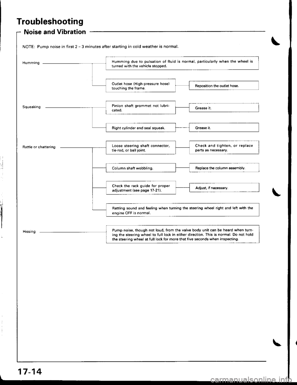
Noise and Vibration
NOTEr Pump noise in first 2 - 3 minutes after starting in cold weather is normal.
Humming
Rattle or chattering
Humming due to pulsation oI lluid is normal, particularly when the wheel isturned with the vehicle stoooed.
Outlet hose (High-pressure hose)touching the frame.
Right cylinder end seal squeak.
Pump noise, though not loud, from tho valv6 body unit can be heard when turn-ing the steering wheel to full lock in either direction. This is normal. Do not hold
the steering wh6el at tull lock tor more that live seconds wh€n inspecting.
Loose steering shaft connector,tie-rod, or ball ioint.
Check and tighten, or replacepans as necessary,
Column shaft wobbling.Reolace the column assemblv.
Check ihe rack guide tor proper
adjustment (see page 17-21).Adiust, if nec€ssary.
Rattling sound and feeling when turning the steering wheel right and left with the
engine OFF is normal.
Page 664 of 1680
Troubleshooting
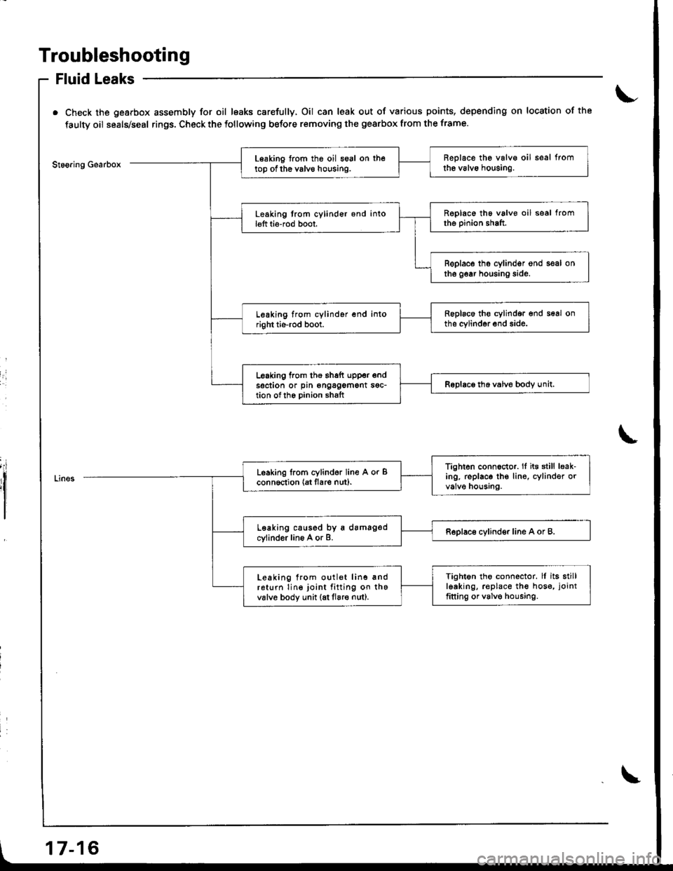
Fluid Leaks
Check the gearbox assembly for oil leaks carefully, Oil can leak out of various points, depending on location of the
faulty oil seals/seal rings. Check the following before removing the gearbox from the frame.
Stoo.ing GearboxReplace the valv€ oil seal fromthe valvo houging.Leaking from the oil seal on thetop of the valve housing.
Roplace the valve oil seal fromthe pinion shaft.Leaking trom cylinder 6nd intol€ft ti6-rod boot,
B€place tho cylindgr ond seal onthe gear housing side.
Replaco th€ cylindor end seal onths cylinder end side.Leaking from cylinder end intoright tie-rod boot.
Leaking from the thaft upper endsection or pin ongagement sgc-tion ofth6 Dinion shaftRoDlace tho valve bodv unit.I
I
Tighten connector. lf it€ still leak-ing. replace th€ lin€, cylinder orvalve housing.
Leaking lrom cylind6r line A or Bconn6ction {Et flare nut).
Leaking caused by a damagedcylinder line A or B.Replace cylinder line A or B.
Tightgn tho connector. ll its stillleaking, r€place the hos€, joint
fitting or valv€ housing.
Leaking from outlet line andreturn line joint fitting on thevalv6 body unit (at flare nut).
17-16
Page 670 of 1680
Inspection and Adjustment
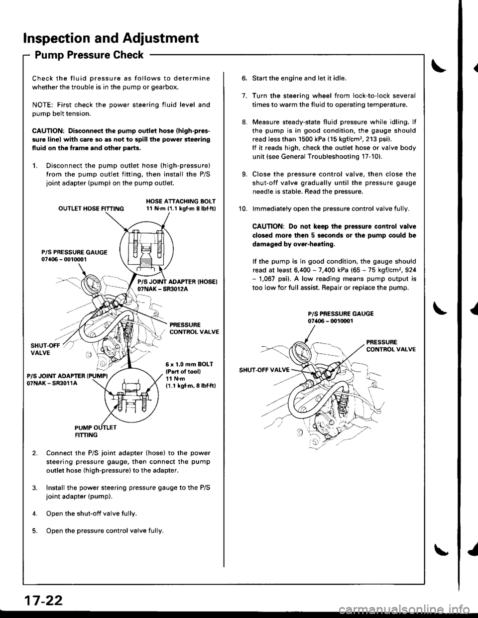
Pump Pressure Check
Check the fluid Dressure as follows to determine
whether the trouble is in the pump or gearbox.
NOTE; First check the power steering fluid level and
pump belt tension.
CAUTION: Disconnect the pump outlet hose (high-pres-
sure line) with care so as not to spill the power steering
fluid on the frame and other parts,
1. Disconnect the pump outlet hose (high-pressure)
from the pump outlet fitting, then install the P/S
joint adapter (pump) on the pump outlet.
P/S PRESSURE GAUGE07a06 - 001mo1
OUTLET HOSE FITTINGHOSE ATTACHING BOLT11 N.m (1.1 kgt.m 8lbl.ft)
PRESSURECONTROL VALVE
P/SAOAPTER IHOSEI07NAK - SR30124
6 x 1,0 mm BOLT
lP.n ol tooll'| 1 N.m
11.1 kgi.m,8lbtftl
PUMPFITTING
Connect the P/S joint adapter (hose) to the power
steering pressure gauge, then connect the pump
outlet hose (high-pressure)to the adapter.
Install the power steering pressure gauge to the P/S
joint adapter (pump).
Open the shut-off valve fully.
Open the pressure control valve fulli.
1.
Start the engine and let it idle.
Turn the steering wheel from lock-to-lock several
times to warm the fluid to operating temperature.
Measure steady-state fluid pressure while idling. lf
the pump is in good condition, the gauge should
read less than 1500 kPa (15 kgflcm'�,213 psi).
lf it reads high, check the outlet hose or valve body
unit (see General Troubleshooting 17-101.
Close the pressure control valve, then close the
shut-off valve gradually until the pressure gauge
needle is stable, Read the pressure.
lmmediately open the pressure control valve fully.
CAUTION: Do not keep the pressure control valve
closed more then 5 seconds or the pump could be
damaged by over-heating.
lf the pump is in good condition, the gauge should
read at least 6,400 - 7,400 kPa (65 - 75 kgflcm',924- 1,067 psi). A low.eading means pump output is
too low for full assist. Repair or replace the pump.
P/S PRESSURE GAUGE07i.{)6 - (x)l(xrol
9.
10.
SHUT.OFF VAI.VE
17 -22
{
I
Page 734 of 1680
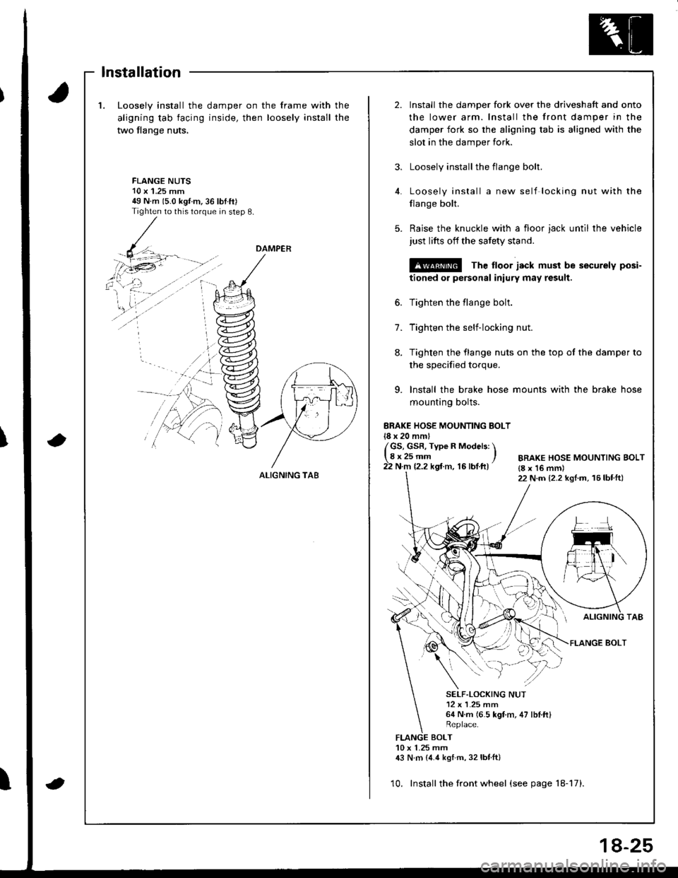
1.Loosely install the
aligning tab facing
two flange nuts,
damper on the frame with
inside, then loosely install
the
the
2.Install the damper fork over the driveshaft and onto
the lower arm. Install the front damper in the
damper fork so the aligning tab is aligned with the
slot in the damper fork.
Loosely install the flange bolt.
Loosely install a new self locking nut with the
flange bolt.
Raise the knuckle with a floor jack until the vehicle
just lifts off the safety stand.
@ The ltoor jack must be securely posi-
tioned or personal iniury may result.
Tighten the flange bolt.
Tighten the self-locking nut.
Tighten the flange nuts on the top of the damper to
3.
FLANGE NUTS10 x'1.25 mm49 N m 15.0 kgt m,36 lbtft)Tighten to this torque in step 8.
4.
5.
6.
7.
8.
the specified torque.
9. lnstall the brake hose mounts with the brake hose
mounting bolts.
ERAKE HOSE MOUNTING BOLT18 x 20 mml
/GS, GsR, Type R Models: \lgr25-- ,22 N.m 12.2 kgt m, 16 lbf.ft)BRAKE HOSE MOUNTING BOLT{8 x 16 mm)22 N.m {2.2 kgl.m, 16lbtft}
FLANGE BOLT
SELF.LOCKING NUT12 x L25 mm64 N.m (6.5 kgt m, 47 lbI.ftl
BOLT10 x 1.25 mm,|:} N.m {4.4 kstm, 32lbtft}
10. Install the front wheel (see page 18-17).
DAMPER
ALIGNING TA8
lnstallation
8-25
Page 815 of 1680
!
Body
Bumpers
Front Bumper Replacement ....................-..... 20-111
Rear Bumpar Replacemeni
Hatchback ................. 20-1/B
Sedan .................... ....20-111'Carpet
. Repfacemenl .,.,.,.,,..-....-.20-126
Consoles, Front and Rear
* Replacement ..................20-130
Dashboard
Component Removal/lnstallation ................ 20-133
Replacement Precautions ...........,................. 20-138
R€placement ....,.,...........20-139
Doors
Door Index Hatchback ................................... 20-2
Front Door Index Sedan .................,.,..,.,....,.. 20-18
Rear Door Index Sedan ........,.,........,.............. 20-30
Emblems
Installation .....................20-167
FenderwellTrim
+ Replacement., ................20.162
Fram€ Repair Chart .-..........20-170
Hatch
Replacoment .......,..........20-118
Adiustment .................... 20-150
Hatch Latch and Lock Cylinder
Replacement ..,.,..... ........ 20-158
Hstch Spoiler
Replacement ......... .......-.20.161
Hatch Weatherstrip/Trunk Lid Wsatherstrip
Replacement ..................20.163
Headliner
ReDlacement
Hatchbsck ,.,....,......,.. 20-98
Sedan .........................................................20-100
Hood
Replacsment ......... ......... 20.146
Adiustment ....................20-117
lnterior Trim
Reolacement
Hatchback ................. 20-91
Sedan .........................................................20-9,1
Mirrors
Power Mirror Reolacement ..........,................ 20-49
Mirrol Holder Removal ............................,..... 20.50
Mirror Holder Installation .............................. 20-50
Mirror Visor and Mirrot Covet
Replacement
Haichback ............20-51
Sedan .................................................... 20-51
Rearview Mirror Reolacement ..........-....-.-.... 20.52
Roof Molding Rep|acament ................................ 20.164
Door and Sid€ Moldings
Replacement .,..........,..... 20-165
Moonroot
lnd6x
Hatchback -................20-77
Sodan .........................................................20-8il
Opener and Latch
Replacement .......... ......,. 20-156
Opensr Cables
Replacamsnt .,.,...,.. ......., 20-154
Retainers and W€atherstrip
Replacement .................. 20-160
Seats
Front Seat Romoval ....................................... 20-103
Front Seat Replacement ...........................,.,.. 20-104
Front Soat Disassembly and Reassembly ...20-106
Torsion Bar ReDlacomant .....,...,......,.......,..,., 2O-1O7
Seat Eelt Switch Ha.ness Location ..,...,.,.,..,2O-1O7
Front Seat Cover Replacemont ..,....,..,..,.....,. 20-108
Rear Soat Roplscemont
Hatchback ................. 20.110
Sedan.........................................................20-112
R€al Seat Cover Replacomont ...................... 20-114
Seat Belts
Front Seat Beh Replacement
Hatchback..................20.117
Sedan20-r18
Rear S6at Bolt R€plac€ment
Hatchback .-......-.-......20-121
Sedan.......................-.-....-.-..........-.............20-122
fnspection ......-.-.,....-.-....20-121
Chifd Seat Anchor Plate ................................ 20-125
Side Sill Panol
Beplacom€nt .................. 20-166
Sub-frame ........................... 20.169
Trunk Lid
Replacement ......... ..,..,.,.20-151
Adiustmeni .................... 20-153
Trunk Lid Latch and Lock Cvlindot
Replac€ment ......... ......... 20-159
Trunk Trim
Replacement .,.,,.,........... 20-97
Windshield, Rear Window, Ouarter Glass
lndex
Hatchback ...........,,.20-53
!
S6dan ......................................................... 20.54
Page 891 of 1680
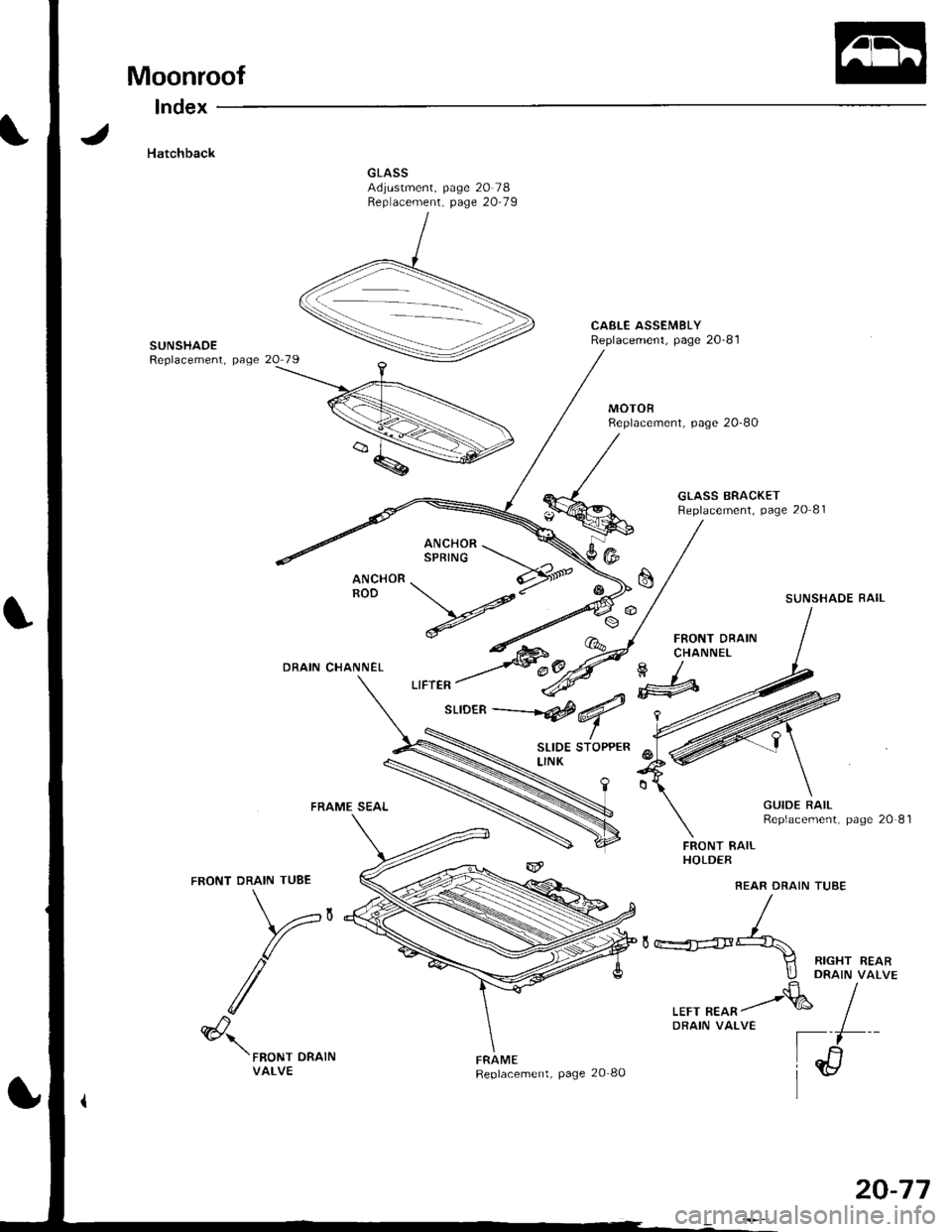
Moonroof
lndex
Hatchback
CAELE ASSEMBLYReplacement, page 20-81SUNSHAOEReplacement, page
MOTOBReplacement, page 20-80
GLASS BRACKETReplacement, page 20 81
SUNSHADE RAIL
FRONT DRAINCHANNELDRAIN CHANNEL
FRAME SEAL
FRONT DRAIN TUBE
V,
/
SLIDE STOPPERLINK
FRAMEReplacement, page 20 80
FRONT RAILHOLDER
REAR DRAIN TUSE
GUIDE RAILReplacement, page 20 81
(@
II RIGHT REARllj DRA|N vaLVE.fr/
,rr, ^*^/& IDRAIN VALVE I
[il
ir/l
@'\'FRoNT DRATNVALVE
20-77
Page 892 of 1680
Moonroof
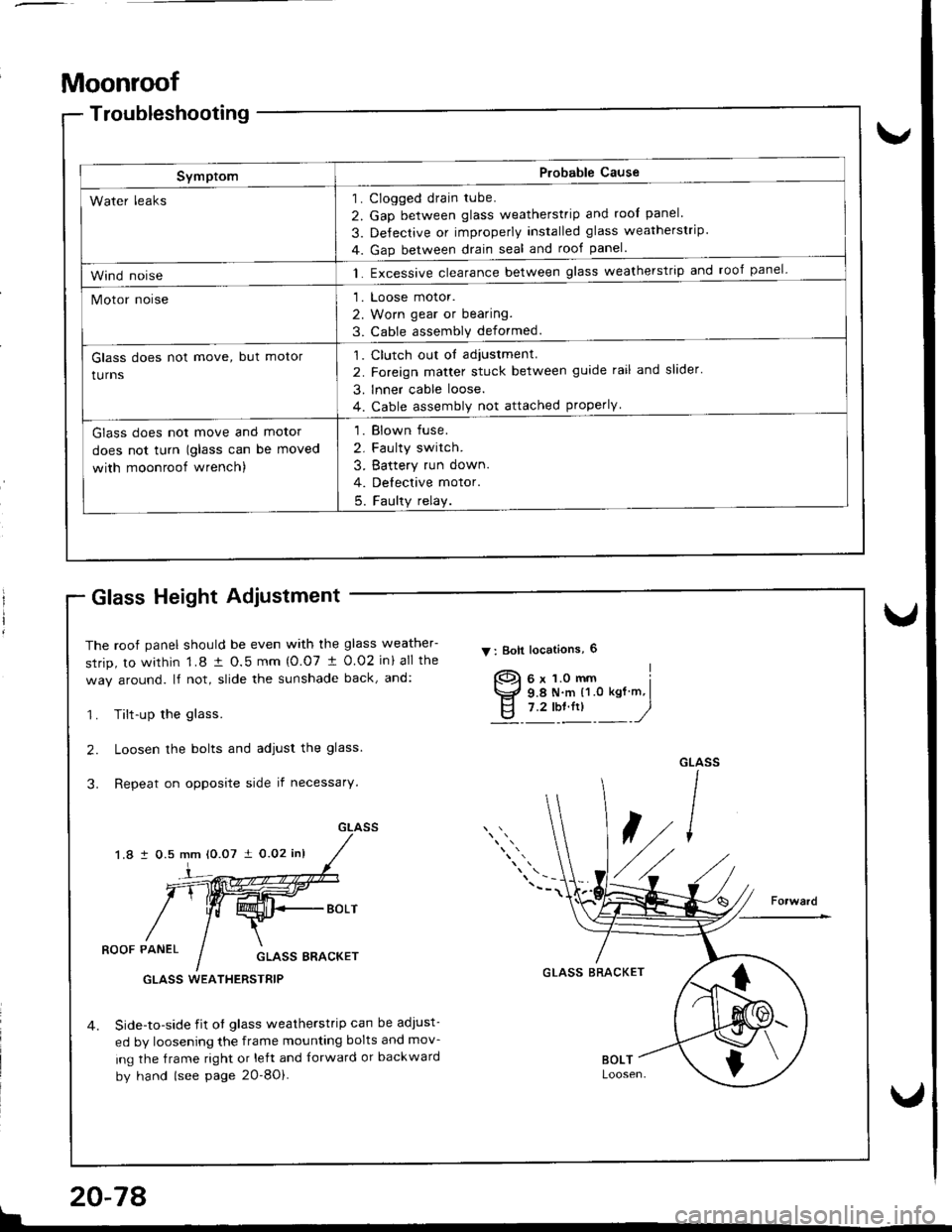
Troubleshooting
SymptomP.obable Cause
Clogged drain tube.
Gap between glass weatherstrip and roof panel
De{ectrve or improperly Installed glass weatherstrip
Gap between drain seal and rool panel.
Excessive clearance between glass weatherstrip and roof panel-
Loose motor.
Worn gear or bearing.
Cable assemblv deformed.
1
2
3
4
1
2
3
1.
Water leaks
Wind noise
Motor noise
Glass does not move, but motor
turns
Clutch out ol adiustment.
Foreign matter stuck between guide rail and slider'
lnner cable loose.
Cable assembly not attached properly
,l
2
3
4
Glass does not move and motor
does not turn (glass can be moved
with moonroof wrench)
1. Blown fuse.
2. Faulty switch.
3. Battery run down.
4. Delective motor.
5. Faulty relay.
Glass Height Adiustment
The roof panel should be even with the glass weather-
srrip, to within 1.8 t O.5 mm {O.07 t 0.02 in} all the
way around. lf not, slide the sunshade back, and:
1. Tilt-up the glass.
2. Loosen the bolts and adjust the glass.
3. Repeat on opposite side if necessary.
1.8 i 0.5 mm 10.07 i 0.02 inl
V : Boll locations, 6
]-
ROOF PANELGLASS BRACKET
Side-to-side iit of glass weatherstrip can be adJust-
ed by loosening the frame mounting bolts and mov-
ing the frame right or left and {orward or backward
by hand (see page 2O-8Oi.
GLASS BRACKETGLASS WEATHERSTRIP
{
$
I
!
20-78
Page 894 of 1680
Moonroof
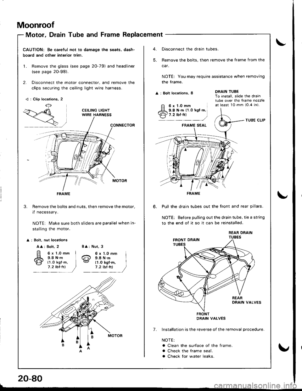
Motor, Drain Tube and Frame Replacement
CAUTION: Be careful not to damage the seats, dash-
boa.d and other interior trim.
1. Remove the glass (see page 20-79) and headliner
{see page 2O-98}.
2. Disconnect the motor connector, and remove the
clips securing the ceiling light wire harness.
Remove the bolts and nuts, then remove the motor,
if necessary.
NOTE: Make sure both sliders are parallel when in-
stalling the motor.
3.
: Bolt, nut locations
A
: 8olt, 2
6x 1.0mm I9.8Nm L
Nut, 3
6 x 1.0 mm I9.4 N.m
BA:
6@{1.0 kgf7 .2 tbl:!)(1.O kgf m, I
1'�lIltl /
< : Clip locations, 2
4,
FRAME
Oisconnect the drain tubes.
Remove the bolts, then remove the lrame from the
car.
NOTE: You may require assistance when removing
the trame.
A : Bolt locations, 8
TUBE CLIP
FRAME SEAL
Pull the drain tubes out the front and rear pillars.
NOTE: Before pulling out the drain tube, tie a string
to the end of it so it can be reinstalled.
REAR DRAINTUBES
7. Installation is lhe reverse of the removal procedure.
NOTE:
a Clean the surtace of the frame.
a Check the lrame seal.
a Check tor water leaks.
DRAIN TUBETo install, slide the draintube over the {rame nozzleat least 10 mm i0.4 in).
-'
6 x 1.0 mm9.8 N.m 11.0 kgt m,7.2 tbf.fr)
FRAME
FRONTDRAIN VALVES
!
\"
20-80
\
v
Page 895 of 1680
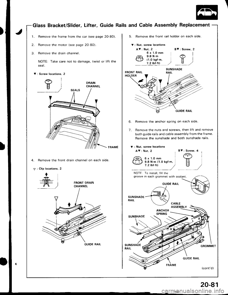
Glass Bracket/SlidetLifterGuide Rails and Cable Assembly Replacement
1.
2.
3.
Remove the frame from the car (see page 20 8O).
Remove the motor (see page 20 80).
Remove the drain channel.
NOTE: Take care not to damage, twist or lift the
sea L
5. Remove the front rail holder on each side.
V: Nut, scaew locations
AV: Nut, 2Bv: Screw, 2
1er I
YIc,/
6 x 1.0 mm9.8Nm('1.0 kgf m, I7 2 !!!!!l ./
V : Screw locations. 2
/e, I
Y)
6.
7.
Remove the anchor spring on each side.
Remove the nuts and screws, then lift and remove
both guide rails and cable assembly from the frame.
Remove the sunshade and both sunshade rails.
FRAMEV : Nut, screw locations
AV: Nut, 2Bv: Screw, 4
4. Remove the tront drain channel on each side.
V : Clip locations, 2
I
@
NOTE: To install, Iill rhegroove in each grommet with sealant.
FRONT DBAINCHANNELGUIDE RAIL
,._--'//r\/-rr / \
sur'rsHaor ---i:579 )RA|L \/\---_ _/,/ CABLE
ANCHORSPFING
GUIOE RAIL
GUIDE RAIL
GROMMET