oil pan ACURA INTEGRA 1998 Service Repair Manual
[x] Cancel search | Manufacturer: ACURA, Model Year: 1998, Model line: INTEGRA, Model: ACURA INTEGRA 1998Pages: 1680, PDF Size: 53.14 MB
Page 146 of 1680
I
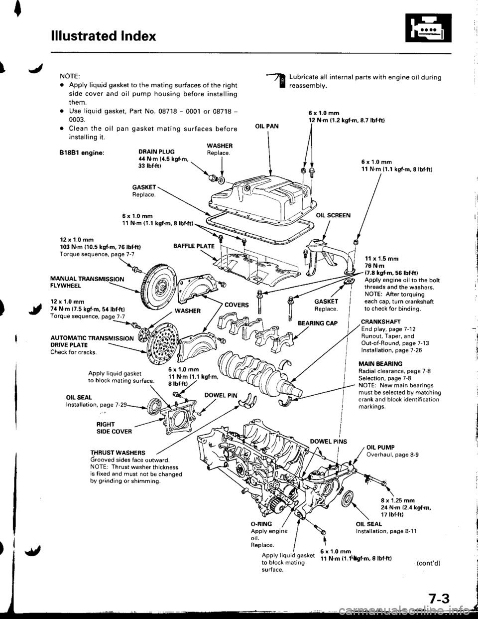
lllustrated Index
INOTE:
. Apply liqujd gasket to the mating surfaces ot the right
side cover and oil pump housing before installing
them.
. Use liquid gasket,
0003.
. Clea n the oil pan
installing it.
B18Bl engine:
Part No. 087'18 - 0001 or 08718 -
gasket mating surfaces before
Lubricate all internal parts with engine oil during
reassemDly.
6x1.0mm12 N.m {1.2 kg{.m,8.7 lbt.ft}
6x1.0mm11 N.m 11.1 kg'f.m,8 lbt.ftl
OIL SCREEN
DEAIN PLUG4il N.m 14.5 kgt m,33 tbtft)
BAFFLE PLATE
6x1.0mm1'l N.m (1.1 kgt.m,8 rbr.ftl
OIL PAN
O.FING
CAP
DOWEL PINS
WASHERReplace.
GASKETReplace.
6x1.0mm11 N.m (1.1 kgl.m, 8 lbl.ft)
12 x 1.0 mm103 Nm 110.5ks{.m,76lbf.ft}
MANUAL TRANSMISSIONFLYWHEEL
12 x 1.0 mm74 N.m 17.5 kgf.m,54lbf.tr)Torque sequence, page 7-7
AUTOMATIC TRANSMISSION
WASHERcovERsGASKETReplace.
11 x 1.5 mm76 N.m17.8 kgt m, 56 lbtft)Apply engine oilto the boltthreads and the washers.NOTE: After torquingeach cap, turn crankshaftto check for binding.
ORIVE PLATECheck for cracks.
Apply liquid gasketto block mating surface.
CRANKSHAFTEnd play, page 7-12Runout, Taper, andOut-of'Round, page 7-13Installation, page 7-26
MAIN AEARINGRadialclearance, page 7 8Selection, page 7'8NOTE: New main bearingsmust be selected by matchingcrank and block identificationmarkrngs.
I
i
OIL SEALlnstallation, page 7
RIGHTSIDE COVER
THRUST WASHERSGrooved sides face outward.NOTE: Thrust washer thicknessis fixed and must not be changedby grinding or shamming.
8 x 1.25 mm21 N..n l2.1kga'r,�,17 tbf.ft)
OIL SEALInstallation, page 8-1 1Apply engineorl.Replace.
Apply liquid gasket
to block matingsurface,
6x1.0mm11 N.m t1.lilh{.m,I lbf.ft}(cont'd)
Page 153 of 1680
Connecting Rod BearingsCrankshaft
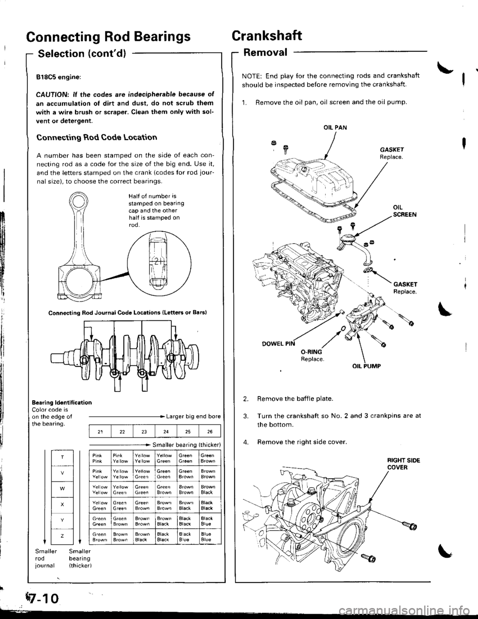
Selection (cont'dlRemoval
818C5 engine:
CAUTION: lf the codes are indecipherable because of
an accumulation of dirt and dust, do not scrub them
with a wire brush or scraper. Clean them only with sol-
vent or detergent.
Connecting Rod Code Location
A number has been stamped on the side of each con-
necting rod as a code for the size of the big end. Use it,
and the letters stamped on the crank lcodes for rod jour-
nal size), to choose the correct bearings.
ilb
Color code ison the edge ofthe bearing.Larger big end bore
Smaller bearing (thicker)
Smallerbeal|ng(thicked
1rI
llli
tl
ilI
I
*z-t o
Smallerrodjournal
Connecting Rod Journal Code Locations {Letters or Barsl
Beering ldentitication
NOTE: End play for the connecting rods and crankshaft
should be inspected before removing the crankshaft.
1. Remove the oil pan, oil screen and the oil pump.
GASKETReplace.
Remove the baffle plate.
Turn the crankshaft so No.2 and 3 crankpins are at
the bottom.
Remove the right side cover.
OIL PAN
Half of number isstamped on bearingcap and the otherhalf is stamped onrod.
212223242526
T
z
Black
Black
Blue
Page 160 of 1680
t
Installation
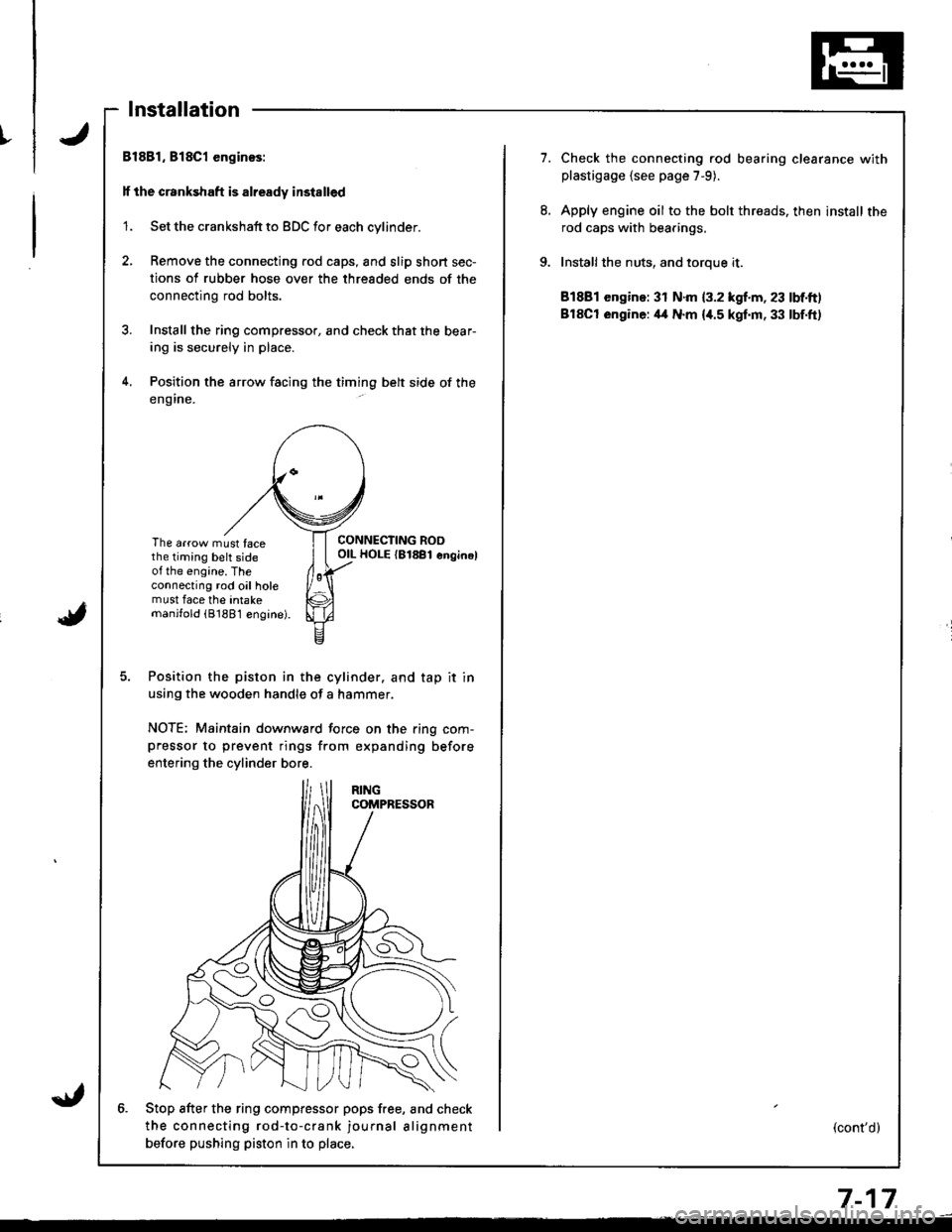
Bl881, 818C1 enginos:
lf the crankshaft is already installed
'1. Set the crankshaft to BDC for each cylinder.
2, Remove the connecting rod caps, and slip short sec-
tions of rubber hose over the threaded ends of the
connecting rod bolts.
3. Install the ring compressor, and check that the bear-
ing is securely in place.
4. Position the arrow facing the timing belt side of the
eng ine.
The arrow must facethe timing belt sideot the engine. Theconnecting rod oil holemust face the intakemanjfold (81881 engine).
CONNECTING ROOOIL HOLE {81881 enginel
Position the piston in the cylinder. and tap it in
using the wooden handle of a hammer.
NOTE; Maintain downward force on the ring com-pressor to prevent rings from expanding before
entering the cylinder bore.
6. Stop after the ring compfessor pops free, and check
the connecting rod-to-crank journal alignment
betore pushing piston in to place,
7.Check the connecting rod bearing clearance withplastigage {see page 7-9).
Apply engine oil to the bolt threads. then install the
rod caps with bearings,
Installthe nuts, and toroue it.
81881 engine: 31 N.m {3.2 kgf.m, 23 lbf.ft)
BlSCt engine: il4 N.m {i[.5 kgf.m, 33 lbf.ft)
(cont'd)
7-17
Page 161 of 1680
I
i
Pistons
Installation (cont'dl
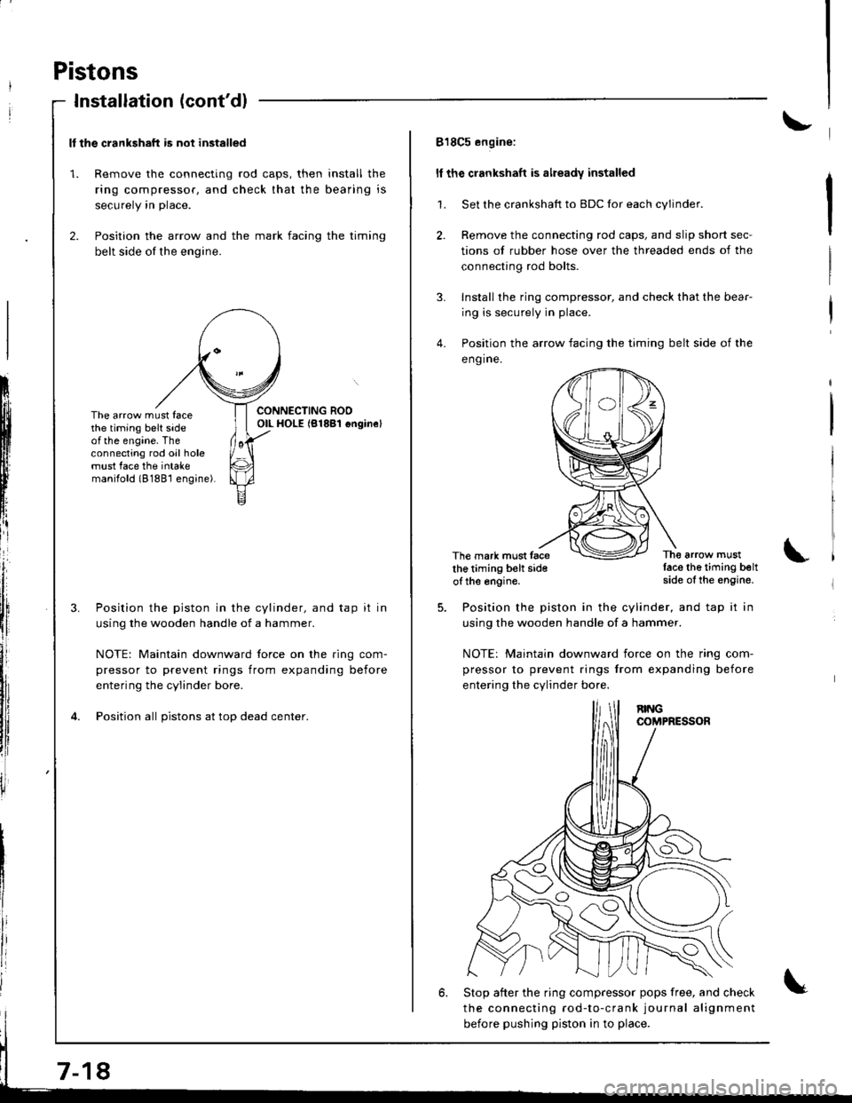
ll the crankshaft is not installed
1. Remove the connecting rod caps, then install the
ring compressor. and check that the bearing is
securely in place.
2. Position the arrow and the mark facing the timing
belt side of the engine.
ItIl
Iti
tfll|lflI[lrB
[:
i"lrt
i'
ff
ll,
illi
llillr
il
The arrow must facethe timing belt sideof the engine. Theconnecting rod oil holemust face the intakemanilold (8188'l engine).
Position the piston in the cylinder, and tap it in
using the wooden handle of a hammer.
NOTE: Maintain downward force on the ring com-
pressor to prevent rings from expanding before
entering the cylinder bore.
Position all pistons at top dead center.
7-18
818C5 engine:
ll the crankshaft is already installed
1. Set the crankshaft to BDC for each cylinder.
2. Remove the connecting rod caps, and slip short sec-
tions of rubber hose over the threaded ends of the
connecting rod bolts.
3. Install the ring compressor, and check that the bear-
ing is securely in place.
4. Position the arrow facing the timing belt side of the
eng ine.
The mark must facethe timing belt sideof the engine.
The arrow mustlace the timing beltside of the engine.
Position the piston in the cylinder, and tap it in
using the wooden handle of a hammer.
NOTE: Maintain downward iorce on the ring com-
pressor to prevent rings from expanding before
entering the cylinder bo.e.
6. Stop after the ring compressor pops free, and check
the connecting rod-to-crank journal alignment
before pushing piston in to place.
Page 162 of 1680
I
7.
8.
9.
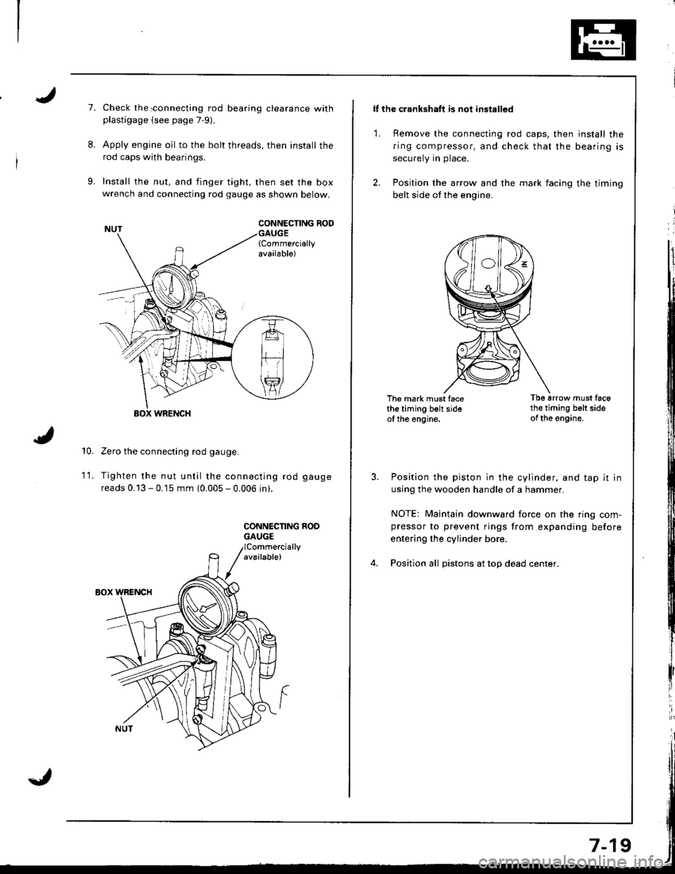
Check the sonnecting rod bearing clearance withplastigage (see page 7-9).
Apply engine oil to the bolt threads, then install the
rod caps with bearings.
Install the nut, and finger tight, then set the boxwrench and connecting rod gauge as shown below.
CONNCCNNG RODGAUGE{Commerciallyavailable)
10.
WRENCH
Zero the connecting rod gauge.
Tighten the nut until the connecting rod gauge
reads 0.13 - 0.15 mm (0.005 - 0.006 in).
CONNECNNG HOOGAUGE
1t.
ll the crankshaft is not installed
1. Remove the connecting rod caps, then install the
ring compressor, and check that the bearing is
securely in place.
2. Position the arrow and the mark facing the timing
belt side ot the engine.
The mark must facethe timing belt sideof the engine.
Tb6 arrow must tac6th€ timing belt sideof the engine.
Position the piston in the cylinder, and tap it in
using the wooden handle of a hammer.
NOTE: Maintain downward force on the ring com-pressor to prevent rings from expanding before
entering the cylinder bore.
Position all pistons at top dead center.
Page 163 of 1680
Piston Rings
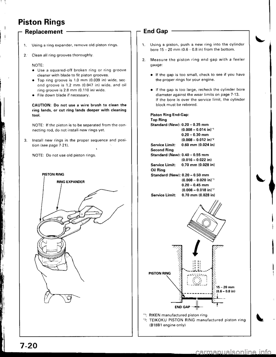
Replacement
Using a ring expander, remove old piston rlngs.
Clean all ring grooves thoroughly.
o Use a squared-ofl broken ring or ring groove
cleaner with blade to fit piston grooves.
. lop ring groove is 1.0 mm (0.039 in) wide, sec
ond groove is 1.2 mm (0.047 in) wide, and oil
ring groove is 2.8 mm (0.110 in) wide.
. File down blade if necessary.
CAUTION: Do not use a wire brush to clean the
ring lands, or cut ring lands deeper with cleaning
tool.
NOTE: lf the piston is to be separated from the con
necting rod, do not install new rings yet.
Install new rings in the proper sequence and posa-
tion (see page 7 21).
Do not use old piston rings.
PISTON RING
End Gap
Using a piston, push a new ring into the cvlinder
bore 15 - 20 mm 10.6 0.8 in) f rom the bottom.
2. N,4easure the piston ring end gap with a feeler
gauge:
lf the gap is too small, check to see if you have
the proper rings for your engine.
. lf the gap is too large, recheck the cylinder bore
diameter against the wear limits on page 7-13.
lf the bore is over the service limit, the cylinder
block must be rebored.
Piston Ring End-Gap:
Top Ring
Standard (New):0.20 - 0.35 mm
(0.008 - 0.014 inl'1
0.20 - 0.30 mm
{0.008 - 0.012 in}''�
Service Limit: 0.60 mm {0.024 in)
Second Ring
Standard {New): 0.40 - 0.55 mm
{0.016 - 0.022 inl
Service Limit: 0.70 mm {0.028 inl
Oil Ring
Standard (New): 0.20 - 0.50 mm
10.008 - 0.020 in)'r
0.20 - 0.45 mm
(0.008 - 0.018 in)''�
Service Limit: 0.70 mm (0.028 in)
PISTON RING
15-20mm{0.6 - 0.8 in)
RIKEN manufactured piston ring
TEIKOKU PISTON RING manufactured piston ring
(B 1881 engine only)
Page 171 of 1680
Crankshaft
Installation (cont'd)
I
I
t
l;I
I
fi,
\
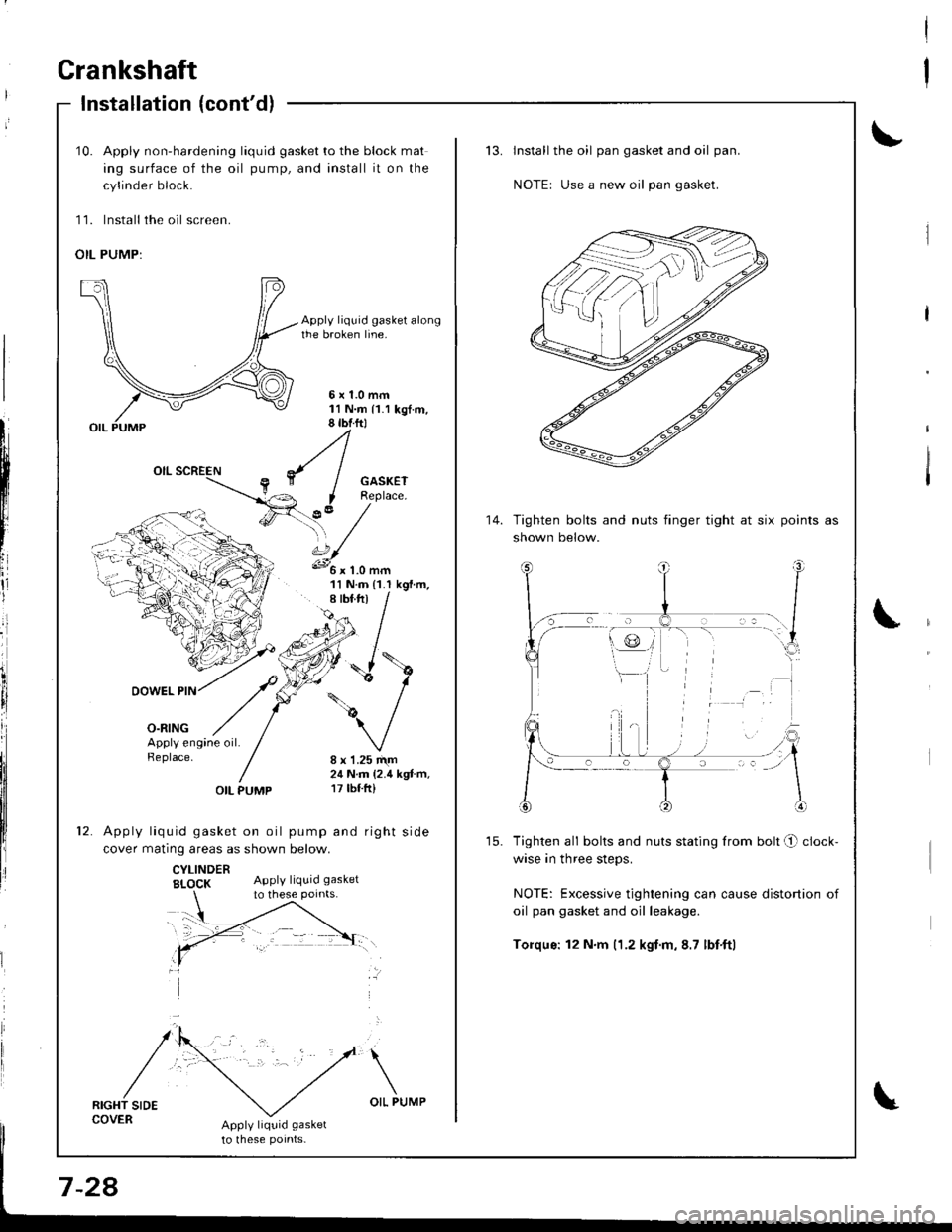
10. Apply non-hardening liquid gasket to the block mat
ing surface of the oil pump, and install it on the
cylinder block.
11. lnstall the oil screen.
OIL PUMP:
Apply liquid gasket alongthe broken line.
5x1.0mm11N.m 11.1 kgt.m,8 tbtftl
GASKETReplace.
?,' /'\, /s.../
11 N.m {1.I kgf.m,
DOWEL PIN
o-ntNG
/\
/
':'
Apply engine oil.Replace.8 x 1.25 r\m24 N.m (2.4 kgt.m,17 tbf.ft)OIL PUMP
Apply liquid gasket on oil pump and right side
cover matinq areas as shown below.
CYLINDERBI_OCK Apply liquid gasket
RIGHT SIDECOVERApply liquid gasket
to lhese potnts-
to these points.
Install the oil pan gasket and oil pan.
NOTEr Use a new oil pan gasket.
Tighten bolts and nuts finger tight at six
shown below.
points as
Tighten all bolts and nuts stating from bolt O clock-
wise in three steps.
NOTE: Excessive tightening can cause distortion of
oil pan gasket and oil leakage.
Torqus: 12 N.m (1.2 kgf.m,8.7 lbf'ftl
14.
Page 172 of 1680
Oil Seal
Installation
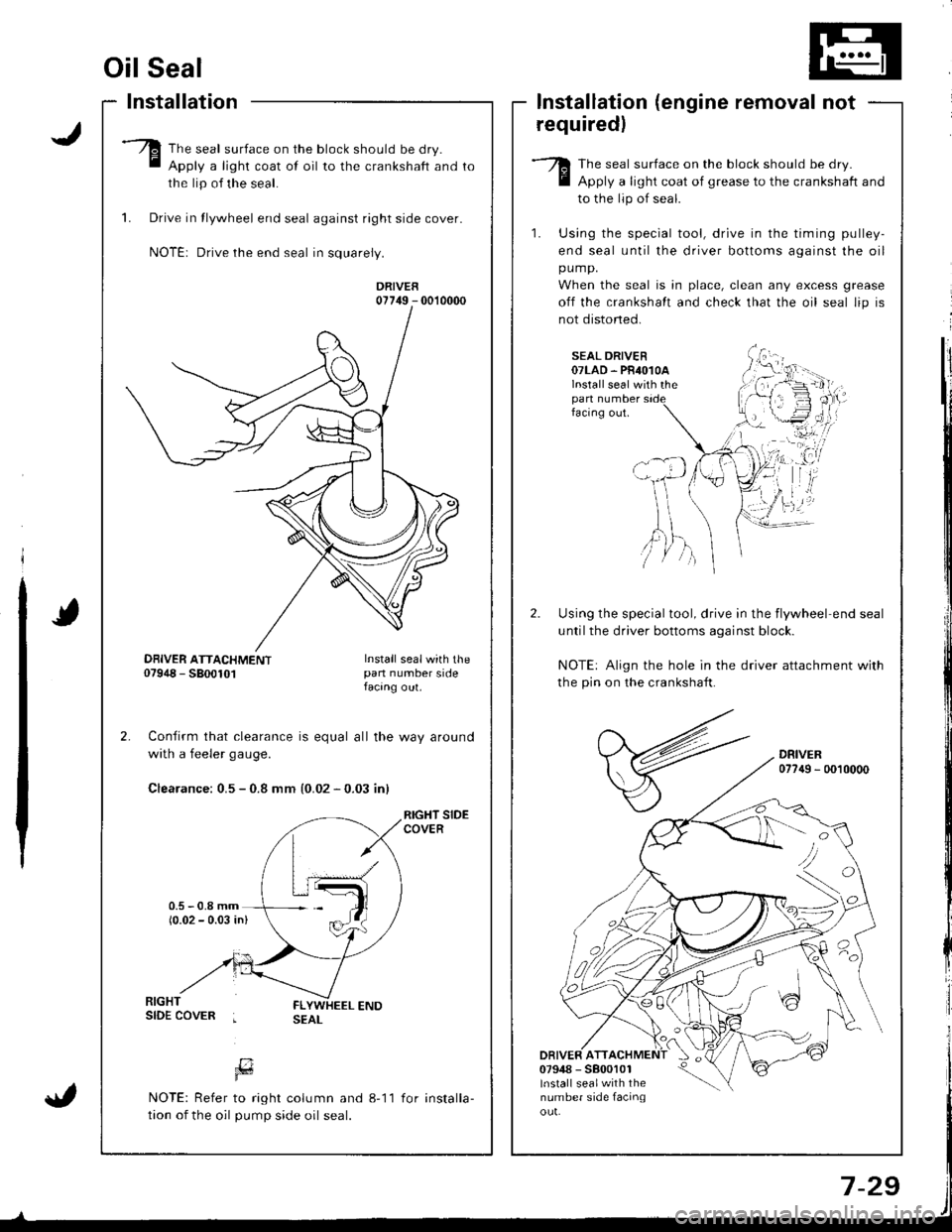
The seal surface on the block should be dry.
Apply a light coat of oil to the crankshaft and
the lip of the seal.
1. Drive in tlywheel end seal against right side cover.
NOTE: Drive the end seal in squarely.
DRIVER07749 - 0010000
Confirm that clearance is equal all the way around
with a feeler gaug€.
Clearance: 0.5 - 0.8 mm {0.02 - 0.03 inl
RIGHT SIDECOVER
lnstallation (engine removal not
requiredl
The seal surface on the block should be dry.
Apply a light coat of grease to the crankshaft and
to the lip of seal.
1. Using the special tool, drive in the timing pulley-
end seal until the driver bottoms against the oil
pump.
When the seal is in place, clean any excess grease
off the crankshalt and check that the oil seal lip is
not distoned.
SEAL DRIVER07LAD. PR4O1OAlnstall seal with thepan numberfacing out.
Using the special tool, drive in the flywheel end seal
untilthe driver bottoms aqainst block.
NOTE: Align the hole in the driver attachment with
the pin on the crankshaft.
DRIVER077{9 - 0010000
DRIVER ATT07948 - 5800101lnstall sealwith thenumber side facinqou!.
'tvA,)/ )
DBIVER ATTACHMENT07948 - 5800101Install sealwith thepan number sidefacang out.
[7Fd
NOTE: Refer to right column and 8-11
tion of the oil pump side oil seal.
for installa-
Page 175 of 1680
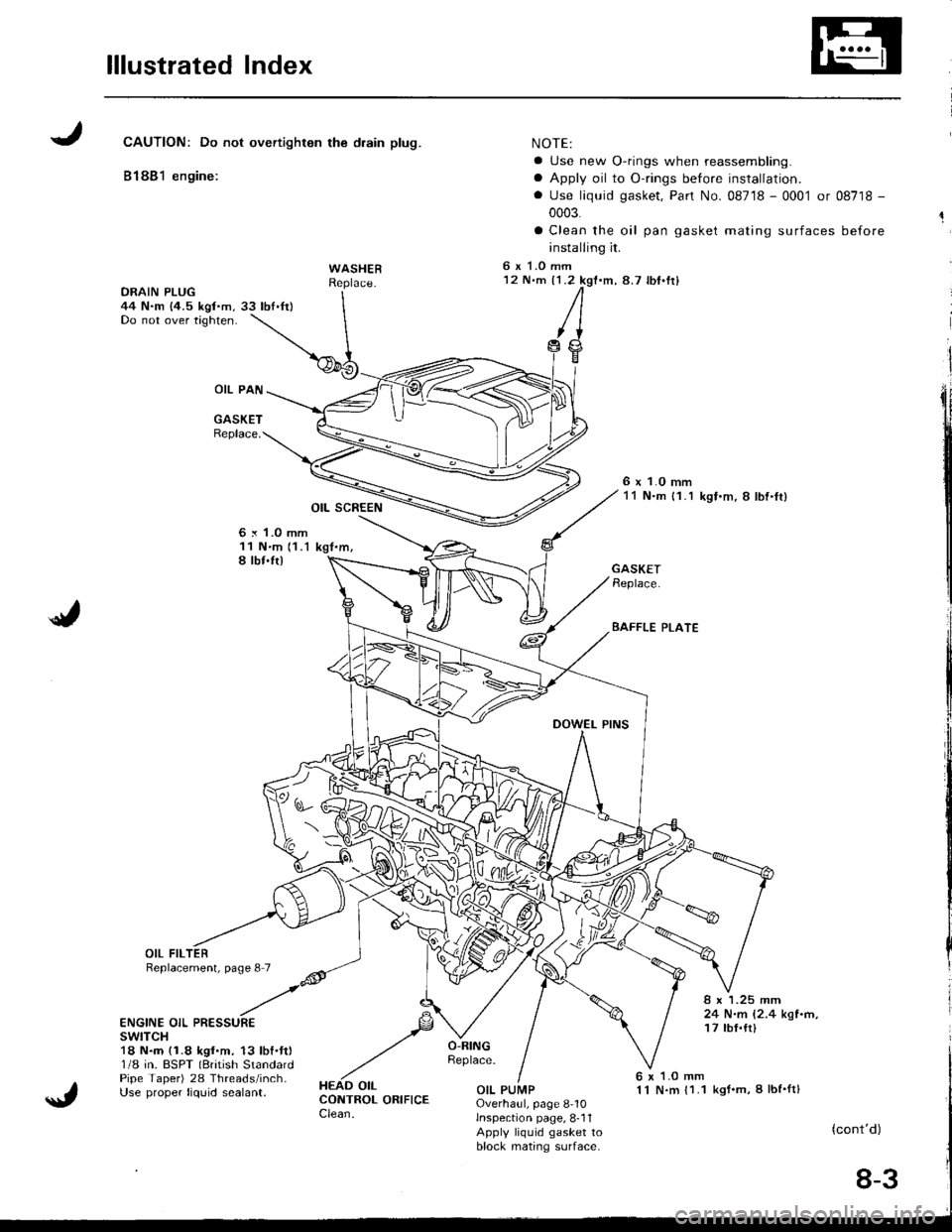
lllustrated Index
JCAUTION: Do not overtighton the drain plug.
81881 engine:
WASHER
OIL PAN
GASKETReplace.
OIL SCREEN
6 x 1.0 mm11 N'm 11.1 kgt.m,I lbt.ft)
NOTE:
a Use new O-rings when reassembling.
a Apply oil to O-rings before installation.
. Use liquid gasket, Pan No. 08718 - 0001 or 08718 -
0003.
a Clean the oil pan gasket mating surfaces before
installing it.
6 x 1.O mm12 N'm {1.2 kgf.m,8.7 lbf'fr)
/I
,trg
6 x 1.0 mm11 N.m {1.1 kgf.m, 8 lbl.ft}
./
GASKETReplace.
BAFFLE PLATE
8 x 1.25 mm24 N.m 12.4 kgl.n,17 tbf.tt)ENGINE OIL PRESSUREswtTcH18 N.m (1.8 kgf.m. 13 lbf.ft)1/8 in. BSPT (British StandardPipe Taper) 28 Threads/inch-Use proper liquid sealant.
6 x 1.O mm1 l N.m {1.1 kgt.m, I lbf'ft}OIL PUMPOverhaul, page 8-10lnspection page, 8-11Apply liquid gasket toblock mating s(]lrface-
(cont'd)
8-3
Page 176 of 1680
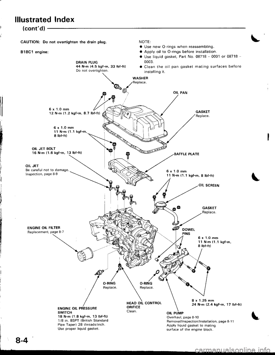
lllustrated Index
(cont'dl
CAUTION: Do not ovenighten the drain plug.
B18C1 engine:
NOTEI
a Use new O rings when reassembling.
a Apply oil to O rings before installation.
. Use liquid gasket, Part No. 08718 0001 or 08718 -
0003.
a Clean the oil pan gasket mating surfaces before
installing it.
WASHERReplace.
DRAIN PLUG44 N.m {4.5 kgf.m,33 lbf.ft)Do not overtighten.
tl
tl
6x LO mm12 N.m {1.2 kgf.m, 8.7 lb{.It}
6 x 1.o mm11 N.m (1.1 kgl.m,8 tbf.fi)
OIL JET BOLT16 N.m {1.6 kgt.m, 13 lbf'ft)
L
III
ij
i
OIL JETBe careful not to damage.lnspection, page 8-9
ENGINE OIL FILTERReplacement, Page 8'7
6 x 1.O mm1 1 N.m (1.1kgf.m,8lbf.Ir)
OIL SCREEN
DOWEL
GASKETReplace.
6x 1.O mm11 N.m {1.1a tbf.ft)k9f.m,
8 x 1.25 mm24 N.m {2.4 kqt'm, 17 lbf.ftlENGINE OIL PRESSUBEswrTcH18 N.m {1.8 kgf.m, 13 lbf.ftl1/8 in. ESPT (Brirish StandardPipe Taper) 28 threads/inch.Use proper liquid gasket.
Overhaul, page 8-10RemovaUlnspection'lnstallation. page 8 11Apply liquid gasket to matingsurtace of the engine block.
8-4