automatic transmission ACURA NSX 1991 Service Repair Manual
[x] Cancel search | Manufacturer: ACURA, Model Year: 1991, Model line: NSX, Model: ACURA NSX 1991Pages: 1640, PDF Size: 60.48 MB
Page 4 of 1640
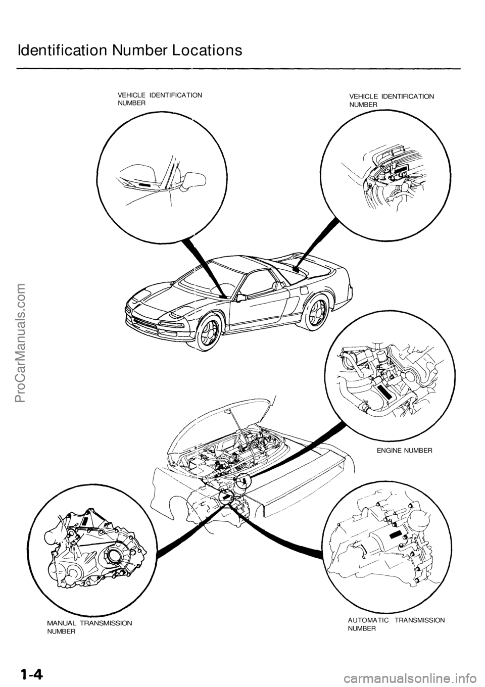
Identification Number Locations
VEHICLE IDENTIFICATION
NUMBER
VEHICLE IDENTIFICATION
NUMBER
MANUAL TRANSMISSION
NUMBER
AUTOMATIC TRANSMISSION
NUMBER
ENGINE NUMBERProCarManuals.com
Page 408 of 1640
System Description
Major Components
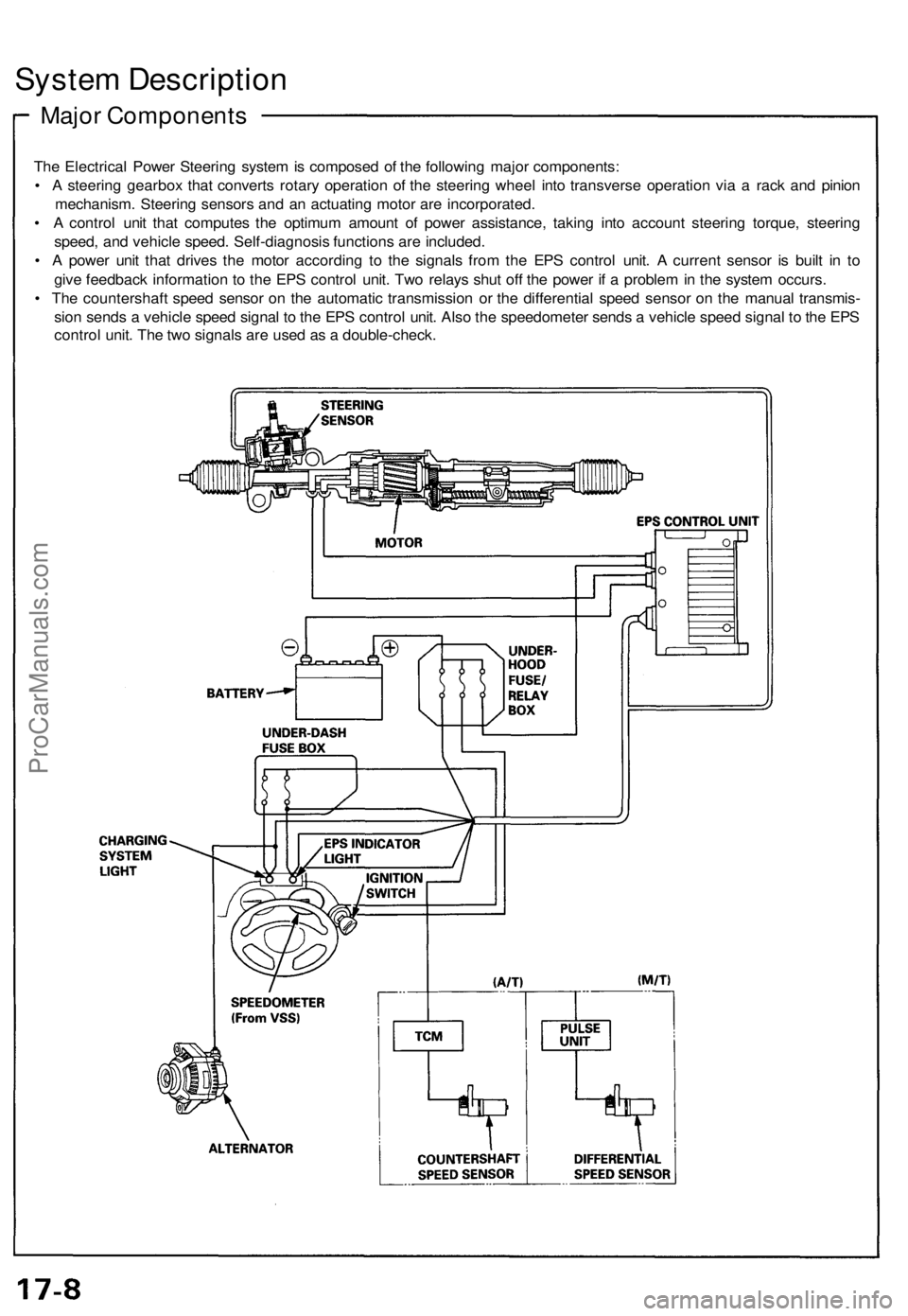
The Electrical Power Steering system is composed of the following major components:
• A steering gearbox that converts rotary operation of the steering wheel into transverse operation via a rack and pinion
mechanism. Steering sensors and an actuating motor are incorporated.
• A control unit that computes the optimum amount of power assistance, taking into account steering torque, steering
speed, and vehicle speed. Self-diagnosis functions are included.
• A power unit that drives the motor according to the signals from the EPS control unit. A current sensor is built in to
give feedback information to the EPS control unit. Two relays shut off the power if a problem in the system occurs.
• The countershaft speed sensor on the automatic transmission or the differential speed sensor on the manual transmis-
sion sends a vehicle speed signal to the EPS control unit. Also the speedometer sends a vehicle speed signal to the EPS
control unit. The two signals are used as a double-check.ProCarManuals.com
Page 558 of 1640
Steering angle sensor system check
1. Start the engine,
2. Push the TCS switch three times within three seconds.
NOTE: Always maintain the same number of rota-
tions.
3. Turn the steering wheel slowly from left to right more than 1.5 turns.
NOTE:
Start checking after the steering wheel moves at
least 1.5 turns from right to left.
Turn the steering wheel slowly, no faster than
one turn in four seconds.
4. Push the TCS switch twice within three seconds. NOTE: Always maintain the same number of rota-
tions.
5. Return the steering wheel to the left side slowly, and check the number of times the TCS indicator light
flashes after the wheel has moved approximately
one turn.
NOTE:
Start the check from the beginning when the steer-ing wheel moves at least one turn from left to
right, Turn the steering wheel slowly, no faster than one
turn in four seconds.
Standard number of times the TCS indicator light
flashes:
Manual Transmission: 5 times
Automatic Transmission: 2 times
6. If there is an abnormality, check the troubleshooting flowchart (see page 19-98('91-'93)('94-'96)
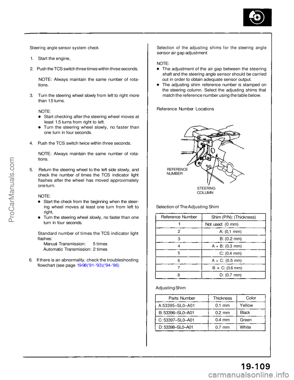
Selection of the adjusting shims for the steering angle
sensor air gap adjustment
NOTE:
The adjustment of the air gap between the steeringshaft and the steering angle sensor should be carried
out in order to obtain adequate sensor output.
The adjusting shim reference number is stamped on
the steering column. Select the adjusting shims that match the reference number using the table below.
Reference Number Locations
REFERENCE
NUMBER
STEERING
COLUMN
Selection of The Adjusting Shim
Adjusting Shim Parts Number
A:53395–SL0–A01
B: 53396–SL0–A01
C: 53397–SL0–A01
D: 53398–SL0–A01
Thickness
0.1 mm
0.2 mm
0.4 mm
0.7 mm
Color
Yellow
Black
Green
White
Reference Number
1
2
3
4
5
6
7
8
Shim (P/N): (Thickness)
Not used: (0 mm)
A:
(0,1
mm)
B:
(0.2
mm)
A + B:
(0.3
mm)
C:
(0.4
mm)
A + C:
(0.5
mm)
B + C:
(0.6
mm)
D:
(0.7
mm)ProCarManuals.com
Page 858 of 1640
G551 '93-'96 Models )
G551 '93-'96 Models)
Back-up Lights
Test
Manual Transmission:
1
.
If only one back-up right does not go on, check that
bul
b
in the taillight.
2
.
If neither back-up light goes on, check the No. 5 (15
A) fuse in the under-dash fuse box.
3
.
If the fuse and bulbs are OK, disconnect the connec- to
r
from the back-up light switch on the transmis-
sio
n
housing.
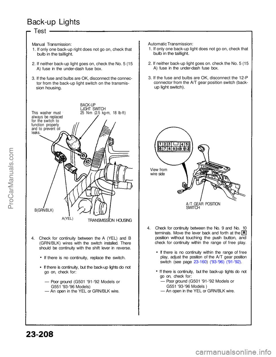
BACK-UP
LJGHT SWITCH
25 N·m (2.5 kg-m, 18 Ib-ft)
This washer must
always be replaced
for the switch to
function properly and to prevent oil
leaks.
B(GRN/BLK)
A(YEL)
TRANSMISSION HOUSING
4. Check for continuity between the A (YEL) and B (GRN/BLK) wires with the switch installed. There
should be continuity with the shift lever in reverse.
If there is no continuity, replace the switch.
If there is continuity, but the back-up lights do not
go on, check for:
— Poor ground (G501 '91-'92 Models or
— An open in the YEL or GRN/BLK wire. 4. Check for continuity between the No. 9 and No. 10 terminals. Move the lever back and forth at the
position without touching the push button, and
check for continuity within the range of free play.
If there is no continuity within the range of freeplay, adjust the position of the A/T gear position
switch (see page 23-160) ('93-'96) ('91-'92).
ff there is continuity, but the back-up tights do not go on, check for:
— Poor ground (G501 '91-'92 Models or
— An open in the YEL or GRN/BLK wire.
A/T GEAR POSITION
SWITCH
View from
wire side
Automatic Transmission:
1
.
If only one back-up light does not go on, check that
bul
b
in the taillight.
2
.
If neither back-up light goes on. check the No. 5 (15
A) fuse in the under-dash fuse box.
3
.
If the fuse and bulbs are OK, disconnect the 12-P
connector from the A/T gear position switch (back-
u
p
light switch).
ProCarManuals.com
Page 935 of 1640
Cruise Control
Description
The cruise control system uses mechanically and electri-
cally operated devices to maintain vehicle speed at a
setting selected by the driver.
The ECM receives command signals from the cruise con-
trol main switch and the cruise control set/resume switch.
It receives information about operating conditions from
the brake switch, vehicle speed sensor (VSS), the clutch
switch (with manual transmission), or the A/T gear posi-
tion switch (with automatic transmission). The ECM
sends operational signals to the devices that regulate the
throttle position. The throttle position maintains the
selected vehicle speed. Essentially, the ECM compares
the actual speed of the vehicle to the selected speed.
Then, it uses the result of that comparison to open or
close the throttle.
The brake switch releases the system's control of the
throttle at the instant the driver depresses the brake
pedal. The switch sends an electronic signal to the ECM
when the brake pedal is depressed; the ECM responds
by allowing the throttle to close. The clutch switch (man-
ual transmission) or the A/T gear position switch (auto-
matic transmission) sends a disengage signal to the
ECM that also allows the throttle to close.
Operation:
The cruise control system will set and automatically
maintain any speed above 25 mph (45 km/h). To set,
make sure that the main switch is in the "ON" position.
After reaching the desired speed, press the set switch.
The ECM will receive a set signal and, in turn, will actu-
ate the throttle valve control motor. When the set switch
is depressed and the cruise control system is on, the
"cruise control" ON indicator in the gauge assembly will
light up. You can cancel the cruise control system by
pushing the main switch to "OFF". This erases the set
speed from memory. If the system is disengaged tem-
porarily by the brake switch, clutch switch, or A/T gear
position switch and vehicle speed is still above 25 mph,
press the resume switch. With the resume switch
depressed and the set memory retained, the vehicle
automatically returns to the previous set speed.
For gradual acceleration without depressing the acceler-
ator pedal, push the resume switch down and hold it
there until the desired speed is reached. This will send
an acceleration signal to the ECM. When the switch is
released, the system will be reprogrammed for the new
speed. To slow down, depress the set switch. This will
send a deceleration signal to the ECM causing the car to
coast until the desired speed is reached. When the
desired speed is reached, release the set switch. This
will reprogram the system for the new speed.ProCarManuals.com
Page 968 of 1640
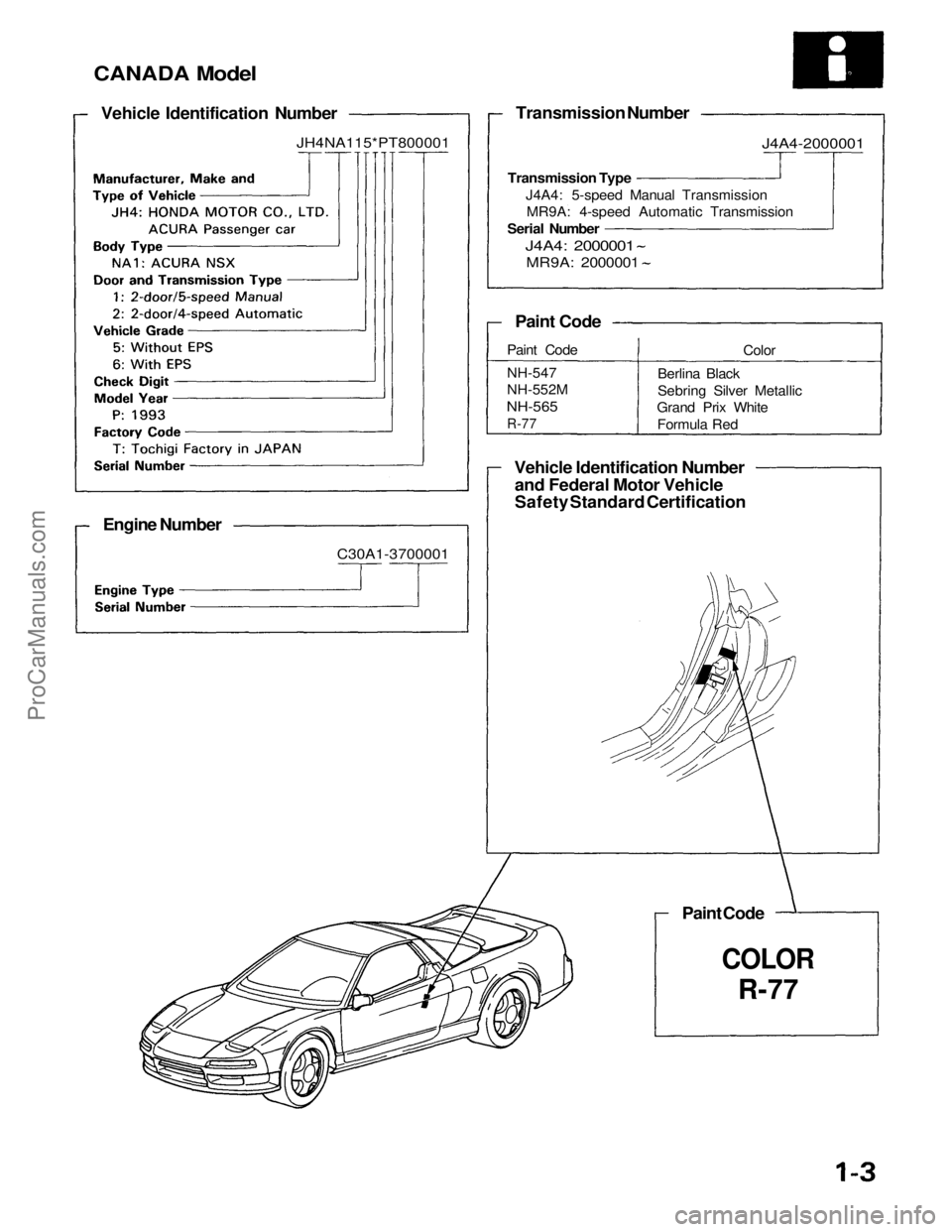
CANADA Model
Vehicle Identification Number
JH4NA115*PT800001
Engine Number
C30A1-3700001
Transmission Number
Transmission Type J4A4: 5-speed Manual TransmissionMR9A: 4-speed Automatic Transmission
Serial Number
J4A4: 2000001
MR9A: 2000001
Paint Code
Paint Code
NH-547
NH-552M
NH-565
R-77
Color
Berlina Black
Sebring Silver Metallic
Grand Prix White
Formula Red
Vehicle Identification Number and Federal Motor Vehicle
Safety Standard Certification
Paint Code
COLOR
R-77
J4A4-2000001ProCarManuals.com
Page 973 of 1640
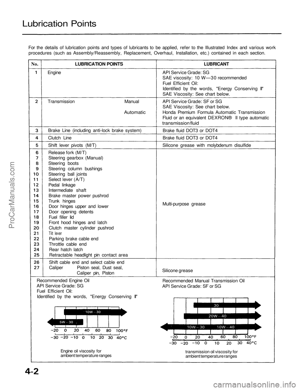
Lubrication Points
For the details of lubrication points and types of lubricants to be applied, refer to the Illustrated Index and various workprocedures (such as Assembly/Reassembly, Replacement, Overhaul, Installation, etc.) contained in each section.
No.
LUBRICATION POINTS
LUBRICANT
Engine
Transmission
Manual
Automatic
Brake Line (including anti-lock brake system)
Clutch Line Shift lever pivots (M/T)Release fork (M/T)Steering gearbox (Manual)
Steering boots Steering column bushings
Steering ball jointsSelect lever (A/T)
Pedal linkage Intermediate shaft
Brake master power pushrod
Trunk hinges Door hinges upper and lower
Door opening detents
Fuel filler lid
Front hood hinges and latch
Clutch master cylinder pushrod
Tilt lever
Parking brake cable end
Throttle cable end Rear hatch latchRetractable headlight pin contact area
Shift cable end and select cable end
Caliper Piston seal, Dust seal, Caliper pin, Piston
Recommended Engine Oil
API Service Grade: SG Fuel Efficient Oil:
Identified by the words, "Energy Conserving II" API Service Grade: SG
SAE viscosity: 10 W—30 recommended
Fuel Efficient Oil:
Identified by the words, "Energy Conserving II"
SAE Viscosity: See chart below.
API Service Grade: SF or SG SAE Viscosity: See chart below.
Honda Premium Formula Automatic Transmission
Fluid or an equivalent DEXRON® II type automatic
transmission fluid
Brake fluid DOT3 or DOT4
Brake fluid DOT3 or DOT4
Silicone grease with molybdenum disulfide
Multi-purpose grease
Silicone grease Recommended Manual Transmission Oil
API Service Grade: SF or SG
transmission oil viscosity forambient temperature ranges
Engine oil viscosity for
ambient temperature rangesProCarManuals.com
Page 981 of 1640
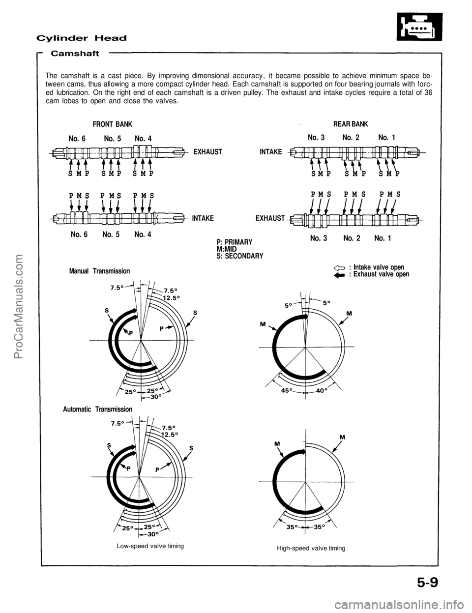
Cylinder Head
Camshaft
The camshaft is a cast piece. By improving dimensional accuracy, it became possible to achieve minimum space be-
tween cams, thus allowing a more compact cylinder head. Each camshaft is supported on four bearing journals with forc-
ed lubrication. On the right end of each camshaft is a driven pulley. The exhaust and intake cycles require a total of 36
cam lobes to open and close the valves.
FRONT BANK
No. 6 No. 5 No. 4
S M P S M P S M P
P M S P M S P M S
EXHAUST INTAKE
S M P S M P S M P
P M S P M S P M S
REAR BANK
No. 3 No. 2 No. 1
No. 3 No. 2 No. 1
No. 6 No. 5 No. 4
INTAKE EXHAUST
P: PRIMARY
M:MID
S: SECONDARY
: Intake valve open
: Exhaust valve open
Manual Transmission
Automatic Transmission
Low-speed valve timing
High-speed valve timingProCarManuals.com
Page 1099 of 1640
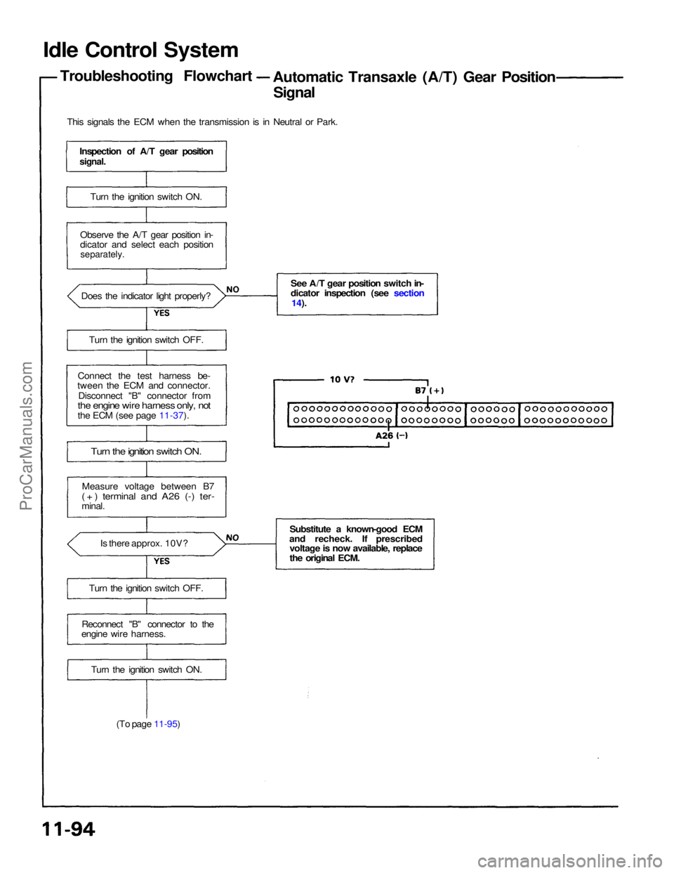
Idle Control System
Troubleshooting Flowchart Automatic Transaxle (A/T) Gear Position
Signal
This signals the ECM when the transmission is in Neutral or Park.
Inspection of A/T gear position
signal.
Turn the ignition switch ON.
Observe the A/T gear position in-
dicator and select each position
separately.
Does the indicator light properly?
Turn the ignition switch OFF.
Connect the test harness be-
tween the ECM and connector.
Disconnect "B" connector from
the engine wire harness only, not
the ECM (see page 11-37).
Turn the ignition switch ON.
Measure voltage between B7
( + ) terminal and A26 (-) ter-
minal.
Is there approx. 10V?
Turn the ignition switch OFF.
Reconnect "B" connector to the
engine wire harness.
Turn the ignition switch ON.
(To page 11-95) See A/T gear position switch in-
dicator inspection (see section
14).
Substitute a known-good ECM
and recheck. If prescribed voltage is now available, replace
the original ECM.ProCarManuals.com
Page 1165 of 1640
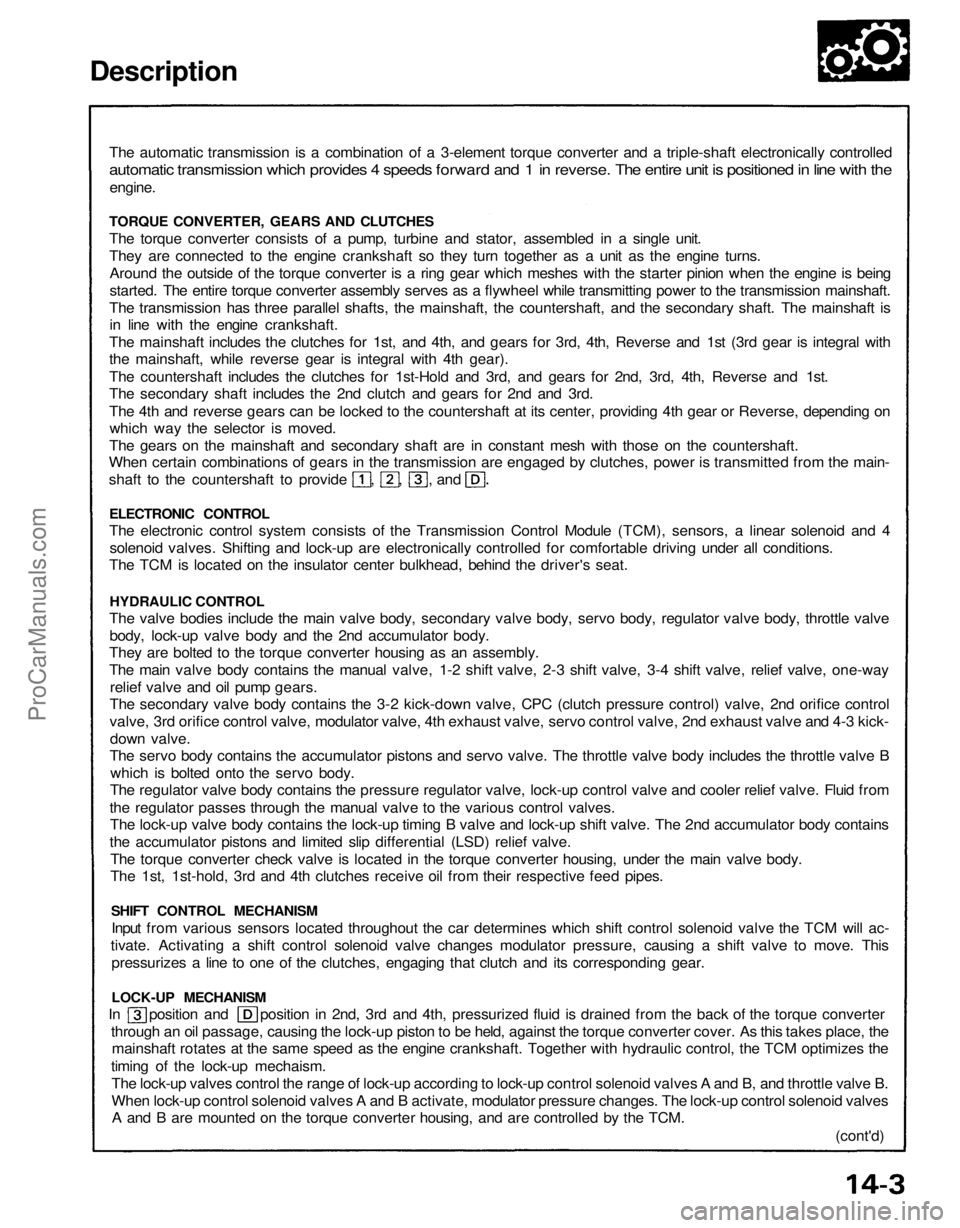
Description
The automatic transmission is a combination of a 3-element torque converter and a triple-shaft electronically controlled
automatic transmission which provides 4 speeds forward and 1 in reverse. The entire unit is positioned in line with the
engine.
TORQUE CONVERTER, GEARS AND CLUTCHES
The torque converter consists of a pump, turbine and stator, assembled in a single unit.
They are connected to the engine crankshaft so they turn together as a unit as the engine turns.
Around the outside of the torque converter is a ring gear which meshes with the starter pinion when the engine is being
started. The entire torque converter assembly serves as a flywheel while transmitting power to the transmission mainshaft.
The transmission has three parallel shafts, the mainshaft, the countershaft, and the secondary shaft. The mainshaft is
in line with the engine crankshaft.
The mainshaft includes the clutches for 1st, and 4th, and gears for 3rd, 4th, Reverse and 1st (3rd gear is integral with
the mainshaft, while reverse gear is integral with 4th gear).
The countershaft includes the clutches for 1st-Hold and 3rd, and gears for 2nd, 3rd, 4th, Reverse and 1st.
The secondary shaft includes the 2nd clutch and gears for 2nd and 3rd.
The 4th and reverse gears can be locked to the countershaft at its center, providing 4th gear or Reverse, depending on
which way the selector is moved.
The gears on the mainshaft and secondary shaft are in constant mesh with those on the countershaft.
When certain combinations of gears in the transmission are engaged by clutches, power is transmitted from the main-
shaft to the countershaft to provide , , , and
ELECTRONIC CONTROL
The electronic control system consists of the Transmission Control Module (TCM), sensors, a linear solenoid and 4
solenoid valves. Shifting and lock-up are electronically controlled for comfortable driving under all conditions.
The TCM is located on the insulator center bulkhead, behind the driver's seat.
HYDRAULIC CONTROL
The valve bodies include the main valve body, secondary valve body, servo body, regulator valve body, throttle valve
body, lock-up valve body and the 2nd accumulator body.
They are bolted to the torque converter housing as an assembly.
The main valve body contains the manual valve, 1-2 shift valve, 2-3 shift valve, 3-4 shift valve, relief valve, one-way
relief valve and oil pump gears.
The secondary valve body contains the 3-2 kick-down valve, CPC (clutch pressure control) valve, 2nd orifice control
valve, 3rd orifice control valve, modulator valve, 4th exhaust valve, servo control valve, 2nd exhaust valve and 4-3 kick-
down valve.
The servo body contains the accumulator pistons and servo valve. The throttle valve body includes the throttle valve B
which is bolted onto the servo body.
The regulator valve body contains the pressure regulator valve, lock-up control valve and cooler relief valve. Fluid from
the regulator passes through the manual valve to the various control valves.
The lock-up valve body contains the lock-up timing B valve and lock-up shift valve. The 2nd accumulator body contains
the accumulator pistons and limited slip differential (LSD) relief valve.
The torque converter check valve is located in the torque converter housing, under the main valve body.
The 1st, 1st-hold, 3rd and 4th clutches receive oil from their respective feed pipes.
SHIFT CONTROL MECHANISM
Input from various sensors located throughout the car determines which shift control solenoid valve the TCM will ac-
tivate. Activating a shift control solenoid valve changes modulator pressure, causing a shift valve to move. This
pressurizes a line to one of the clutches, engaging that clutch and its corresponding gear.
LOCK-UP MECHANISM
In position and position in 2nd, 3rd and 4th, pressurized fluid is drained from the back of the torque converter
through an oil passage, causing the lock-up piston to be held, against the torque converter cover. As this takes place, the
mainshaft rotates at the same speed as the engine crankshaft. Together with hydraulic control, the TCM optimizes the
timing of the lock-up mechaism.
The lock-up valves control the range of lock-up according to lock-up control solenoid valves A and B, and throttle valve B.
When lock-up control solenoid valves A and B activate, modulator pressure changes. The lock-up control solenoid valves
A and B are mounted on the torque converter housing, and are controlled by the TCM.
(cont'd)ProCarManuals.com