boot ACURA NSX 1991 Service Repair Manual
[x] Cancel search | Manufacturer: ACURA, Model Year: 1991, Model line: NSX, Model: ACURA NSX 1991Pages: 1640, PDF Size: 60.48 MB
Page 288 of 1640
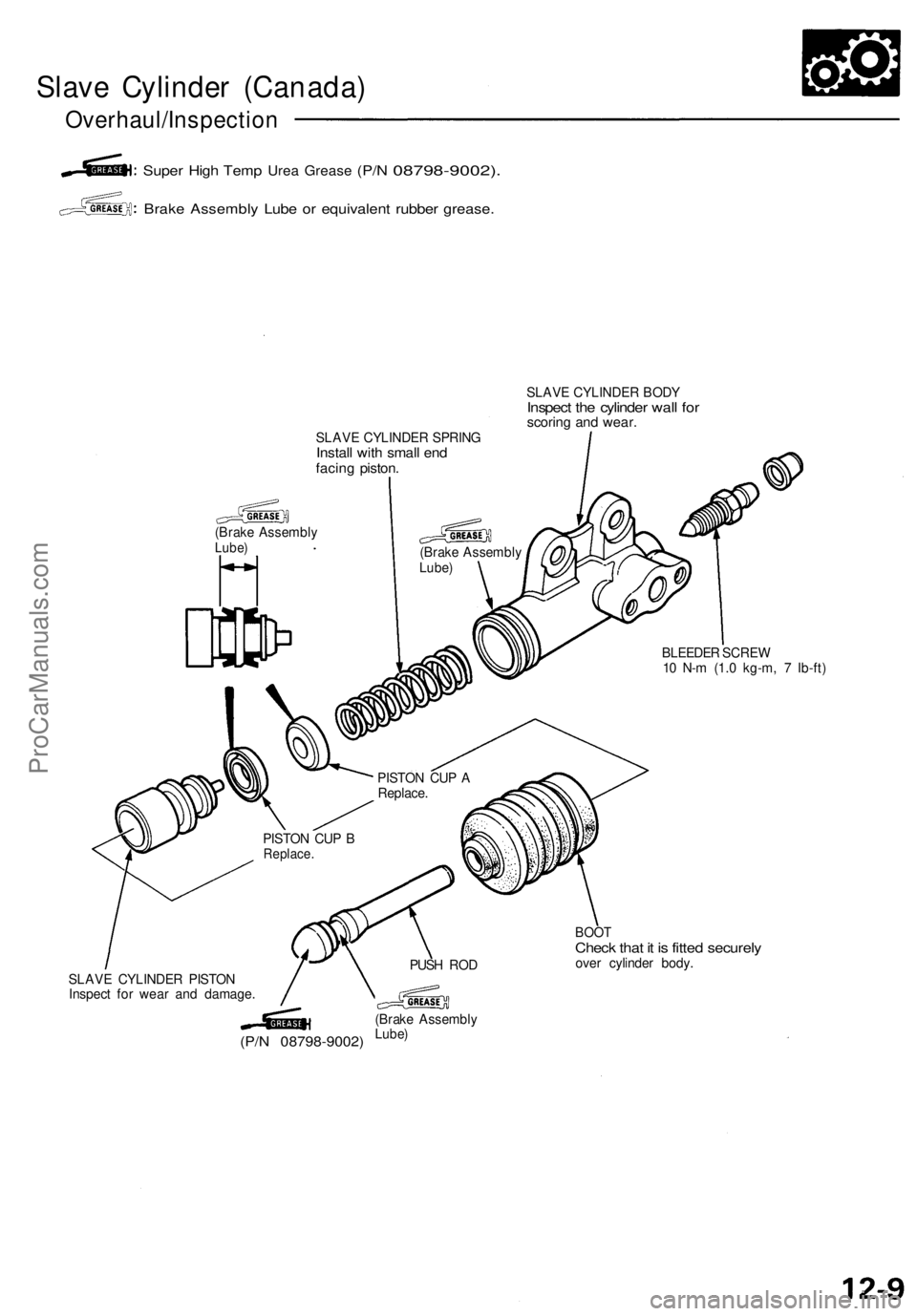
Slave Cylinder (Canada)
Overhaul/Inspection
Super High Temp
Urea
Grease
(P/N
08798-9002).
Brake Assembly Lube or equivalent rubber grease.
SLAVE CYLINDER SPRING
Install with small end
facing piston.
(Brake Assembly
Lube)
SLAVE CYLINDER BODY
Inspect the cylinder wall for
scoring and wear.
(Brake Assembly
Lube)
BLEEDER SCREW
10 N-m (1.0 kg-m, 7 Ib-ft)
SLAVE CYLINDER PISTON
Inspect for wear and damage.
(P/N 08798-9002)
(Brake Assembly
Lube)
BOOT
Check that it is fitted securely
over cylinder body.
PUSH ROD
PISTON CUP B
Replace.
PISTON CUP A
Replace.ProCarManuals.com
Page 387 of 1640
Driveshafts
Removal
INSPECTIO N
Driveshaf t Boo t
Chec k th e boot s o n th e driveshaf t fo r cracks , damage ,
leakin g greas e an d loos e boo t bands .
I f an y damag e i s found , replac e th e boot .
Splin e Loosenes s
Tur n th e driveshaf t b y hand , an d mak e sur e th e spline s
an d joint s ar e no t excessivel y loose .
I f damag e i s found , replac e th e joint s i f necessary .
Twiste d o r Cracke d
Mak e sur e th e driveshaf t i s no t twiste d o r cracked .
Replac e if necessary .
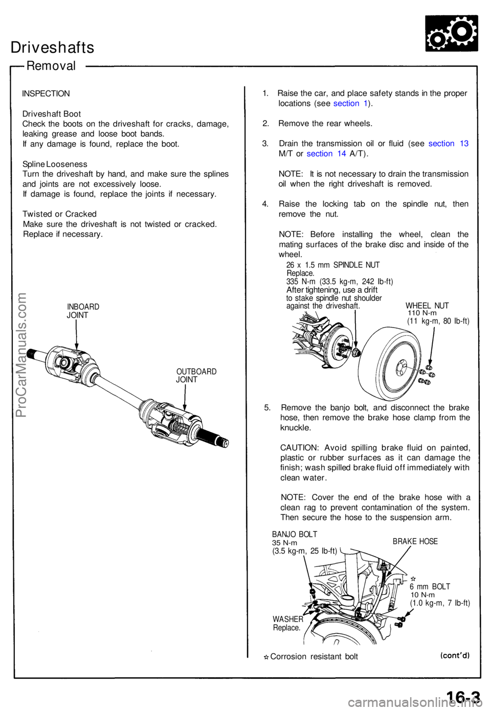
INBOARDJOINT
OUTBOAR DJOINT
1. Rais e th e car , an d plac e safet y stand s in th e prope r
location s (se e sectio n 1 ).
2 . Remov e th e rea r wheels .
3 . Drai n th e transmissio n oi l o r flui d (se e sectio n 1 3
M/ T o r sectio n 1 4 A/T) .
NOTE : I t i s no t necessar y t o drai n th e transmissio n
oi l whe n th e righ t driveshaf t i s removed .
4 . Rais e th e lockin g ta b o n th e spindl e nut , the n
remov e th e nut .
NOTE : Befor e installin g th e wheel , clea n th e
matin g surface s of the brak e dis c an d insid e of the
wheel .
26 x 1. 5 m m SPINDL E NU TReplace .335 N- m (33. 5 kg-m , 24 2 Ib-ft )After tightening , us e a drif tto stak e spindl e nu t shoulde ragainst th e driveshaft . WHEE L NU T110 N- m(11 kg-m , 8 0 Ib-ft )
5. Remov e th e banj o bolt , an d disconnec t th e brak e
hose , the n remov e th e brak e hos e clam p fro m th e
knuckle .
CAUTION : Avoi d spillin g brak e flui d o n painted ,
plasti c o r rubbe r surface s a s i t ca n damag e th e
finish ; was h spille d brak e flui d of f immediatel y wit h
clea n water .
NOTE : Cove r th e en d o f th e brak e hos e wit h a
clea n ra g t o preven t contaminatio n of the system.
The n secur e th e hos e t o th e suspensio n arm .
BANJ O BOL T35 N- m(3.5 kg-m , 2 5 Ib-ft )
BRAK E HOS E
WASHE RReplace.
Corrosio n resistan t bol t
6 m m BOL T10 N- m(1.0 kg-m , 7 Ib-ft )
ProCarManuals.com
Page 390 of 1640
Driveshafts
Disassembly
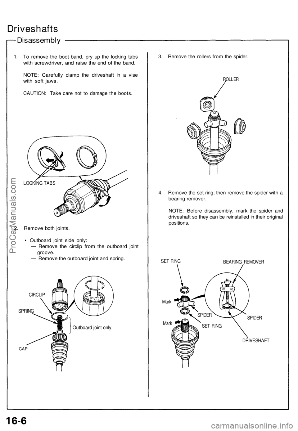
1. To remove the boot band, pry up the locking tabs
with screwdriver, and raise the end of the band.
NOTE: Carefully clamp the driveshaft in a vise
with soft jaws.
CAUTION: Take care not to damage the boots.
LOCKING TABS
2. Remove both joints.
• Outboard joint side only:
— Remove the circlip from the outboard joint
groove.
— Remove the outboard joint and spring.
CIRCLIP
SPRING
CAP
Outboard joint only.
3. Remove the rollers from the spider.
ROLLER
4. Remove the set ring; then remove the spider with a
bearing remover.
NOTE: Before disassembly, mark the spider and
driveshaft so they can be reinstalled in their original
positions.
SET RING
BEARING REMOVER
Mark
Mark
SPIDER
DRIVESHAFT
SPIDER
SET RINGProCarManuals.com
Page 391 of 1640
Inspection
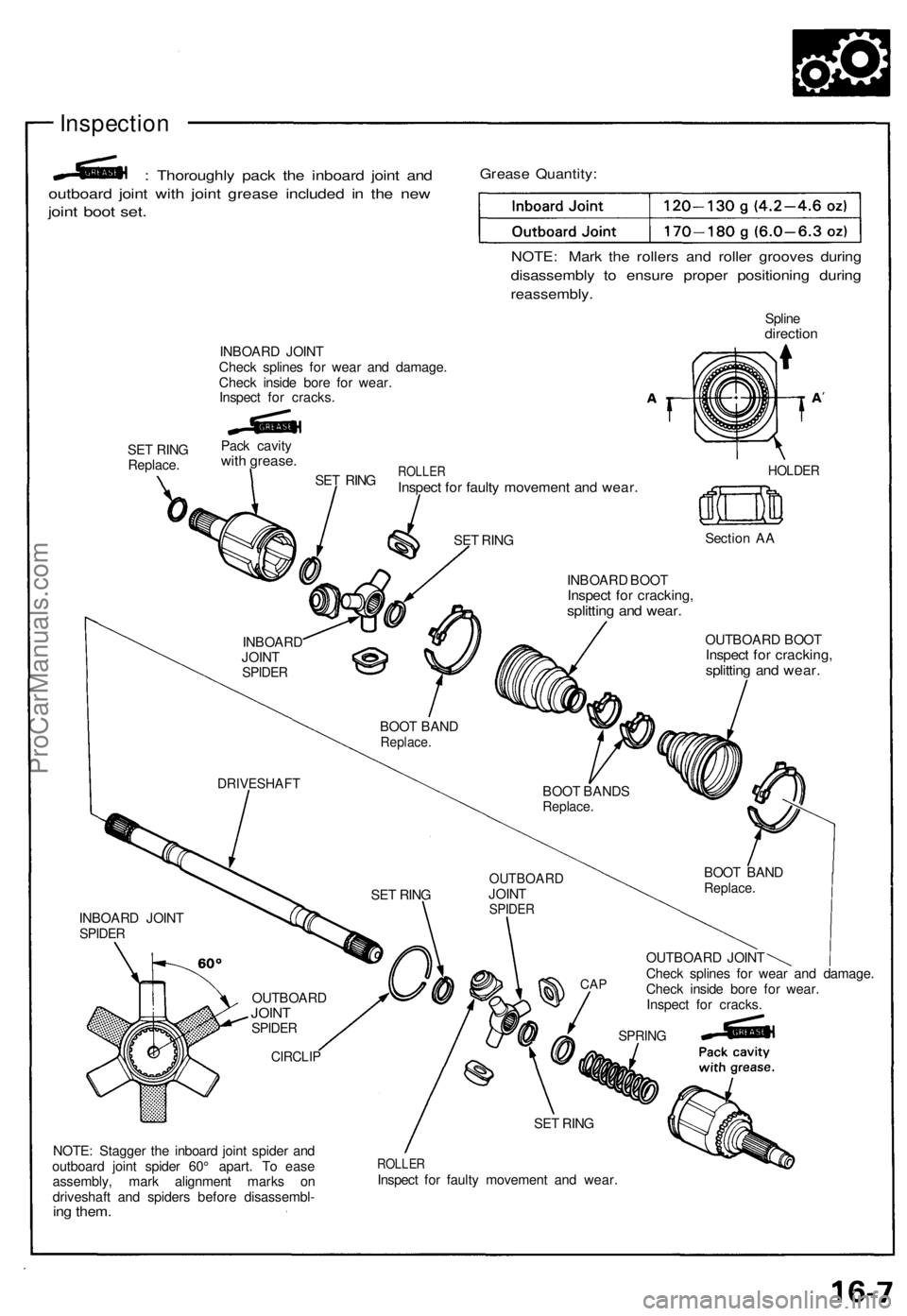
: Thoroughly pack the inboard joint and
outboard joint with joint grease included in the new
joint boot set.
Grease Quantity:
NOTE: Mark the rollers and roller grooves during
disassembly to ensure proper positioning during
reassembly.
Spline
direction
INBOARD JOINT
Check splines for wear and damage.
Check inside bore for wear.
Inspect for cracks.
SET RING
Replace.
Pack cavity
with grease.
SET RING
ROLLER
Inspect for faulty movement and wear.
HOLDER
Section AA
INBOARD BOOT
Inspect for cracking,
splitting and wear.
OUTBOARD BOOT
Inspect for cracking,
splitting and wear.
OUTBOARD JOINT
Check splines for wear and damage.
Check inside bore for wear.
Inspect for cracks.
NOTE: Stagger the inboard joint spider and
outboard joint spider 60° apart. To ease
assembly, mark alignment marks on
driveshaft and spiders before disassembl-
ing them.
ROLLER
Inspect for faulty movement and wear.
DRIVESHAFT
SET RING
OUTBOARD
JOINT
SPIDER
CAP
SPRING
SET RING
CIRCLIP
OUTBOARD
JOINT
SPIDER
INBOARD JOINT
SPIDER
BOOT BAND
Replace.
BOOT BANDS
Replace.
BOOT BAND
Replace.
INBOARD
JOINT
SPIDER
SET RINGProCarManuals.com
Page 392 of 1640
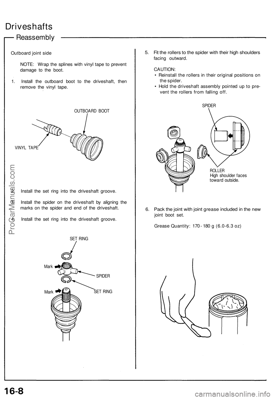
Driveshafts
Reassembl y
Outboard join t sid e
NOTE : Wra p th e spline s wit h viny l tap e t o preven t
damag e t o th e boot .
1 . Instal l th e outboar d boo t t o th e driveshaft , the n
remov e th e viny l tape .
OUTBOAR D BOO T
VINY L TAP E
2. Instal l th e se t rin g int o th e driveshaf t groove .
3 . Instal l th e spide r o n th e driveshaf t b y alignin g th e
mark s o n th e spide r an d en d o f th e driveshaft .
4 . Instal l th e se t rin g int o th e driveshaf t groove .
SET RIN G
Mar k
Mark
SPIDE R
SE T RIN G
5. Fi t th e roller s to th e spide r wit h thei r hig h shoulder s
facing outward .
CAUTION :
• Reinstal l th e roller s in thei r origina l position s o n
th e spider .
• Hol d th e driveshaf t assembl y pointe d u p t o pre -
ven t th e roller s fro m fallin g off .
SPIDE R
ROLLE RHigh shoulde r face stowar d outside .
6. Pac k th e join t wit h join t greas e include d in th e ne w
join t boo t set .
Greas e Quantity : 17 0 - 18 0 g (6.0-6. 3 oz)
ProCarManuals.com
Page 393 of 1640
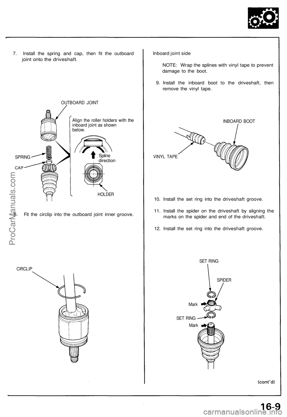
7. Install the spring and cap, then fit the outboard
joint onto the driveshaft.
OUTBOARD JOINT
Align the roller holders with the
inboard joint as shown
below.
Spline
direction
HOLDER
8. Fit the circlip into the outboard joint inner groove.
CIRCLIP
Inboard joint side
NOTE: Wrap the splines with vinyl tape to prevent
damage to the boot.
9. Install the inboard boot to the driveshaft, then
remove the vinyl tape.
INBOARD BOOT
VINYL TAPE
10. Install the set ring into the driveshaft groove.
11. Install the spider on the driveshaft by aligning the
marks on the spider and end of the driveshaft.
12. Install the set ring into the driveshaft groove.
SET RING
Mark
SET RING
Mark
SPIDER
SPRING
CAPProCarManuals.com
Page 394 of 1640
Driveshafts
Reassembl y
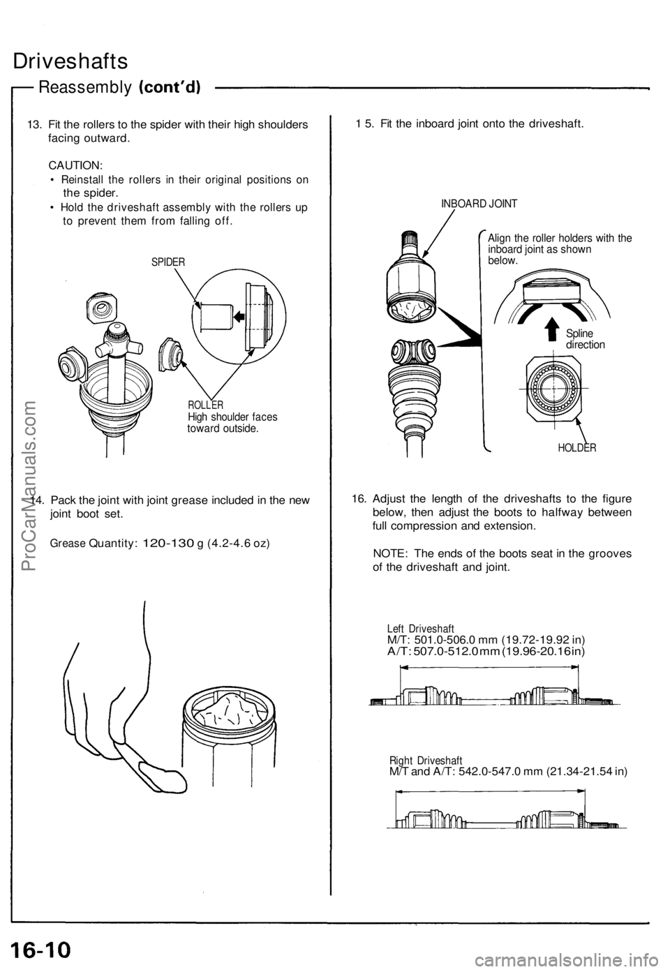
13. Fi t th e roller s t o th e spide r wit h thei r hig h shoulder s
facin g outward .
CAUTION :
• Reinstal l th e roller s i n thei r origina l position s o n
the spider .
• Hol d th e driveshaf t assembl y wit h th e roller s u p
to preven t the m fro m fallin g off .
SPIDE R
ROLLE RHigh shoulde r face stowar d outside .
14. Pac k th e join t wit h join t greas e include d in th e ne w
join t boo t set .
Greas e Quantity : 120-130 g (4.2-4. 6 oz)
1 5 . Fi t th e inboar d join t ont o th e driveshaft .
INBOARD JOIN T
Align th e rolle r holder s wit h th einboar d join t a s show nbelow.
HOLDE R
16. Adjus t th e lengt h o f th e driveshaft s t o th e figur e
below , the n adjus t th e boot s t o halfwa y betwee n
ful l compressio n an d extension .
NOTE : Th e end s o f th e boot s sea t i n th e groove s
o f th e driveshaf t an d joint .
Left Driveshaf tM/T: 501.0-506. 0 m m (19.72-19.9 2 in )A/T : 507.0-512. 0 m m (19.96-20.1 6 in )
Righ t Driveshaf tM/T an d A/T : 542.0-547. 0 m m (21.34-21.5 4 in )
Splin edirectio n
ProCarManuals.com
Page 395 of 1640
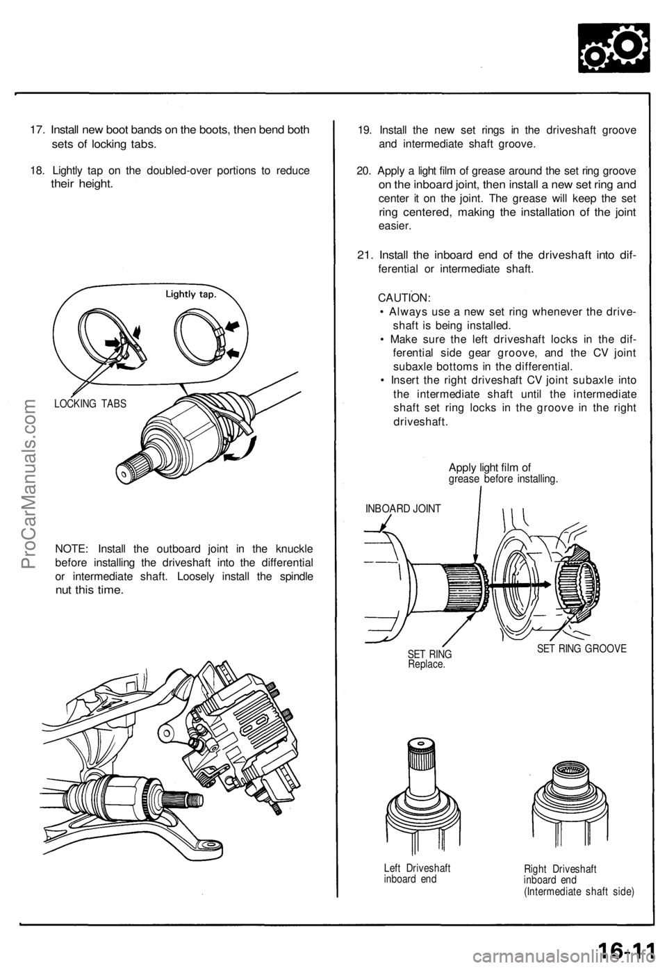
17. Install new boot bands on the boots, then bend both
sets of locking tabs.
18. Lightly tap on the doubled-over portions to reduce
their height.
NOTE: Install the outboard joint in the knuckle
before installing the driveshaft into the differential
or intermediate shaft. Loosely install the spindle
nut this time.
19. Install the new set rings in the driveshaft groove
and intermediate shaft groove.
20. Apply a light film of grease around the set ring groove
on the inboard joint, then install a new set ring and
center it on the joint. The grease will keep the set
ring centered, making the installation of the joint
easier.
21. Install the inboard end of the driveshaft into dif-
ferential or intermediate shaft.
CAUTION:
• Always use a new set ring whenever the drive-
shaft is being installed.
• Make sure the left driveshaft locks in the dif-
ferential side gear groove, and the CV joint
subaxle bottoms in the differential.
• Insert the right driveshaft CV joint subaxle into
the intermediate shaft until the intermediate
shaft set ring locks in the groove in the right
driveshaft.
Apply light film of
grease before installing.
INBOARD JOINT
SET RING
Replace.
SET RING GROOVE
Left Driveshaft
inboard end
Right Driveshaft
inboard end
(Intermediate shaft side)
LOCKING TABSProCarManuals.com
Page 437 of 1640
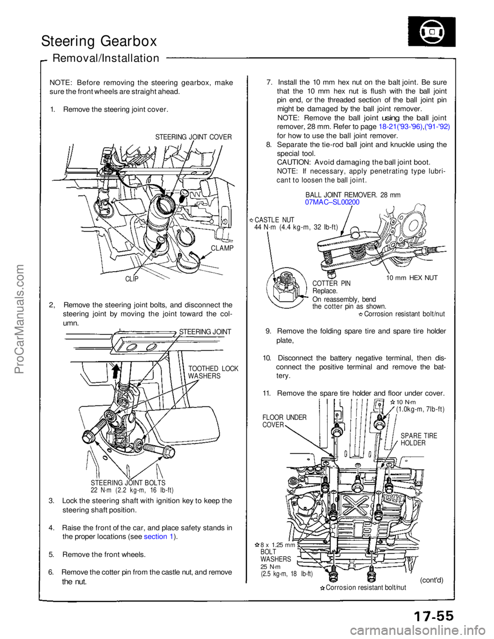
Steering Gearbox
Removal/Installation
NOTE: Before removing the steering gearbox, make
sure the front wheels are straight ahead. 1. Remove the steering joint cover.
STEERING JOINT COVER
7. Install the 10 mm hex nut on the balt joint. Be sure
that the 10 mm hex nut is flush with the ball joint
pin end, or the threaded section of the ball joint pin
might be damaged by the ball joint remover.
NOTE: Remove
the
ball
joint
using
the
ball
joint
remover, 28 mm. Refer to page 18-21('93-'96),('91-'92)
for how to use the ball joint remover.
8. Separate the tie-rod ball joint and knuckle using the
special tool.
CAUTION: Avoid damaging the ball joint boot.
NOTE: If necessary, apply penetrating type lubri-
cant to loosen the ball joint.
BALL JOINT REMOVER. 28 mm
07MAC–SL00200
CASTLE NUT
44 N·m (4.4 kg-m, 32 Ib-ft)
10 mm HEX NUT
CLAMP
CLIP
COTTER PIN
Replace.
On reassembly, bend
the cotter pin as shown.
Corrosion resistant bolt/nut
9. Remove the folding spare tire and spare tire holder plate,
10. Disconnect the battery negative terminal, then dis- connect the positive terminal and remove the bat-
tery.
11. Remove the spare tire holder and floor under cover.
FLOOR UNDER
COVER
10 N·m
(1.0kg-m, 7lb-ft)
SPARE TIRE
HOLDER
2, Remove the steering joint bolts, and disconnect the
steering joint by moving the joint toward the col-
umn.
STEERING JOINT
TOOTHED LOCK
WASHERS
STEERING JOINT BOLTS
22 N·m (2.2 kg-m, 16 Ib-ft)
3. Lock the steering shaft with ignition key to keep the steering shaft position.
4. Raise the front of the car, and place safety stands in the proper locations (see section 1).
5. Remove the front wheels.
6. Remove the cotter pin from the castle nut, and remove
the
nut.
8 x
1.25
mm
BOLT
WASHERS
25 N·m
(2.5 kg-m, 18 lb-ft)
Corrosion resistant bolt/nut
(cont'd)ProCarManuals.com
Page 441 of 1640
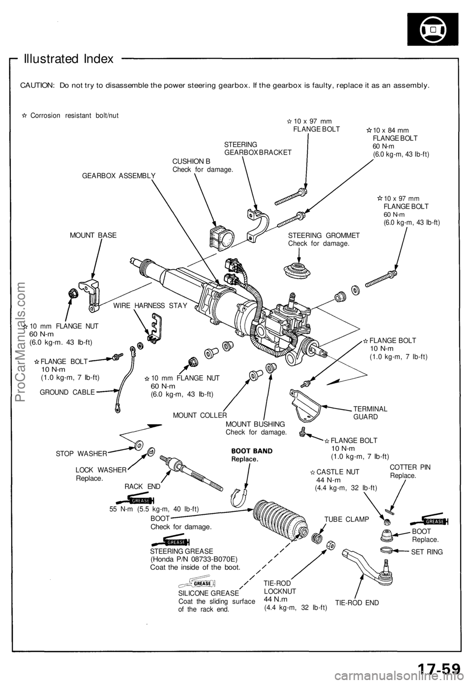
Illustrated Inde x
CAUTION : D o no t tr y to disassembl e th e powe r steerin g gearbox . I f th e gearbo x is faulty , replac e it a s a n assembly .
Corrosion resistan t bolt/nu t10 x 97 m mFLANG E BOL T
GEARBO X ASSEMBL Y STEERIN
G
GEARBO X BRACKE T
CUSHION BChec k fo r damage .
10 x 84 m mFLANG E BOL T60 N- m(6.0 kg-m , 4 3 Ib-ft )
10 x 97 m mFLANG E BOL T60 N- m(6.0 kg-m , 4 3 Ib-ft )
MOUN T BAS E
10 m m FLANG E NU T60 N- m(6.0 kg-m . 4 3 Ib-ft )
FLANG E BOL T10 N- m(1.0 kg-m , 7 Ib-ft )
GROUN D CABL E
STO P WASHE R
LOC K WASHE R
Replace.RACK EN D
TIE-ROD EN D
STEERIN
G GROMME T
Chec k fo r damage .
WIR E HARNES S STA Y
1 0 m m FLANG E NU T
60 N- m(6.0 kg-m , 4 3 Ib-ft )
FLANG E BOL T10 N- m(1.0 kg-m , 7 Ib-ft )
MOUN T COLLE R
MOUNT BUSHIN GCheck fo r damage .
FLANGE BOL T
10 N- m(1.0 kg-m , 7 Ib-ft )
TERMINA L
GUAR D
COTTE R PI N
Replace .
CASTL
E NU T
44 N- m(4.4 kg-m , 3 2 Ib-ft )
TUB E CLAM P
BOOT
Replace .
SE T RIN G
STEERIN
G GREAS E
(Honda P/ N 08733-B070E )Coat th e insid e o f th e boot .
SILICON E GREAS E
Coa t th e slidin g surfac e
o f th e rac k end .
TIE-RO DLOCKNU T44 N.m(4.4 kg-m , 3 2 Ib-ft )
5
5 N- m (5. 5 kg-m , 4 0 Ib-ft )
BOO T
Chec k fo r damage .
ProCarManuals.com