automatic transmission fluid ACURA NSX 1991 Service Repair Manual
[x] Cancel search | Manufacturer: ACURA, Model Year: 1991, Model line: NSX, Model: ACURA NSX 1991Pages: 1640, PDF Size: 60.48 MB
Page 973 of 1640
Lubrication Points
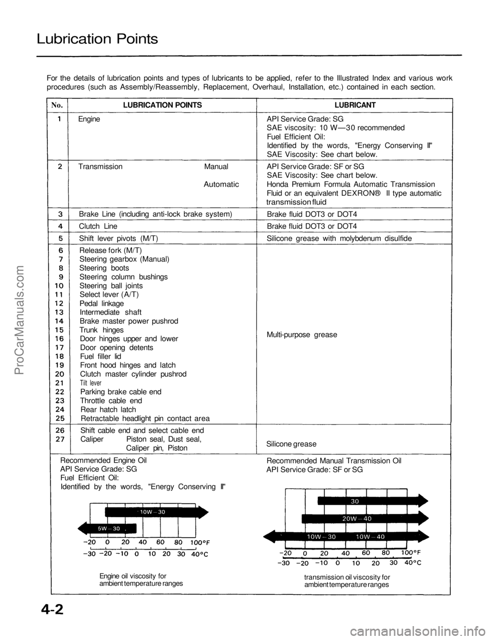
For the details of lubrication points and types of lubricants to be applied, refer to the Illustrated Index and various workprocedures (such as Assembly/Reassembly, Replacement, Overhaul, Installation, etc.) contained in each section.
No.
LUBRICATION POINTS
LUBRICANT
Engine
Transmission
Manual
Automatic
Brake Line (including anti-lock brake system)
Clutch Line Shift lever pivots (M/T)Release fork (M/T)Steering gearbox (Manual)
Steering boots Steering column bushings
Steering ball jointsSelect lever (A/T)
Pedal linkage Intermediate shaft
Brake master power pushrod
Trunk hinges Door hinges upper and lower
Door opening detents
Fuel filler lid
Front hood hinges and latch
Clutch master cylinder pushrod
Tilt lever
Parking brake cable end
Throttle cable end Rear hatch latchRetractable headlight pin contact area
Shift cable end and select cable end
Caliper Piston seal, Dust seal, Caliper pin, Piston
Recommended Engine Oil
API Service Grade: SG Fuel Efficient Oil:
Identified by the words, "Energy Conserving II" API Service Grade: SG
SAE viscosity: 10 W—30 recommended
Fuel Efficient Oil:
Identified by the words, "Energy Conserving II"
SAE Viscosity: See chart below.
API Service Grade: SF or SG SAE Viscosity: See chart below.
Honda Premium Formula Automatic Transmission
Fluid or an equivalent DEXRON® II type automatic
transmission fluid
Brake fluid DOT3 or DOT4
Brake fluid DOT3 or DOT4
Silicone grease with molybdenum disulfide
Multi-purpose grease
Silicone grease Recommended Manual Transmission Oil
API Service Grade: SF or SG
transmission oil viscosity forambient temperature ranges
Engine oil viscosity for
ambient temperature rangesProCarManuals.com
Page 1165 of 1640
Description
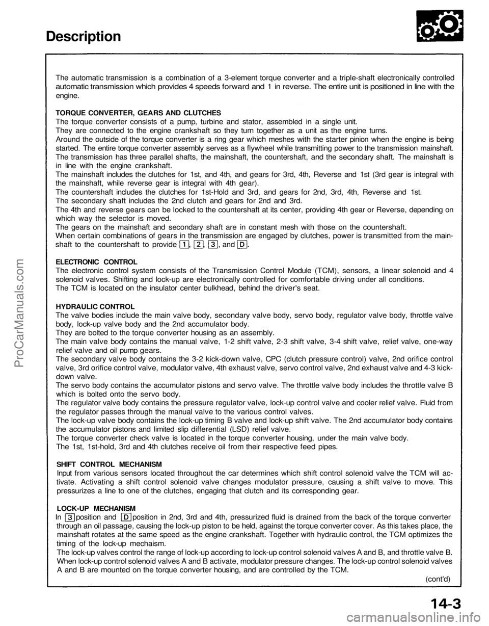
The automatic transmission is a combination of a 3-element torque converter and a triple-shaft electronically controlled
automatic transmission which provides 4 speeds forward and 1 in reverse. The entire unit is positioned in line with the
engine.
TORQUE CONVERTER, GEARS AND CLUTCHES
The torque converter consists of a pump, turbine and stator, assembled in a single unit.
They are connected to the engine crankshaft so they turn together as a unit as the engine turns.
Around the outside of the torque converter is a ring gear which meshes with the starter pinion when the engine is being
started. The entire torque converter assembly serves as a flywheel while transmitting power to the transmission mainshaft.
The transmission has three parallel shafts, the mainshaft, the countershaft, and the secondary shaft. The mainshaft is
in line with the engine crankshaft.
The mainshaft includes the clutches for 1st, and 4th, and gears for 3rd, 4th, Reverse and 1st (3rd gear is integral with
the mainshaft, while reverse gear is integral with 4th gear).
The countershaft includes the clutches for 1st-Hold and 3rd, and gears for 2nd, 3rd, 4th, Reverse and 1st.
The secondary shaft includes the 2nd clutch and gears for 2nd and 3rd.
The 4th and reverse gears can be locked to the countershaft at its center, providing 4th gear or Reverse, depending on
which way the selector is moved.
The gears on the mainshaft and secondary shaft are in constant mesh with those on the countershaft.
When certain combinations of gears in the transmission are engaged by clutches, power is transmitted from the main-
shaft to the countershaft to provide , , , and
ELECTRONIC CONTROL
The electronic control system consists of the Transmission Control Module (TCM), sensors, a linear solenoid and 4
solenoid valves. Shifting and lock-up are electronically controlled for comfortable driving under all conditions.
The TCM is located on the insulator center bulkhead, behind the driver's seat.
HYDRAULIC CONTROL
The valve bodies include the main valve body, secondary valve body, servo body, regulator valve body, throttle valve
body, lock-up valve body and the 2nd accumulator body.
They are bolted to the torque converter housing as an assembly.
The main valve body contains the manual valve, 1-2 shift valve, 2-3 shift valve, 3-4 shift valve, relief valve, one-way
relief valve and oil pump gears.
The secondary valve body contains the 3-2 kick-down valve, CPC (clutch pressure control) valve, 2nd orifice control
valve, 3rd orifice control valve, modulator valve, 4th exhaust valve, servo control valve, 2nd exhaust valve and 4-3 kick-
down valve.
The servo body contains the accumulator pistons and servo valve. The throttle valve body includes the throttle valve B
which is bolted onto the servo body.
The regulator valve body contains the pressure regulator valve, lock-up control valve and cooler relief valve. Fluid from
the regulator passes through the manual valve to the various control valves.
The lock-up valve body contains the lock-up timing B valve and lock-up shift valve. The 2nd accumulator body contains
the accumulator pistons and limited slip differential (LSD) relief valve.
The torque converter check valve is located in the torque converter housing, under the main valve body.
The 1st, 1st-hold, 3rd and 4th clutches receive oil from their respective feed pipes.
SHIFT CONTROL MECHANISM
Input from various sensors located throughout the car determines which shift control solenoid valve the TCM will ac-
tivate. Activating a shift control solenoid valve changes modulator pressure, causing a shift valve to move. This
pressurizes a line to one of the clutches, engaging that clutch and its corresponding gear.
LOCK-UP MECHANISM
In position and position in 2nd, 3rd and 4th, pressurized fluid is drained from the back of the torque converter
through an oil passage, causing the lock-up piston to be held, against the torque converter cover. As this takes place, the
mainshaft rotates at the same speed as the engine crankshaft. Together with hydraulic control, the TCM optimizes the
timing of the lock-up mechaism.
The lock-up valves control the range of lock-up according to lock-up control solenoid valves A and B, and throttle valve B.
When lock-up control solenoid valves A and B activate, modulator pressure changes. The lock-up control solenoid valves
A and B are mounted on the torque converter housing, and are controlled by the TCM.
(cont'd)ProCarManuals.com
Page 1190 of 1640
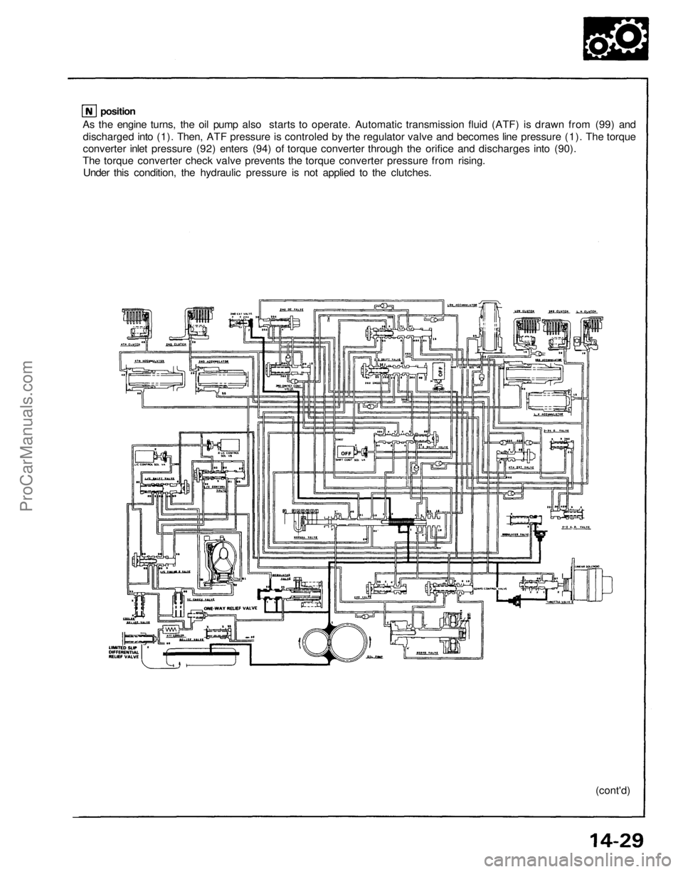
As the engine turns, the oil pump also starts to operate. Automatic transmission fluid (ATF) is drawn from (99) and
discharged into (1). Then, ATF pressure is controled by the regulator valve and becomes line pressure (1). The torque
converter inlet pressure (92) enters (94) of torque converter through the orifice and discharges into (90).
The torque converter check valve prevents the torque converter pressure from rising.
Under this condition, the hydraulic pressure is not applied to the clutches.
(cont'd)
positionProCarManuals.com
Page 1224 of 1640
Fluid Level
Checking/Changing
Checking
NOTE: Check the fluid level with the engine at nor-
mal operating temperature (the cooling fan comes
on).
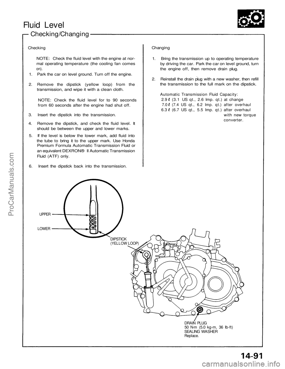
1. Park the car on level ground. Turn off the engine.
2. Remove the dipstick (yellow loop) from the
transmission, and wipe it with a clean cloth.
NOTE: Check the fluid level for to 90 seconds
from 60 seconds after the engine had shut off.
3. Insert the dipstick into the transmission.
4. Remove the dipstick, and check the fluid level. It
should be between the upper and lower marks.
5. If the level is below the lower mark, add fluid into
the tube to bring it to the upper mark. Use Honda
Premium Formula Automatic Transmission Fluid or
an equivalent DEXRON® II Automatic Transmission
Fluid (ATF) only.
6. Insert the dipstick back into the transmission.
UPPER
LOWER
DIPSTICK
(YELLOW LOOP)
DRAIN PLUG
50 N·m (5.0 kg-m, 36 Ib-ft)
SEALING WASHER
Replace.
Changing
1. Bring the transmission up to operating temperature
by driving the car. Park the car on level ground, turn
the engine off, then remove drain plug.
2. Reinstall the drain plug with a new washer, then refill
the transmission to the full mark on the dipstick.
Automatic Transmission Fluid Capacity:
2.9 (3.1 US qt., 2.6 Imp. qt.) at change
7.0 (7.4 US qt., 6.2 Imp. qt.) after overhaul
6.3 (6.7 US qt., 5.5 Imp. qt.) after overhaul
with new torque
converter.ProCarManuals.com
Page 1229 of 1640
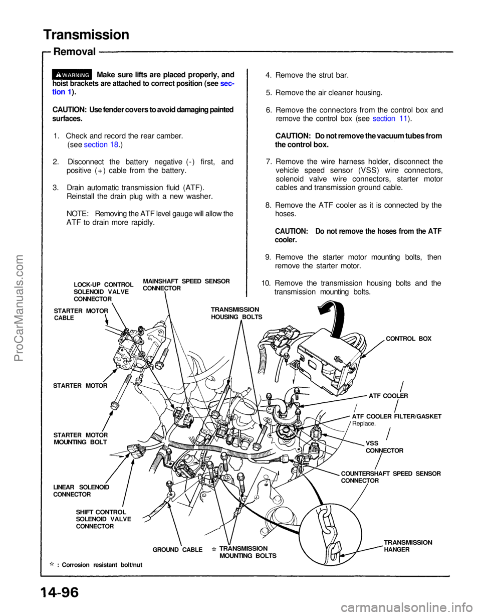
Transmission
Removal
Make sure lifts are placed properly, and
hoist brackets are attached to correct position (see sec-
tion 1).
CAUTION: Use fender covers to avoid damaging painted
surfaces.
1. Check and record the rear camber. (see section 18.)
2. Disconnect the battery negative (-) first, and positive (+) cable from the battery.
3. Drain automatic transmission fluid (ATF). Reinstall the drain plug with a new washer.
NOTE: Removing the ATF level gauge will allow the
ATF to drain more rapidly. 4. Remove the strut bar.
5. Remove the air cleaner housing.
6. Remove the connectors from the control box and remove the control box (see section 11).
CAUTION: Do not remove the vacuum tubes from
the control box.
7. Remove the wire harness holder, disconnect the vehicle speed sensor (VSS) wire connectors,
solenoid valve wire connectors, starter motor
cables and transmission ground cable.
8. Remove the ATF cooler as it is connected by the
hoses.
CAUTION: Do not remove the hoses from the ATF
cooler.
9. Remove the starter motor mounting bolts, then remove the starter motor.
10. Remove the transmission housing bolts and the transmission mounting bolts.
MAINSHAFT SPEED SENSOR
CONNECTOR
LOCK-UP CONTROL
SOLENOID VALVE
CONNECTOR
STARTER MOTOR
TRANSMISSION
HOUSING BOLTS
CONTROL BOX
STARTER MOTOR
STARTER MOTOR
MOUNTING BOLT
ATF COOLER
ATF COOLER FILTER/GASKET Replace.
VSS
CONNECTOR
COUNTERSHAFT SPEED SENSOR
CONNECTOR
LINEAR SOLENOID
CONNECTOR
SHIFT CONTROL
SOLENOID VALVE
CONNECTOR
GROUND CABLE
TRANSMISSION
MOUNTING BOLTS
TRANSMISSION
HANGER
Corrosion resistant bolt/nut
CABLEProCarManuals.com
Page 1574 of 1640
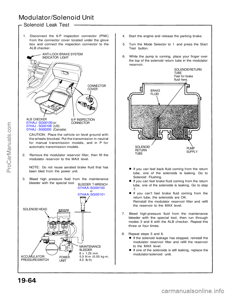
Modulator/Solenoid Unit
Solenoid Leak Test
1. Disconnect the 6-P inspection connector (PNK) from the connector cover located under the glovebox and connect the inspection connector to the
ALB checker.
ANTI-LOCK BRAKE SYSTEM
INDICATOR LIGHT
CONNECTOR
COVER
ALB CHECKER
07HAJ - SG00100 or
07HAJ - SG0010B (US)
07HAJ - SG00200 (Canada)
6-P INSPECTION
CONNECTOR
CAUTION: Place the vehicle on level ground with
the wheels blocked. Put the transmission in neutral
for manual transmission models, and in P for automatic transmission models.
2. Remove the modulator reservoir filter, then fill the modulator reservoir to the MAX level.
NOTE: Do not reuse aerated brake fluid that has
been bled from the power unit.
3. Bleed high pressure fluid from the maintenance bleeder with the special tool.
BLEEDER T-WRENCH
07HAA-SG00100
or
07HAA-SG00101
SOLENOID HEAD
MAINTENANCE
BLEEDER
8 x
1.25
mm
5.5 N·m
(0.55 kg-m,
4.0 Ib-ft)
POWER
UNIT
ACCUMULATOR/
PRESSURE SWITCH
If you can feel back fluid coming from the return
tube, one of the solenoids is leaking. Go to Solenoid Flushing.If you can feel brake fluid coming from the return
tube, one of the solenoids is leaking. Go to step
7.
If you can't feel brake fluid coming from the return tube, the solenoids are OK.
Reinstall the modulator reservoir filter and refill
the reservoir to the MAX level.
7. Bleed high-pressure fluid from the maintenance
bleeder with the special tool, then run through
modes 3 and 6 with the ALB checker. Repeat this
three or four times.
8. Repeat steps 5 and 6. If the solenoid leakage has stopped, reinstall the
modulator reservoir filter and refill the reservoir
to the MAX level. If one of the solenoids is still leaking, replace the
modulator/solenoid
unit.
SOLENOID
RETURN
TUBE
PUMP
SUPPLY
BRAKE
FLUID
SOLENOID RETURN
TUBE
Feel for brake
fluid here.
4. Start the engine and release the parking brake.
5. Turn the Mode Selector to 1 and press the Start Test button.
6. While the pump is running, place your finger over the top of the solenoid return tube in the modulator
reservoir.ProCarManuals.com
Page 1576 of 1640
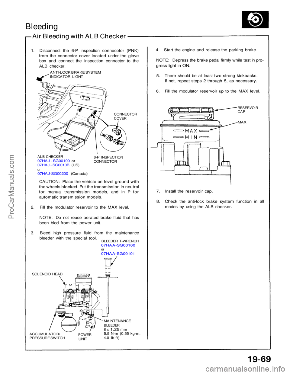
Bleeding
Air Bleeding with ALB Checker
1. Disconnect the 6-P inspection connecotor (PNK) from the connector cover located under the glovebox and connect the inspection connector to the
ALB checker.
ANTI-LOCK BRAKE SYSTEM
INDICATOR LIGHT
CONNECTOR
COVER
ALB CHECKER
07HAJ - SG00100 or
07HAJ - SG0010B (US)
or
07HAJ-SG00200 (Canada)
6-P INSPECTION
CONNECTOR
CAUTION: Place the vehicle on level ground with
the wheels blocked. Put the transmission in neutral
for manual transmission models, and in P for automatic transmission models.
2. Fill the modulator reservoir to the MAX level.
NOTE: Do not reuse aerated brake fluid that has
been bled from the power unit.
3. Bleed high pressure fluid from the maintenance bleeder with the special tool.
BLEEDER T-WRENCH
07HAA-SG00100
or
07HAA-SG00101
SOLENOID HEAD
ACCUMULATOR/
PRESSURE SWITCH
POWER
UNIT
MAINTENANCE
BLEEDER
8 x
1.25
mm
5.5 N·m
(0.55 kg-m,
4.0 Ib-ft) 7. Install the reservoir cap.
8. Check the anti-lock brake system function in all
modes by using the ALB checker.
MAX
RESERVOIR
CAP
4. Start the engine and release the parking brake.
NOTE: Depress the brake pedal firmly while test in pro-
gress light in ON.
5. There should be at least two strong kickbacks. If not, repeat steps 2 through 5, as necessary.
6. Fill the modulator reservoir up to the MAX level.ProCarManuals.com