oil ACURA NSX 1991 Service Repair Manual
[x] Cancel search | Manufacturer: ACURA, Model Year: 1991, Model line: NSX, Model: ACURA NSX 1991Pages: 1640, PDF Size: 60.48 MB
Page 9 of 1640
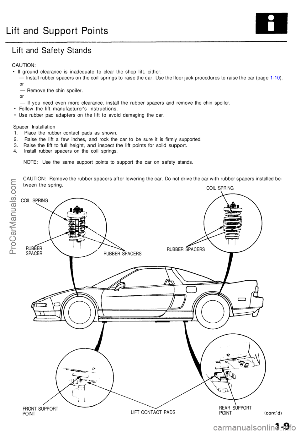
Lift an d Suppor t Point s
Lift an d Safet y Stand s
CAUTION :
• I f groun d clearanc e i s inadequat e t o clea r th e sho p lift , either :
— Instal l rubbe r spacer s o n th e coi l spring s t o rais e th e car . Us e th e floo r jac k procedure s t o rais e th e ca r (pag e 1-10 ).
o r
— Remov e th e chi n spoiler .
or
— If yo u nee d eve n mor e clearance , instal l th e rubbe r spacer s an d remov e th e chi n spoiler .
• Follo w th e lif t manufacturer' s instructions .
• Us e rubbe r pa d adapter s o n th e lif t t o avoi d damagin g th e car .
Space r Installatio n
1 . Plac e th e rubbe r contac t pad s a s shown .
2 . Rais e th e lif t a fe w inches , an d roc k th e ca r t o b e sur e i t i s firml y supported .
3. Rais e the lift to ful l height , and inspec t the lift point s for soli d support .
4. Instal l rubbe r spacer s o n th e coi l springs .
NOTE : Us e th e sam e suppor t point s t o suppor t th e ca r o n safet y stands .
CAUTION : Remov e th e rubbe r spacer s afte r lowerin g th e car . D o no t driv e th e ca r wit h rubbe r spacer s installe d be -
twee n th e spring .
COIL SPRIN G
COIL SPRIN G
RUBBE RSPACE R
FRONT SUPPOR TPOINTLIFT CONTAC T PAD SREAR SUPPOR TPOINT
RUBBE R SPACER SRUBBER SPACER S
ProCarManuals.com
Page 27 of 1640
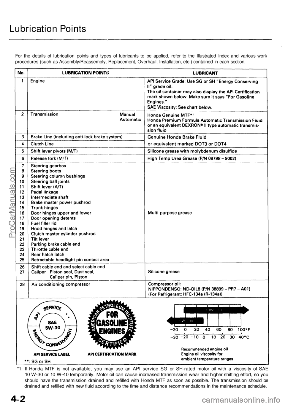
Lubrication Points
For the details of lubrication points and types of lubricants to be applied, refer to the Illustrated Index and various work
procedures (such as Assembly/Reassembly, Replacement, Overhaul, Installation, etc.) contained in each section.
*1: If Honda MTF is not available, you may use an API service SG or SH-rated motor oil with a viscosity of SAE
10 W-30 or 10 W-40 temporarily. Motor oil can cause increased transmission wear and higher shifting effort, so you
should have the transmission drained and refilled with Honda MTF as soon as possible. The transmission should be
drained and refilled with new fluid according to the time and distance recommendations in the maintenance schedule.ProCarManuals.com
Page 33 of 1640
Maintenance
Transmissio n Oi l
NOTE : Chec k th e oi l a t norma l operatin g temperatur e
(the coolin g fa n come s on) , engin e OFF , an d th e ca r o n
leve l ground .
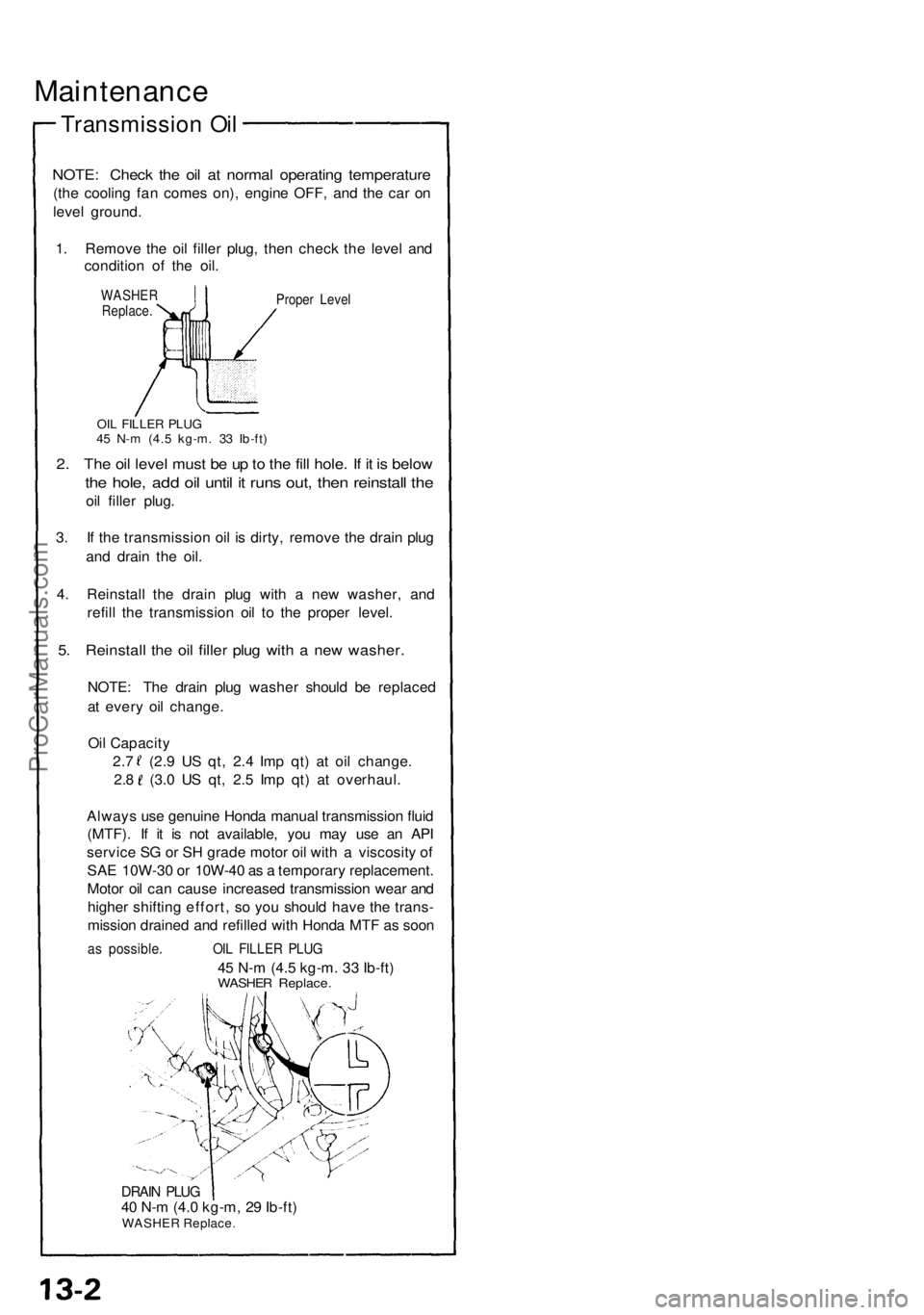
1 . Remov e th e oi l fille r plug , the n chec k th e leve l an d
conditio n o f th e oil .
WASHE RReplace .Proper Leve l
OIL FILLE R PLU G45 N- m (4. 5 kg-m . 3 3 Ib-ft )
2. Th e oi l leve l mus t b e u p to th e fil l hole . I f i t i s belo w
the hole , ad d oi l unti l i t run s out , the n reinstal l th e
oil fille r plug .
3 . I f th e transmissio n oi l i s dirty , remov e th e drai n plu g
an d drai n th e oil .
4 . Reinstal l th e drai n plu g wit h a ne w washer , an d
refil l th e transmissio n oi l t o th e prope r level .
5. Reinstal l th e oi l fille r plu g wit h a ne w washer .
NOTE: Th e drai n plu g washe r shoul d b e replace d
a t ever y oi l change .
Oi l Capacit y
2. 7 ( 2.9 U S qt , 2. 4 Im p qt ) a t oi l change .
2.8 (3. 0 U S qt , 2. 5 Im p qt ) a t overhaul .
Alway s us e genuin e Hond a manua l transmissio n flui d
(MTF) . I f i t i s no t available , yo u ma y us e a n AP I
servic e S G o r S H grad e moto r oi l wit h a viscosit y o f
SA E 10W-3 0 o r 10W-4 0 a s a temporar y replacement .
Moto r oi l ca n caus e increase d transmissio n wea r an d
highe r shiftin g effort , s o yo u shoul d hav e th e trans -
missio n draine d an d refille d wit h Hond a MT F a s soo n
as possible . OIL FILLE R PLU G
45 N- m (4. 5 kg-m . 3 3 Ib-ft )WASHE R Replace .
DRAIN PLU G40 N- m (4. 0 kg-m , 2 9 Ib-ft )WASHE R Replac e
ProCarManuals.com
Page 41 of 1640
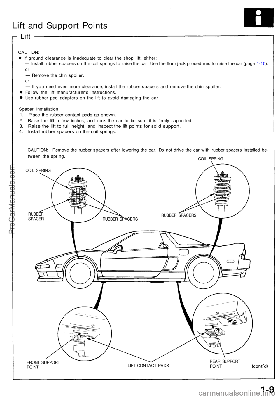
Lift an d Suppor t Point s
Lift
CAUTION :
I f groun d clearanc e i s inadequat e t o clea r th e sho p lift , either :
— Instal l rubbe r spacer s o n th e coi l spring s t o rais e th e car . Us e th e floo r jac k procedure s t o rais e th e ca r (pag e 1-10 ).
o r
— Remov e th e chi n spoiler .
or
— If yo u nee d eve n mor e clearance , instal l th e rubbe r spacer s an d remov e th e chi n spoiler .
Follo w th e lif t manufacturer' s instructions .
Us e rubbe r pa d adapter s o n th e lif t t o avoi d damagin g th e car .
Space r Installatio n
1. Plac e th e rubbe r contac t pad s a s shown .
2. Rais e th e lif t a fe w inches, and roc k th e ca r t o b e sur e i t i s firml y supported .
3. Rais e th e lif t t o ful l height , an d inspec t th e lif t point s fo r soli d support .
4. Instal l rubbe r spacer s o n th e coi l springs .
CAUTION : Remov e th e rubbe r spacer s afte r lowerin g th e car . D o no t driv e th e ca r wit h rubbe r spacer s installe d be -
twee n th e spring .
COIL SPRIN G
COIL SPRIN G
RUBBE RSPACER
FRONT SUPPOR TPOINTLIFT CONTAC T PAD SREAR SUPPOR TPOINT
RUBBE R SPACER SRUBBER SPACER S
ProCarManuals.com
Page 72 of 1640
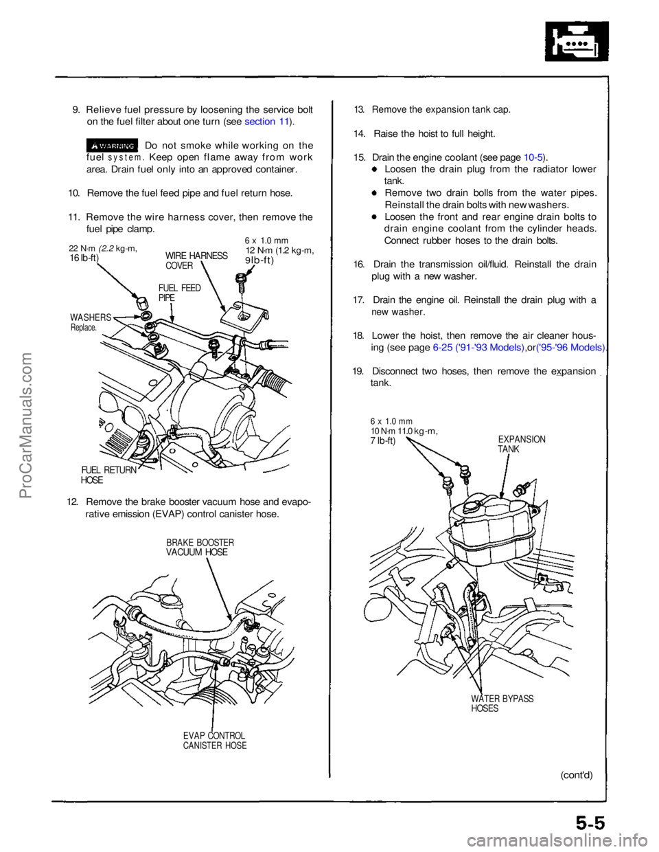
9. Relieve fuel pressure by loosening the service bolt
on the fuel filter about one turn (see section 11).
Do not smoke while working on the
fuel
system.
Keep open flame away from work
area. Drain fuel only into an approved container.
10. Remove the fuel feed pipe and fuel return hose.
11. Remove the wire harness cover, then remove the fuel pipe clamp.
22 N·m
(2.2 kg-m,
16 Ib-ft)
WIRE HARNESS
COVER
6 x 1.0 mm
12 N·m
(1.2 kg-m,
9 lb-ft)
FUEL FEED
PIPE
WASHERS
Replace.
FUEL RETURN
HOSE
12. Remove the brake booster vacuum hose and evapo- rative emission (EVAP) control canister hose.
BRAKE BOOSTER
VACUUM HOSE
EVAP CONTROL
CANISTER HOSE
13. Remove the expansion tank cap.
14. Raise the hoist to full height.
15. Drain the engine coolant (see page
10-5).
Loosen the drain plug from the radiator lower
tank. Remove two drain bolls from the water pipes.
Reinstall the drain bolts with new washers.
Loosen the front and rear engine drain bolts to
drain engine coolant from the cylinder heads.
Connect rubber hoses to the drain bolts.
16. Drain the transmission oil/fluid. Reinstall the drain plug with a new washer.
17. Drain the engine oil. Reinstall the drain plug with a
new washer.
18. Lower the hoist, then remove the air cleaner hous-
ing (see page 6-25 ('91-'93 Mode ls),or('95-'96 Models).
19. Disconnect two hoses, then remove the expansion
tank.
6 x 1.0 mm
10 N·m
11.0 kg-m,
7 lb-ft)
EXPANSION
TANK
WATER BYPASS
HOSES
(cont'd)ProCarManuals.com
Page 77 of 1640
Engine Removal/Installatio n
Removal
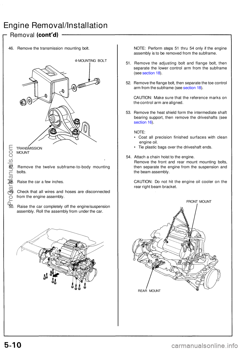
46. Remov e th e transmissio n mountin g bolt .
MOUNTIN G BOL T
TRANSMISSIO NMOUNT
47. Remov e th e twelv e subframe-to-bod y mountin g
bolts.
48. Rais e th e ca r a fe w inches .
49. Chec k tha t al l wire s an d hose s ar e disconnecte d
from th e engin e assembly .
50 . Rais e th e ca r completel y of f th e engine/suspensio n
assembly . Rol l th e assembl y fro m unde r th e car . NOTE
: Perfor m step s 5 1 thr u 5 4 onl y i f th e engin e
assembl y is t o b e remove d fro m th e subframe .
51 . Remov e th e adjustin g bol t an d flang e bolt , the n
separat e th e lowe r contro l ar m fro m th e subfram e
(se e sectio n 18 ).
52 . Remov e th e flang e bolt , the n separat e th e to e contro l
ar m fro m th e subfram e (se e sectio n 18 ).
CAUTION : Mak e sur e tha t th e referenc e mark s o n
th e contro l ar m ar e aligned .
53 . Remov e th e hea t shiel d for m th e intermediat e shaf t
bearin g support , the n remov e th e driveshaft s (se e
sectio n 16 ).
NOTE :
• Coa t al l precisio n finishe d surface s wit h clea n
engin e oil .
• Ti e plasti c bag s ove r th e driveshaf t ends .
54 . Attac h a chai n hois t t o th e engine .
Remov e th e fron t an d rea r moun t mountin g bolts ,
the n separat e th e engine from th e suspensio n an d
th e bea m assembly .
CAUTION : D o no t hi t th e engin e oi l coole r o n th e
rea r righ t bea m bracket .
FRONT MOUN T
REAR MOUN T
ProCarManuals.com
Page 80 of 1640
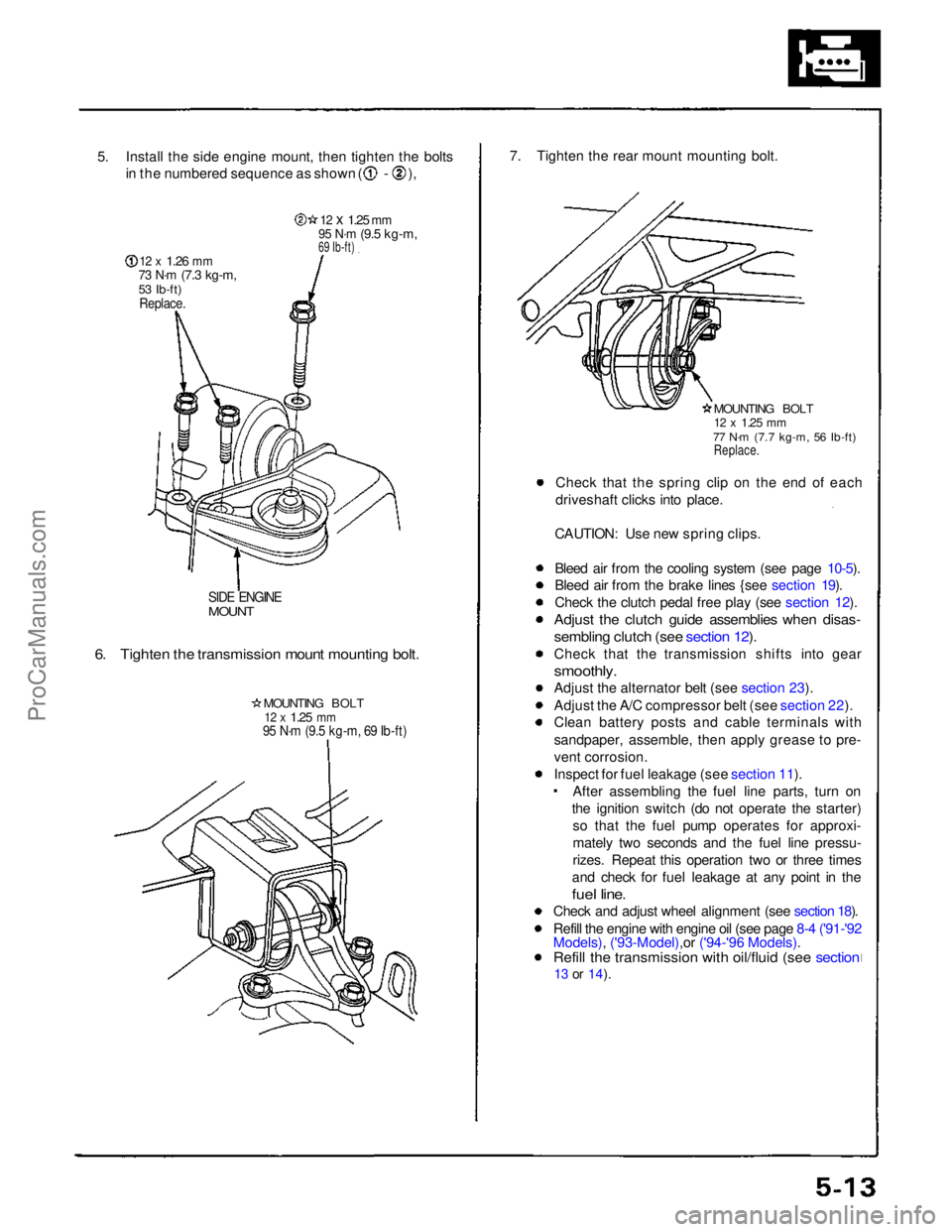
5. Install the side engine mount, then tighten the bolts
in the numbered sequence as shown ( - ),
12 x
1.26
mm
73 N·m
(7.3 kg-m,
53 Ib-ft)
Replace.
12 x
1.25
mm
95 N·m
(9.5 kg-m,
69 Ib-ft)
SIDE ENGINE
MOUNT
6. Tighten the transmission mount mounting bolt.
MOUNTING BOLT
12 x
1.25
mm
95 N·m (9.5 kg-m, 69 Ib-ft)
7. Tighten the rear mount mounting bolt.
MOUNTING BOLT
12 x
1.25
mm
77 N·m (7.7 kg-m, 56 Ib-ft)
Replace.
Check that the spring clip on the end of each
driveshaft clicks into place.
CAUTION: Use new spring clips.
Bleed air from the cooling system (see page 10-5).
Bleed air from the brake lines {see section 19).
Check the clutch pedal free play (see section 12).
Adjust the clutch guide assemblies when disas-
sembling clutch (see section 12).
Check that the transmission shifts into gear
smoothly.
Adjust the alternator belt (see section 23).
Adjust the A/C compressor belt (see section 22).
Clean battery posts and cable terminals with
sandpaper, assemble, then apply grease to pre-
vent corrosion.
Inspect for fuel leakage (see section 11). After assembling the fuel line parts, turn on
the ignition switch (do not operate the starter) so that the fuel pump operates for approxi-
mately two seconds and the fuel line pressu-
rizes. Repeat this operation two or three times
and check for fuel leakage at any point in the
fuel line.
Check and adjust wheel alignment (see section 18).
Refill the engine with engine oil (see page 8-4 ('91-'92
Models), ('93-Model),or ('94-'96 Models).
Refill the transmission with oil/fluid (see section
13 or
14).ProCarManuals.com
Page 82 of 1640
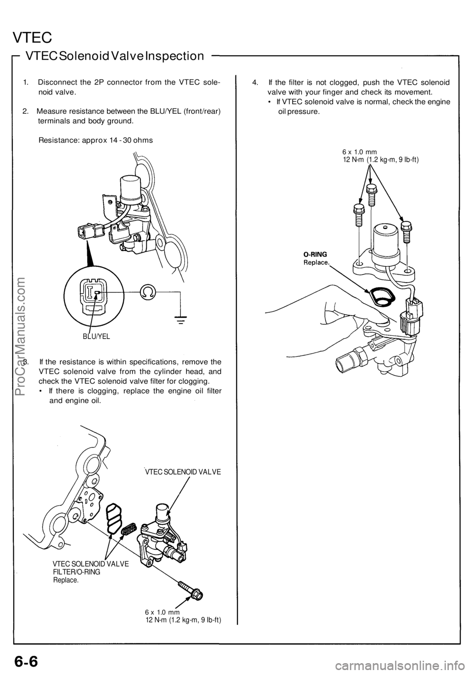
VTEC
VTEC Solenoi d Valv e Inspectio n
1. Disconnec t th e 2 P connecto r fro m th e VTE C sole -
noi d valve .
2 . Measur e resistanc e betwee n th e BLU/YE L (front/rear )
terminal s an d bod y ground .
Resistance : appro x 1 4 - 3 0 ohm s
BLU/YE L
3. I f th e resistanc e i s withi n specifications , remov e th e
VTE C solenoi d valv e fro m th e cylinde r head , an d
chec k th e VTE C solenoi d valv e filte r fo r clogging .
• I f ther e i s clogging , replac e th e engin e oi l filte r
an d engin e oil .
VTE C SOLENOI D VALV E
VTE C SOLENOI D VALV E
FILTER/O-RIN G
Replace.
6 x 1. 0 m m12 N- m (1. 2 kg-m , 9 Ib-ft )
4. I f th e filte r i s no t clogged , pus h th e VTE C solenoi d
valv e wit h you r finge r an d chec k it s movement .
• I f VTE C solenoi d valv e is normal , chec k th e engin e
oi l pressure .
6 x 1. 0 m m12 N- m (1. 2 kg-m , 9 Ib-ft )
ProCarManuals.com
Page 83 of 1640
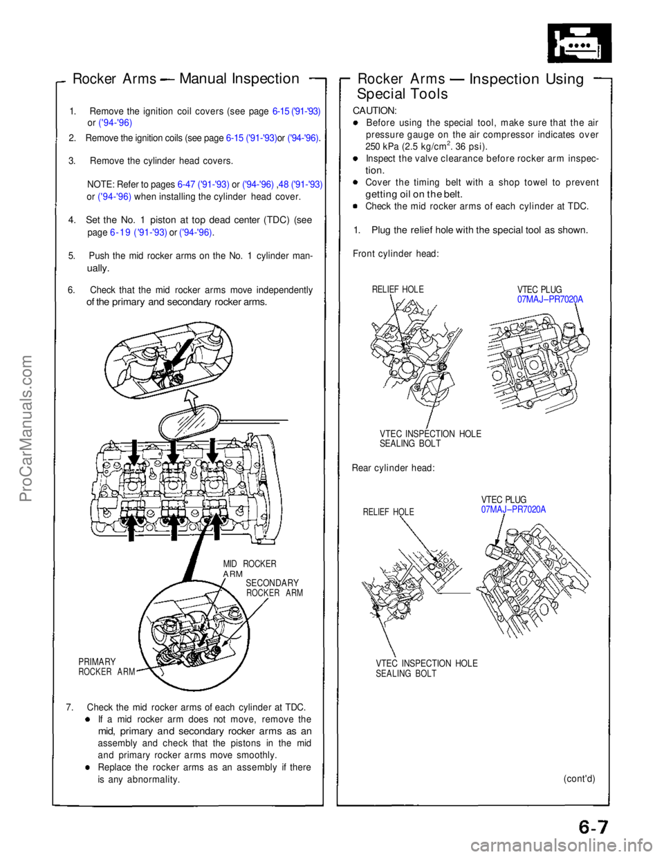
Rocker Arms
Manual Inspection
1. Remove the ignition coil covers (see page 6-15 ('91-'93) or ('94-'96)
2. Remove the ignition coils (see page 6-15 ('91-'93)or ('94-'96).
3. Remove the cylinder head covers.
NOTE: Refer to pages 6-47 ('91-'93)
or ('94-'96) ,48 ('91-'93)
or ('94-'96) when installing the cylinder head cover.
4. Set the No. 1 piston at top dead center (TDC) (see
page 6-19 ('91-'93)
or ('94-'96).
5. Push the mid rocker arms on the No. 1 cylinder man-
ually.
6. Check that the mid rocker arms move independently
of the primary and secondary rocker arms.
MID ROCKER
ARM
SECONDARY
ROCKER ARM
PRIMARY
ROCKER ARM
7. Check the mid rocker arms of each cylinder at TDC. If a mid rocker arm does not move, remove the
mid, primary and secondary rocker arms as an
assembly and check that the pistons in the mid
and primary rocker arms move smoothly.
Replace the rocker arms as an assembly if there
is any abnormality. Rocker Arms
Inspection Using
Special Tools
CAUTION:
Before using the special tool, make sure that the air
pressure gauge on the air compressor indicates over
250 kPa (2.5 kg/cm2. 36 psi). Inspect the valve clearance before rocker arm inspec-
tion.
Cover the timing belt with a shop towel to prevent
getting oil on the belt.
Check the mid rocker arms of each cylinder at TDC.
1. Plug the relief hole with the special tool as shown.
Front cylinder head:
RELIEF HOLE
VTEC PLUG
07MAJ–PR7020A
VTEC INSPECTION HOLE
SEALING BOLT
Rear cylinder head:
RELIEF HOLE
VTEC PLUG
07MAJ–PR7020A
VTEC INSPECTION HOLE
SEALING BOLT
(cont'd)ProCarManuals.com
Page 88 of 1640
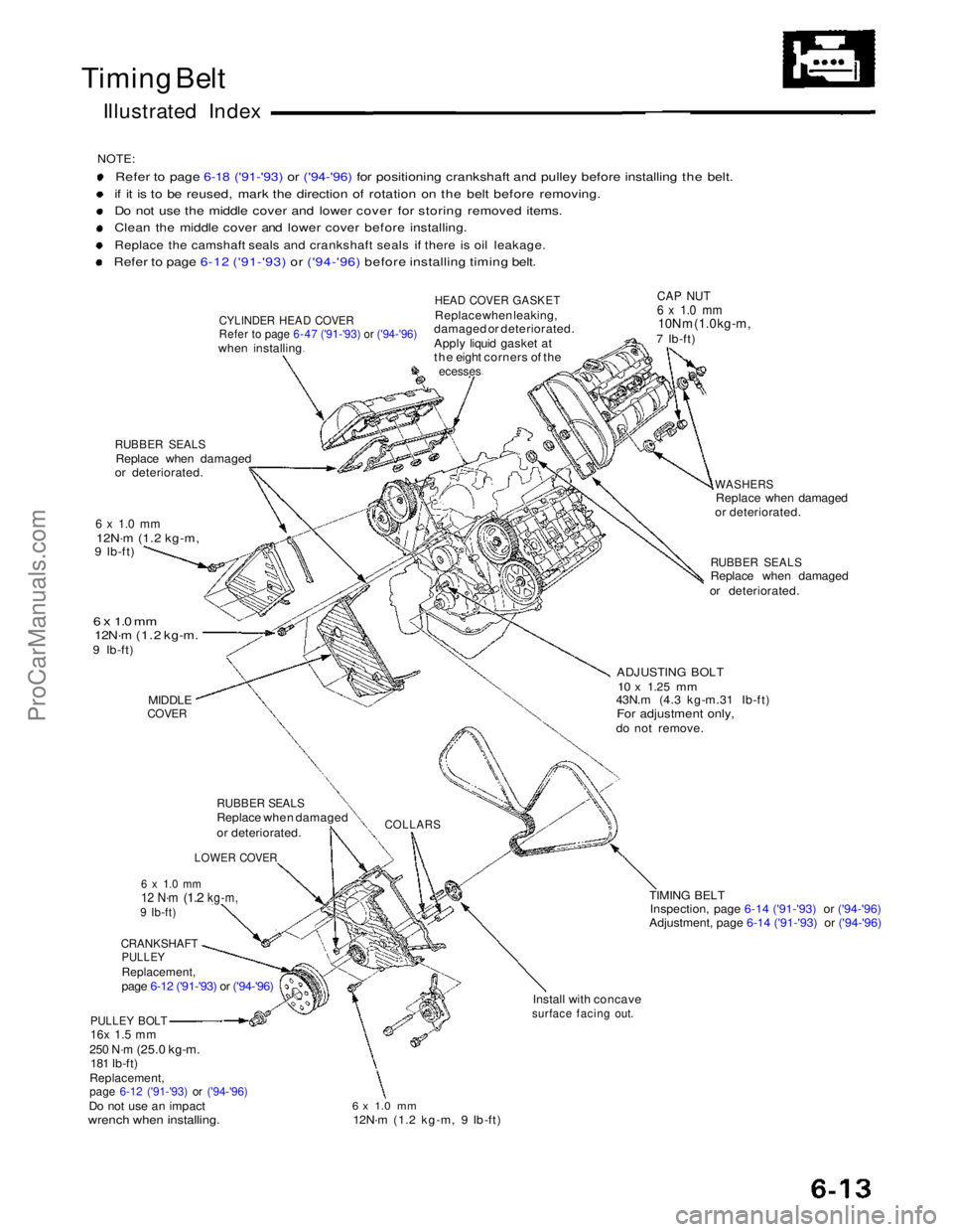
Timing Belt
Illustrated Index
NOTE:
Refer to page 6-18 ('91-'93) or ('94-'96) for positioning crankshaft and pulley before installing the belt.
if it is to be reused, mark the direction of rotation on the belt before removing.
Do not use the middle cover and lower cover for storing removed items.
Clean the middle cover and lower cover before installing.
Replace the camshaft seals and crankshaft seals if there is oil leakage.
Refer to page 6-12 ('91-'93) or ('94-'96) before installing timing belt.
CYLINDER HEAD COVER
Refer to page 6-47 ('91-'93) or ('94-'96)
when installing
RUBBER SEALS
Replace when damaged
or deteriorated.
6 x 1.0 mm
12N·m (1.2 kg-m,
9 Ib-ft)
6 x 1.0 mm
12N·m (1.2 kg-m.
9 Ib-ft)
MIDDLE
COVER
RUBBER SEALS
Replace when damaged
or deteriorated.
LOWER COVER
6 x 1.0 mm
12 N·m
(1.2
kg-m,
9 Ib-ft)
CRANKSHAFT
PULLEY
Replacement,
page 6-12 ('91-'93) or ('94-'96)
PULLEY BOLT
16x 1.5 mm
250 N·m
(25.0 kg-m. 181 Ib-ft)
Replacement,
page 6-12 ('91-'93)
or ('94-'96)
Do not use an impact
wrench when installing.
HEAD COVER GASKET
Replace when leaking,
damaged or deteriorated.
Apply liquid gasket at
the eight corners of the
ecesses
CAP NUT
6 x 1.0 mm
10N m (1.0 kg-m,
7 Ib-ft)
WASHERS
Replace when damaged
or deteriorated.
RUBBER SEALS
Replace when damaged
or deteriorated.
ADJUSTING BOLT
10 x
1.25
mm
43N.m (4.3 kg-m.31 Ib-ft)
For adjustment only,
do not remove.
COLLARS
TIMING BELTInspection, page 6-14 ('91-'93) or ('94-'96)
Adjustment, page 6-14 ('91-'93) or ('94-'96)
Install with concave
surface facing out.
6 x 1.0 mm
12N·m (1.2 kg-m, 9 Ib-ft)ProCarManuals.com