fuel cap ACURA NSX 1991 Service Repair Manual
[x] Cancel search | Manufacturer: ACURA, Model Year: 1991, Model line: NSX, Model: ACURA NSX 1991Pages: 1640, PDF Size: 60.48 MB
Page 72 of 1640
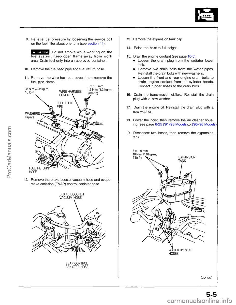
9. Relieve fuel pressure by loosening the service bolt
on the fuel filter about one turn (see section 11).
Do not smoke while working on the
fuel
system.
Keep open flame away from work
area. Drain fuel only into an approved container.
10. Remove the fuel feed pipe and fuel return hose.
11. Remove the wire harness cover, then remove the fuel pipe clamp.
22 N·m
(2.2 kg-m,
16 Ib-ft)
WIRE HARNESS
COVER
6 x 1.0 mm
12 N·m
(1.2 kg-m,
9 lb-ft)
FUEL FEED
PIPE
WASHERS
Replace.
FUEL RETURN
HOSE
12. Remove the brake booster vacuum hose and evapo- rative emission (EVAP) control canister hose.
BRAKE BOOSTER
VACUUM HOSE
EVAP CONTROL
CANISTER HOSE
13. Remove the expansion tank cap.
14. Raise the hoist to full height.
15. Drain the engine coolant (see page
10-5).
Loosen the drain plug from the radiator lower
tank. Remove two drain bolls from the water pipes.
Reinstall the drain bolts with new washers.
Loosen the front and rear engine drain bolts to
drain engine coolant from the cylinder heads.
Connect rubber hoses to the drain bolts.
16. Drain the transmission oil/fluid. Reinstall the drain plug with a new washer.
17. Drain the engine oil. Reinstall the drain plug with a
new washer.
18. Lower the hoist, then remove the air cleaner hous-
ing (see page 6-25 ('91-'93 Mode ls),or('95-'96 Models).
19. Disconnect two hoses, then remove the expansion
tank.
6 x 1.0 mm
10 N·m
11.0 kg-m,
7 lb-ft)
EXPANSION
TANK
WATER BYPASS
HOSES
(cont'd)ProCarManuals.com
Page 251 of 1640
Fuel Suppl y Syste m
Fuel Pressur e
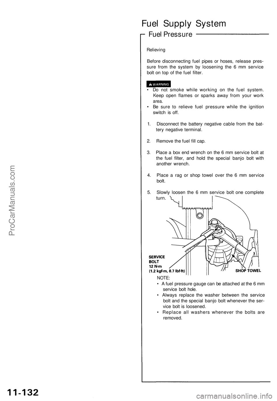
Relieving
Before disconnectin g fue l pipe s o r hoses , releas e pres -
sur e fro m th e syste m b y loosenin g th e 6 m m servic e
bol t o n to p o f th e fue l filter .
• D o no t smok e whil e workin g o n th e fue l system .
Kee p ope n flame s o r spark s awa y fro m you r wor k
area.
• B e sur e t o reliev e fue l pressur e whil e th e ignitio n
switc h i s off .
1 . Disconnec t th e batter y negativ e cabl e fro m th e bat -
ter y negativ e terminal .
2 . Remov e th e fue l fil l cap .
3 . Plac e a bo x en d wrenc h o n th e 6 m m servic e bol t a t
th e fue l filter , an d hol d th e specia l banj o bol t wit h
anothe r wrench .
4 . Plac e a ra g o r sho p towe l ove r th e 6 m m servic e
bolt.
5. Slowl y loose n th e 6 m m servic e bol t on e complet e
turn.
NOTE :
• A fue l pressur e gaug e ca n b e attache d a t th e 6 m m
servic e bol t hole .
• Alway s replac e th e washe r betwee n th e servic e
bol t an d th e specia l banj o bol t wheneve r th e ser -
vic e bol t i s loosened .
• Replac e al l washer s wheneve r th e bolt s ar e
removed .
ProCarManuals.com
Page 280 of 1640
Evaporative Emission (EVAP) Controls
Description
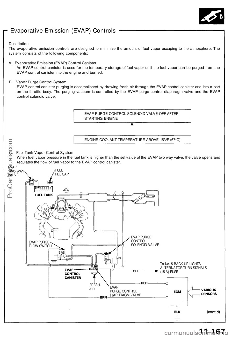
The evaporative emission controls are designed to minimize the amount of fuel vapor escaping to the atmosphere. The
system consists of the following components:
A. Evaporative Emission (EVAP) Control Canister
An EVAP control canister is used for the temporary storage of fuel vapor until the fuel vapor can be purged from the
EVAP control canister into the engine and burned.
B. Vapor Purge Control System
EVAP control canister purging is accomplished by drawing fresh air through the EVAP control canister and into a port
on the throttle body. The purging vacuum is controlled by the EVAP purge control diaphragm valve and the EVAP
control solenoid valve.
EVAP PURGE CONTROL SOLENOID VALVE OFF AFTER
STARTING ENGINE
ENGINE COOLANT TEMPERATURE ABOVE 153°F (67°C)
To No. 5 BACK-UP LIGHTS
ALTERNATOR TURN SIGNALS
(15 A) FUSE
FRESH
AIR
EVAP
PURGE CONTROL
DIAPHRAGM VALVE
EVAP PURGE
CONTROL
SOLENOID VALVE
EVAP PURGE
FLOW SWITCH
C. Fuel Tank Vapor Control System
When fuel vapor pressure in the fuel tank is higher than the set value of the EVAP two way valve, the valve opens and
regulates the flow of fuel vapor to the EVAP control canister.
EVAP
TWO WAY
VALVE
FUEL
FILL CAPProCarManuals.com
Page 966 of 1640
Engine Oil
Replacement
CAUTION: Remove the drain plug carefully while the en-
gine is hot, the hot oil may cause scalding.
1. Warm up the engine.
2. Drain the engine oil.
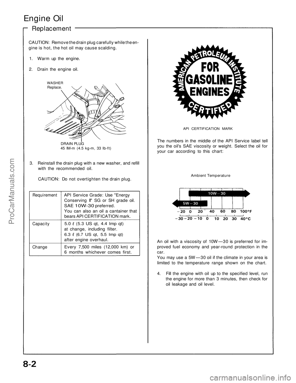
WASHER
Replace.
DRAIN PLUG
45 IM-m (4.5 kg-m, 33 Ib-ft)
3. Reinstall the drain plug with a new washer, and refill
with the recommended oil.
CAUTION: Do not overtighten the drain plug.
Requirement
API Service Grade: Use "Energy
Conserving II" SG or SH grade oil.
SAE
10W-30
preferred.
You can also an oil a cantainer that
bears API CERTIFICATION mark.
Capacity
5.0
(5.3
US qt, 4.4 Imp qt)
at change, including filter.
6.3
(6.7
US qt, 5.5 Imp qt)
after engine overhaul.
Change
Every 7,500 miles (12,000 km) or
6 months whichever comes first.
API CERTIFICATION MARK
The numbers in the middle of the API Service label tell
you the oil's SAE viscosity or weight. Select the oil for
your car according to this chart:
Ambient Temperature
An oil with a viscosity of 10W —30 is preferred for im-
proved fuel economy and year-round protection in the
car.
You may use a 5W —30 oil if the climate in your area is
limited to the temperature range shown on the chart.
4. Fill the engine with oil up to the specified level, run
the engine for more than 3 minutes, then check for
oil leakage and oil level.ProCarManuals.com
Page 998 of 1640
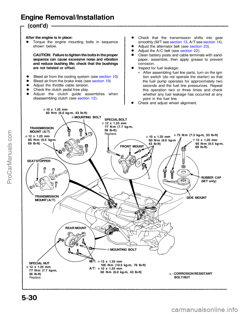
Engine Removal/Installation
(cont'd)
Torque the engine mounting bolts in sequenceshown below.
CAUTION: Failure to tighten the bolts in the proper
sequence can cause excessive noise and vibration
and reduce bushing life; check that the bushings
are not twisted or offset.
Bleed air from the cooling system (see section 10)
Bleed air from the brake lines (see section 19)
Adjust the throttle cable tension.
Check the clutch pedal free play.
Adjust the clutch guide assemblies when
disassembling clutch (see section 12). Check that the transmission shifts into gear
smoothly (M/T see section 13, A/T see section 14).
Adjust the alternator belt (see section 23).
Adjust the A/C belt (see section 22).
Clean battery posts and cable terminals with sand-
paper, assemble, then apply grease to prevent
corrosion.
Inspect for fuel leakage:
• After assembling fuel line parts, turn on the igni- tion switch (do not operate the starter) so that
the fuel pump operates for approximately two seconds and the fuel line pressurizes. Repeat
this operation two or three times and check whether any fuel leakage has occurred at any
point in the fuel line.
Check and adjust wheel alignment.
10 x
1.25
mm
60 N .
m (6.0 kg-m, 43 Ib-ft)
MOUNTING BOLT SPECIAL BOLT
12 x
1.25
mm
77 N .
m
(7.7 kg-m,
56 Ib-ft)
Replace.
10 x
1.25
mm
60 N .
m
(6.0 kg-m
43 Ib-ft) 73 N.m (7.3 kg-m, 53 Ib-ft)
12 x
1.25
mm
95 N .
m
(9.5 kg-m,
69 Ib-ft)
RUBBER CAP
(M/T only)
SIDE MOUNT
: CORROSION RESISTANT
BOLT/NUT
12 x
1.25
mm
105 N .
m (10.5 kg-m, 76 Ib-ft)
10 x
1.25
mm
60 N .
m (6.0 kg-m, 43 Ib-ft) MOUNTING BOLT FRONT MOUNT
TRANSMISSION
MOUNT (A/T)
12 x
1.25
mm
95 N .
m
(9.5 kg-m,
69 Ib-ft)
SEAT STOPPER
TRANSMISSION
MOUNT (A/T)
REAR MOUNT
SPECIAL NUT
12 x
1.25
mm
77 N .
m
(7.7 kg-m,
56 Ib-ft)
Replace.
M/T:
A/T:
After the engine is in place:ProCarManuals.com
Page 1050 of 1640
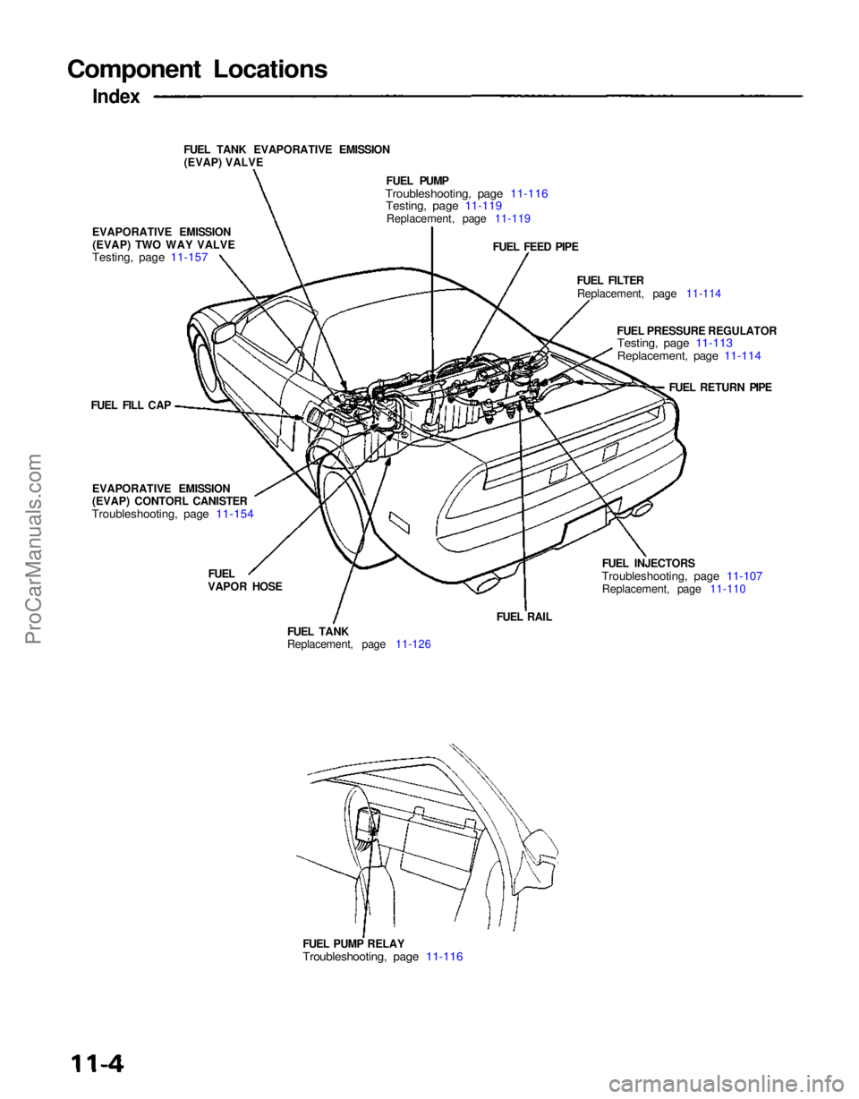
Component Locations
Index
FUEL TANK EVAPORATIVE EMISSION(EVAP) VALVE
EVAPORATIVE EMISSION (EVAP) TWO WAY VALVE
Testing, page 11-157
FUEL PUMP
Troubleshooting, page 11-116
Testing, page 11-119
Replacement, page 11-119
FUEL FEED PIPE
FUEL FILTERReplacement, page 11-114
FUEL PRESSURE REGULATOR
Testing, page 11-113
Replacement, page 11-114
FUEL RETURN PIPE
FUEL INJECTORS
Troubleshooting, page 11-107
Replacement, page 11-110
FUEL PUMP RELAY
Troubleshooting, page 11-116
FUEL RAIL
FUEL TANK
Replacement, page 11-126
FUEL
VAPOR HOSE
EVAPORATIVE EMISSION
(EVAP) CONTORL CANISTER
Troubleshooting, page 11-154
FUEL FILL CAPProCarManuals.com
Page 1109 of 1640
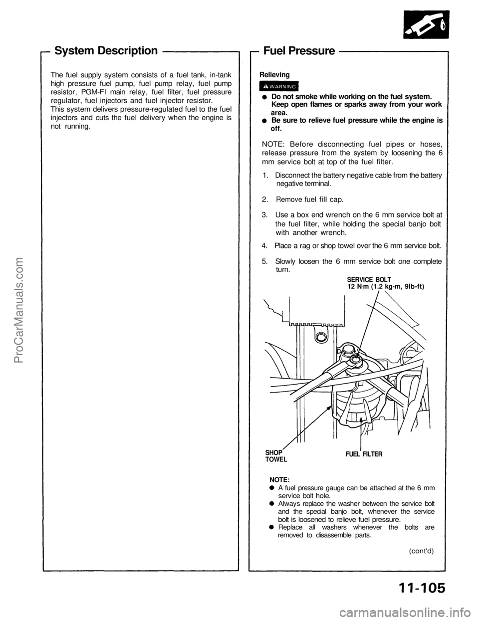
System Description
The fuel supply system consists of a fuel tank, in-tank high pressure fuel pump, fuel pump relay, fuel pump
resistor, PGM-FI main relay, fuel filter, fuel pressureregulator, fuel injectors and fuel injector resistor.
This system delivers pressure-regulated fuel to the fuel injectors and cuts the fuel delivery when the engine is
not running. Fuel Pressure
Relieving
Do not smoke while working on the fuel system.
Keep open flames or sparks away from your work
area.
Be sure to relieve fuel pressure while the engine is
off.
NOTE: Before disconnecting fuel pipes or hoses,
release pressure from the system by loosening the 6
mm service bolt at top of the fuel filter. 1. Disconnect the battery negative cable from the battery negative terminal.
2.
Remove
fuel
fill
cap.
3. Use a box end wrench on the 6 mm service bolt at the fuel filter, while holding the special banjo boltwith another wrench.
4. Place a rag or shop towel over the 6 mm service bolt.
5. Slowly loosen the 6 mm service bolt one complete turn.
SERVICE BOLT
12 N .
m (1.2 kg-m, 9lb-ft)
SHOP
TOWEL
FUEL FILTER
NOTE:
A fuel pressure gauge can be attached at the 6 mm
service bolt hole.
Always replace the washer between the service bolt
and the special banjo bolt, whenever the service
bolt is loosened to relieve fuel pressure.
Replace all washers whenever the bolts are
removed to disassemble parts.
(cont'd)ProCarManuals.com
Page 1118 of 1640
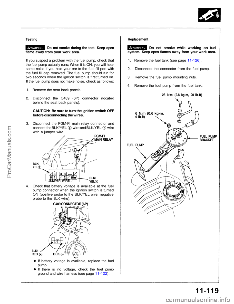
Testing
Do not smoke during the test. Keep open
If you suspect a problem with the fuel pump, check that
the fuel pump actually runs; When it is ON, you will hear some noise if you hold your ear to the fuel fill port with
the fuel fill cap removed. The fuel pump should run for
two seconds when the ignition switch is first turned on. If the fuel pump does not make noise, check as follows:
1. Remove the seat back panels.
2. Disconnect the C489 (6P) connector (located behind the seat back panels).
CAUTION: Be sure to turn the ignition switch OFF
before disconnecting the wires.
3. Disconnect the PGM-FI main relay connector and connect the BLK/YEL wire and BLK/YEL wire
with a jumper wire.
1. Remove the fuel tank (see page 11-126).
2. Disconnect the connector from the fuel pump.
3. Remove the fuel pump mounting nuts.
4. Remove the fuel pump from the fuel tank.
If battery voltage is available, replace the fuel
pump.
If there is no voltage, check the fuel pump
ground and wire harness (see page 11-122).
4. Check that battery voltage is available at the fuel
pump connector when the ignition switch is turned
ON (positive probe to the BLK/YEL wire, negative
probe to the BLK wire).
C489 CONNECTOR (6P)
BLK/
RED (+)
BLK (-)
JUMPER WIRE
flame away from your work area.
Replacement
Do not smoke while working on fuel
system. Keep open flames away from your work area.
28 N.
m (2.8 kg-m, 20 Ib-ft)
6 N.m
(0.6 kg-m,
4 Ib-ft)
FUEL PUMP
BRACKET
FUEL PUMP
PGM-FI
MAIN RELAY
BLK/
YEL
BLK/
YELProCarManuals.com
Page 1142 of 1640
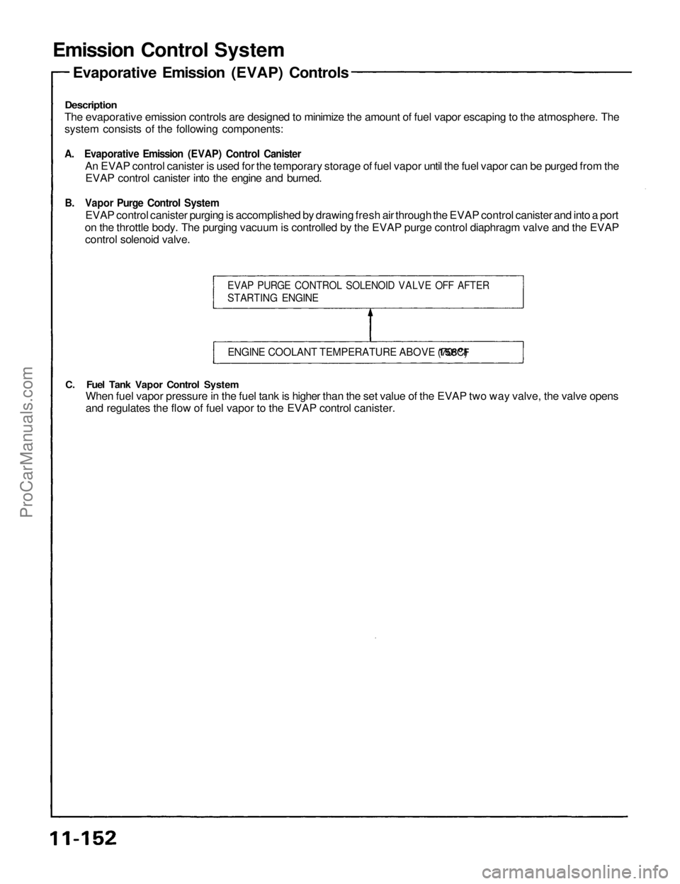
Emission Control System
Description
The evaporative emission controls are designed to minimize the amount of fuel vapor escaping to the atmosphere. The
system consists of the following components:
A. Evaporative Emission (EVAP) Control Canister
An EVAP control canister is used for the temporary storage of fuel vapor until the fuel vapor can be purged from the
EVAP control canister into the engine and burned.
B. Vapor Purge Control System
EVAP control canister purging is accomplished by drawing fresh air through the EVAP control canister and into a port
on the throttle body. The purging vacuum is controlled by the EVAP purge control diaphragm valve and the EVAP
control solenoid valve.
C. Fuel Tank Vapor Control System
When fuel vapor pressure in the fuel tank is higher than the set value of the EVAP two way valve, the valve opens
and regulates the flow of fuel vapor to the EVAP control canister.
EVAP PURGE CONTROL SOLENOID VALVE OFF AFTER
STARTING ENGINE
ENGINE COOLANT TEMPERATURE ABOVE
158°F
(70°C)
Evaporative Emission (EVAP) ControlsProCarManuals.com
Page 1143 of 1640
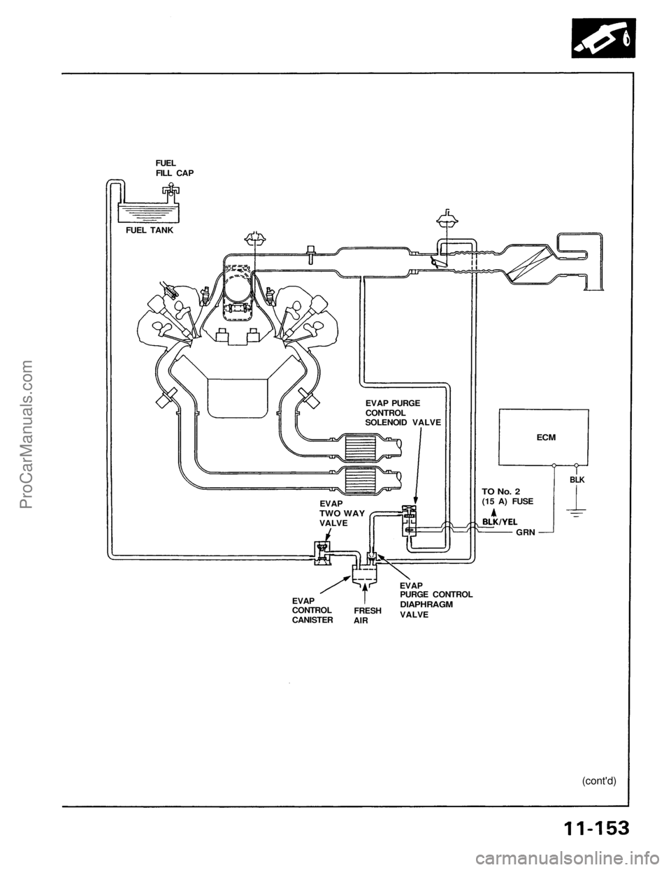
FUEL
FILL CAP
FUEL TANK
EVAP
CONTROL
CANISTER
FRESH
AIR
EVAP
PURGE CONTROL
DIAPHRAGM
VALVE
(cont'd)
BLK
ECM
TO No. 2
(15 A) FUSE
GRN
EVAP PURGE
CONTROL
SOLENOID VALVE
EVAP
TWO WAY
VALVEProCarManuals.com