fuel filter ACURA NSX 1991 Service Repair Manual
[x] Cancel search | Manufacturer: ACURA, Model Year: 1991, Model line: NSX, Model: ACURA NSX 1991Pages: 1640, PDF Size: 60.48 MB
Page 72 of 1640
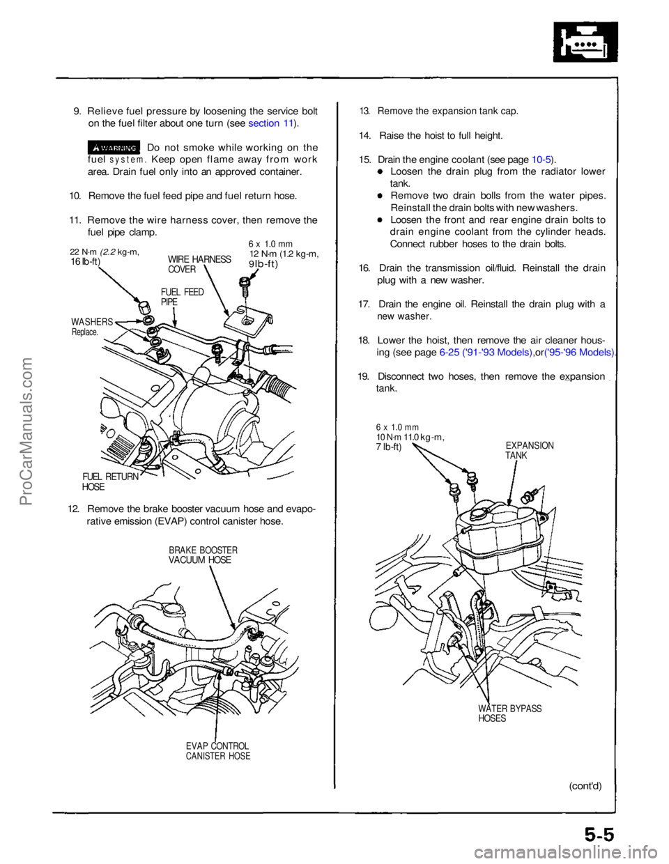
9. Relieve fuel pressure by loosening the service bolt
on the fuel filter about one turn (see section 11).
Do not smoke while working on the
fuel
system.
Keep open flame away from work
area. Drain fuel only into an approved container.
10. Remove the fuel feed pipe and fuel return hose.
11. Remove the wire harness cover, then remove the fuel pipe clamp.
22 N·m
(2.2 kg-m,
16 Ib-ft)
WIRE HARNESS
COVER
6 x 1.0 mm
12 N·m
(1.2 kg-m,
9 lb-ft)
FUEL FEED
PIPE
WASHERS
Replace.
FUEL RETURN
HOSE
12. Remove the brake booster vacuum hose and evapo- rative emission (EVAP) control canister hose.
BRAKE BOOSTER
VACUUM HOSE
EVAP CONTROL
CANISTER HOSE
13. Remove the expansion tank cap.
14. Raise the hoist to full height.
15. Drain the engine coolant (see page
10-5).
Loosen the drain plug from the radiator lower
tank. Remove two drain bolls from the water pipes.
Reinstall the drain bolts with new washers.
Loosen the front and rear engine drain bolts to
drain engine coolant from the cylinder heads.
Connect rubber hoses to the drain bolts.
16. Drain the transmission oil/fluid. Reinstall the drain plug with a new washer.
17. Drain the engine oil. Reinstall the drain plug with a
new washer.
18. Lower the hoist, then remove the air cleaner hous-
ing (see page 6-25 ('91-'93 Mode ls),or('95-'96 Models).
19. Disconnect two hoses, then remove the expansion
tank.
6 x 1.0 mm
10 N·m
11.0 kg-m,
7 lb-ft)
EXPANSION
TANK
WATER BYPASS
HOSES
(cont'd)ProCarManuals.com
Page 100 of 1640
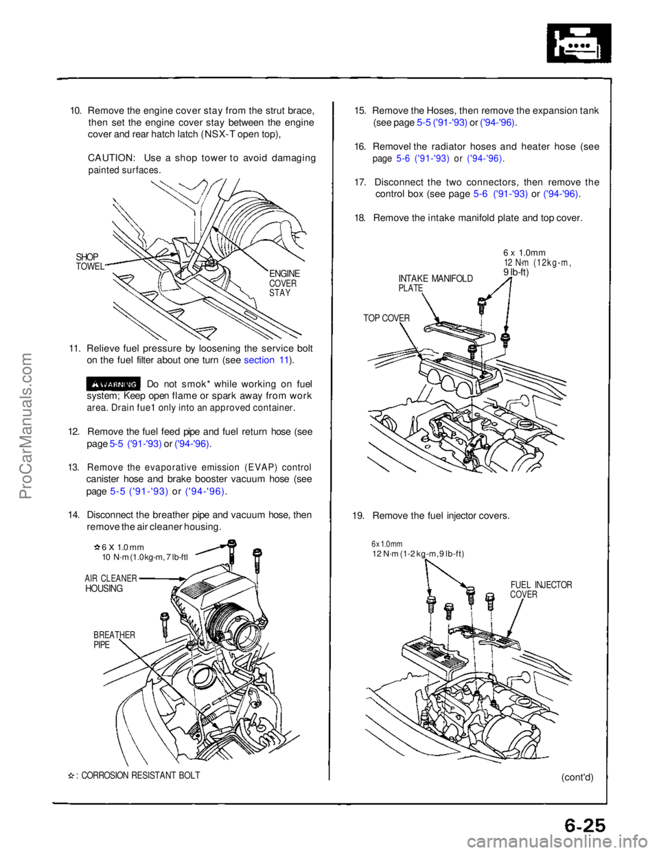
10. Remove the engine cover stay from the strut brace,
then set the engine cover stay between the engine
cover and rear hatch latch (NSX-T open top),
CAUTION: Use a shop tower to avoid damaging
painted surfaces.
SHOP
TOWEL
11. Relieve fuel pressure by loosening the service bolt on the fuel filter about one turn (see section 11).
Do not smok* while working on fuel
system; Keep open flame or spark away from work
area. Drain fue1 only into an approved container.
12. Remove the fuel feed pipe and fuel return hose (see page 5-5 ('91-'93) or ('94-'96).
13. Remove the evaporative emission (EVAP) control
canister hose and brake booster vacuum hose (see
page 5-5 ('91-'93) or ('94-'96).
14. Disconnect the breather pipe and vacuum hose, then remove the air cleaner housing.
6 x 1.0 mm
10 N·m (1.0 kg-m, 7 lb-ftl
AIR CLEANER
HOUSING
BREATHER
PIPE
: CORROSION RESISTANT BOLT
15. Remove the Hoses, then remove the expansion tank
(see page 5-5 ('91-'93) or ('94-'96).
16. Removel the radiator hoses and heater hose (see
page 5-6 ('91-'93) or ('94-'96).
17. Disconnect the two connectors, then remove the
control box (see page 5-6 ('91-'93) or ('94-'96).
18. Remove the intake manifold plate and top cover.
INTAKE MANIFOLD
PLATE
6 x
1.0mm
12 N·m (12kg-m,
9 lb-ft)
TOP COVER
19. Remove the fuel injector covers.
6 x 1.0 mm
12 N·m (1-2 kg-m, 9 lb-ft)
FUEL INJECTOR
COVER
(cont'd)
ENGINE
COVER
STAYProCarManuals.com
Page 251 of 1640
Fuel Suppl y Syste m
Fuel Pressur e
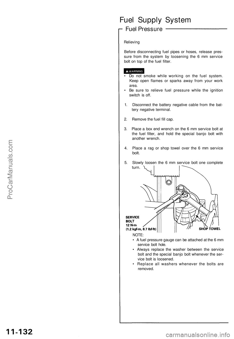
Relieving
Before disconnectin g fue l pipe s o r hoses , releas e pres -
sur e fro m th e syste m b y loosenin g th e 6 m m servic e
bol t o n to p o f th e fue l filter .
• D o no t smok e whil e workin g o n th e fue l system .
Kee p ope n flame s o r spark s awa y fro m you r wor k
area.
• B e sur e t o reliev e fue l pressur e whil e th e ignitio n
switc h i s off .
1 . Disconnec t th e batter y negativ e cabl e fro m th e bat -
ter y negativ e terminal .
2 . Remov e th e fue l fil l cap .
3 . Plac e a bo x en d wrenc h o n th e 6 m m servic e bol t a t
th e fue l filter , an d hol d th e specia l banj o bol t wit h
anothe r wrench .
4 . Plac e a ra g o r sho p towe l ove r th e 6 m m servic e
bolt.
5. Slowl y loose n th e 6 m m servic e bol t on e complet e
turn.
NOTE :
• A fue l pressur e gaug e ca n b e attache d a t th e 6 m m
servic e bol t hole .
• Alway s replac e th e washe r betwee n th e servic e
bol t an d th e specia l banj o bol t wheneve r th e ser -
vic e bol t i s loosened .
• Replac e al l washer s wheneve r th e bolt s ar e
removed .
ProCarManuals.com
Page 252 of 1640
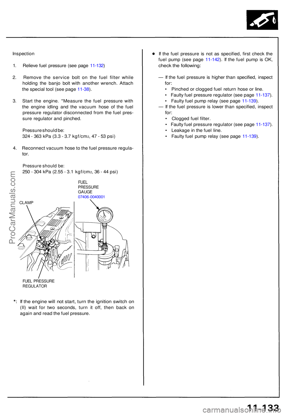
Inspection
1 . Reliev e fue l pressur e (se e pag e 11-132 )
2 . Remov e th e servic e bol t o n th e fue l filte r whil e
holdin g th e banj o bol t wit h anothe r wrench . Attac h
th e specia l too l (se e pag e 11-38 ).
3 . Star t th e engine . *Measur e th e fue l pressur e wit h
th e engin e idlin g an d th e vacuu m hos e o f th e fue l
pressur e regulato r disconnecte d fro m th e fue l pres -
sur e regulato r an d pinched .
Pressur e shoul d be :
32 4 - 36 3 kP a (3. 3 - 3. 7 kgf/cm
2, 4 7 - 5 3 psi )
4 . Reconnec t vacuu m hos e to th e fue l pressur e regula -
tor.
Pressur e shoul d be :
250 - 30 4 kP a (2.5 5 - 3. 1 kgf/cm2, 3 6 - 4 4 psi )
FUE LPRESSUR EGAUGE07406-004000 1
CLAMP
FUEL PRESSUR EREGULATO R
If th e engin e wil l no t start , tur n th e ignitio n switc h o n
(II ) wai t fo r tw o seconds , tur n i t off , the n bac k o n
agai n an d rea d th e fue l pressure . I
f th e fue l pressur e i s no t a s specified , firs t chec k th e
fue l pum p (se e pag e 11-142 ). I f th e fue l pum p i s OK ,
chec k th e following :
— If th e fue l pressur e is highe r tha n specified , inspec t
for:
• Pinche d o r clogge d fue l retur n hos e o r line .
• Fault y fue l pressur e regulato r (se e pag e 11-137 ).
• Fault y fue l pum p rela y (se e pag e 11-139 ).
— If th e fue l pressur e is lowe r tha n specified , inspec t
for:
• Clogge d fue l filter .
• Fault y fue l pressur e regulato r (se e pag e 11-137 ).
• Leakage in th e fue l line .
• Fault y fue l pum p rela y (se e pag e 11-139 ).
ProCarManuals.com
Page 258 of 1640
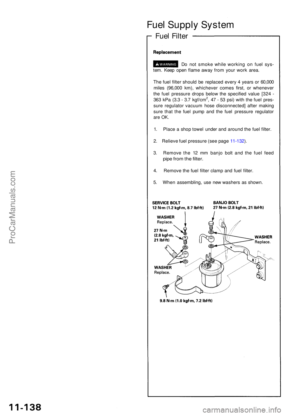
Fuel Suppl y Syste m
Fuel Filte r
Do no t smok e whil e workin g o n fue l sys -
tem . Kee p ope n flam e awa y fro m you r wor k area .
Th e fue l filte r shoul d b e replace d ever y 4 year s o r 60,00 0
mile s (96,00 0 km) , whicheve r come s first , o r wheneve r
th e fue l pressur e drop s belo w th e specifie d valu e [32 4 -
36 3 kP a (3. 3 - 3. 7 kgf/cm
2, 4 7 - 5 3 psi ) wit h th e fue l pres -
sur e regulato r vacuu m hos e disconnected ] afte r makin g
sur e tha t th e fue l pum p an d th e fue l pressur e regulato r
are OK .
1. Plac e a sho p towe l unde r an d aroun d th e fue l filter .
2 . Reliev e fue l pressur e (se e pag e 11-132 ).
3 . Remov e th e 1 2 m m banj o bol t an d th e fue l fee d
pipe fro m th e filter .
4. Remov e th e fue l filte r clam p an d fue l filter .
5 . Whe n assembling , us e ne w washer s a s shown .
ProCarManuals.com
Page 966 of 1640
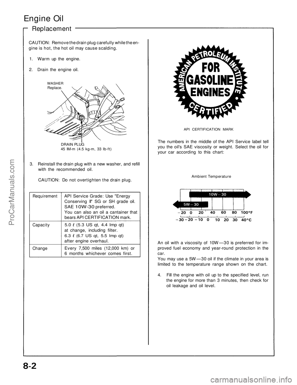
Engine Oil
Replacement
CAUTION: Remove the drain plug carefully while the en-
gine is hot, the hot oil may cause scalding.
1. Warm up the engine.
2. Drain the engine oil.
WASHER
Replace.
DRAIN PLUG
45 IM-m (4.5 kg-m, 33 Ib-ft)
3. Reinstall the drain plug with a new washer, and refill
with the recommended oil.
CAUTION: Do not overtighten the drain plug.
Requirement
API Service Grade: Use "Energy
Conserving II" SG or SH grade oil.
SAE
10W-30
preferred.
You can also an oil a cantainer that
bears API CERTIFICATION mark.
Capacity
5.0
(5.3
US qt, 4.4 Imp qt)
at change, including filter.
6.3
(6.7
US qt, 5.5 Imp qt)
after engine overhaul.
Change
Every 7,500 miles (12,000 km) or
6 months whichever comes first.
API CERTIFICATION MARK
The numbers in the middle of the API Service label tell
you the oil's SAE viscosity or weight. Select the oil for
your car according to this chart:
Ambient Temperature
An oil with a viscosity of 10W —30 is preferred for im-
proved fuel economy and year-round protection in the
car.
You may use a 5W —30 oil if the climate in your area is
limited to the temperature range shown on the chart.
4. Fill the engine with oil up to the specified level, run
the engine for more than 3 minutes, then check for
oil leakage and oil level.ProCarManuals.com
Page 988 of 1640
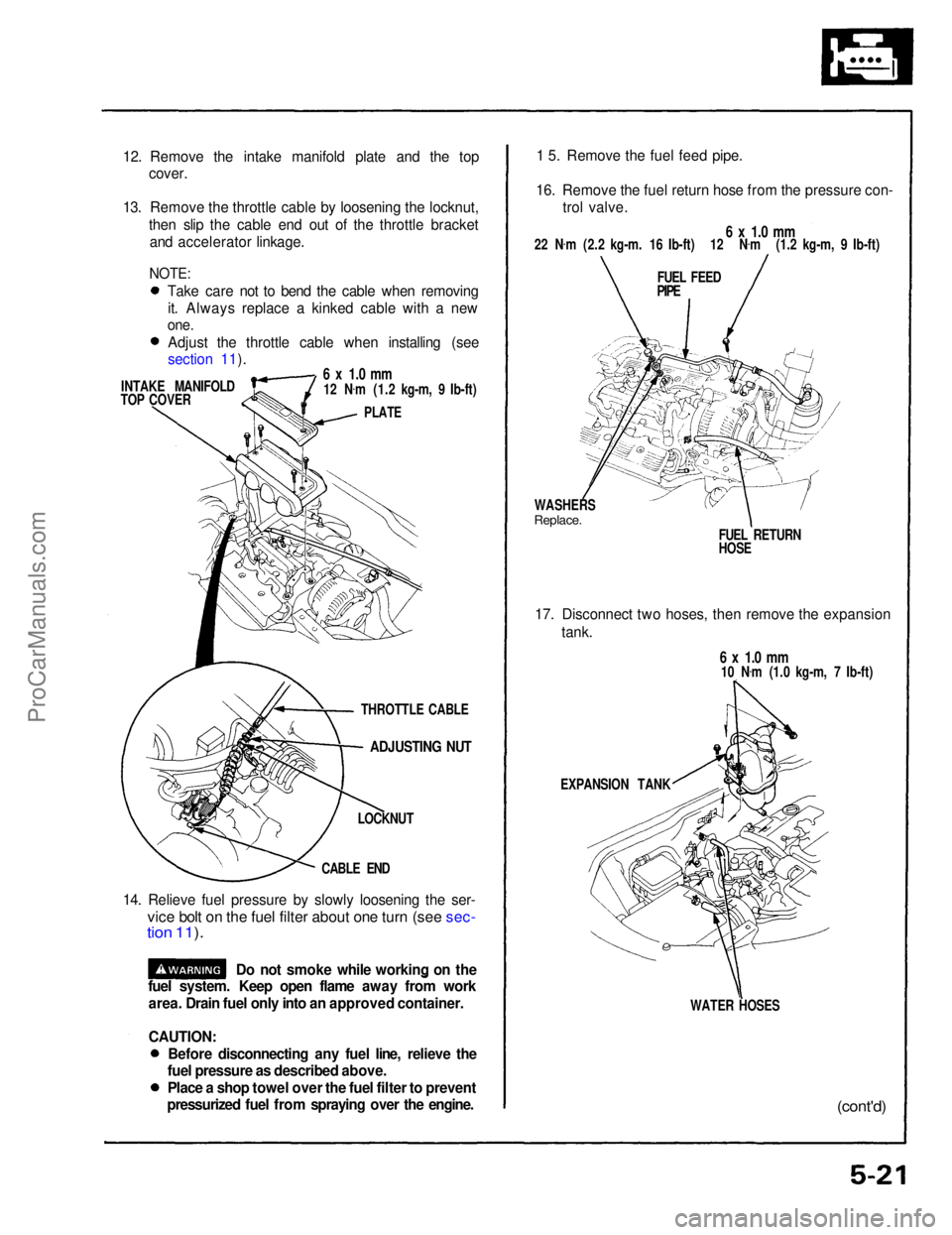
12. Remove the intake manifold plate and the top
cover.
13. Remove the throttle cable by loosening the locknut, then slip the cable end out of the throttle bracketand accelerator linkage.
INTAKE MANIFOLD
TOP COVER
6 x 1.0 mm
12 N .
m (1.2 kg-m, 9 Ib-ft)
PLATE
ADJUSTING NUT
LOCKNUT
CABLE END
14. Relieve fuel pressure by slowly loosening the ser-
vice bolt on the fuel filter about one turn (see sec-
tion 11 ).
1 5. Remove the fuel feed pipe.
16. Remove the fuel return hose from the pressure con- trol valve.
6 x 1.0 mm
22 N .
m (2.2 kg-m. 16 Ib-ft) 12 N .
m (1.2 kg-m, 9 Ib-ft)
FUEL FEED
PIPE
WASHERS
Replace.
FUEL RETURN
HOSE
17. Disconnect two hoses, then remove the expansion tank.
6 x 1.0 mm
10 N .
m (1.0 kg-m, 7 Ib-ft)
EXPANSION TANK
WATER HOSES
(cont'd)
Do not smoke while working on the
fuel system. Keep open flame away from work
area. Drain fuel only into an approved container.
CAUTION:
THROTTLE CABLE
NOTE:
Take care not to bend the cable when removingit. Always replace a kinked cable with a new
one.
Adjust the throttle cable when installing (see
section 11).
Before disconnecting any fuel line, relieve the
fuel pressure as described above.
Place a shop towel over the fuel filter to prevent
pressurized fuel from spraying over the engine.ProCarManuals.com
Page 1050 of 1640
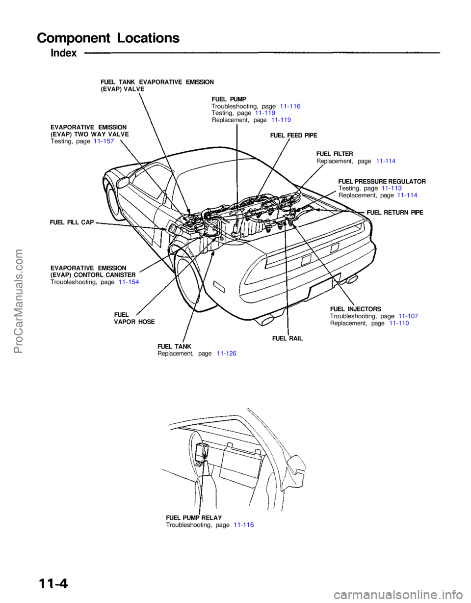
Component Locations
Index
FUEL TANK EVAPORATIVE EMISSION(EVAP) VALVE
EVAPORATIVE EMISSION (EVAP) TWO WAY VALVE
Testing, page 11-157
FUEL PUMP
Troubleshooting, page 11-116
Testing, page 11-119
Replacement, page 11-119
FUEL FEED PIPE
FUEL FILTERReplacement, page 11-114
FUEL PRESSURE REGULATOR
Testing, page 11-113
Replacement, page 11-114
FUEL RETURN PIPE
FUEL INJECTORS
Troubleshooting, page 11-107
Replacement, page 11-110
FUEL PUMP RELAY
Troubleshooting, page 11-116
FUEL RAIL
FUEL TANK
Replacement, page 11-126
FUEL
VAPOR HOSE
EVAPORATIVE EMISSION
(EVAP) CONTORL CANISTER
Troubleshooting, page 11-154
FUEL FILL CAPProCarManuals.com
Page 1054 of 1640
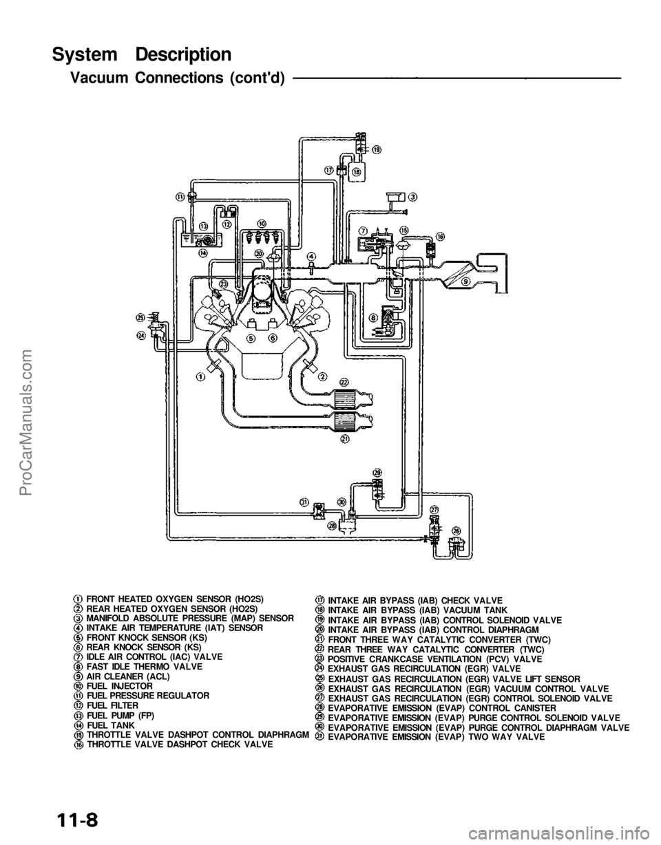
System Description
Vacuum Connections (cont'd)
FRONT HEATED OXYGEN SENSOR (HO2S)
REAR HEATED OXYGEN SENSOR (HO2S)
MANIFOLD ABSOLUTE PRESSURE (MAP) SENSORINTAKE AIR TEMPERATURE (IAT) SENSOR
FRONT KNOCK SENSOR (KS)
REAR KNOCK SENSOR (KS) IDLE AIR CONTROL (IAC) VALVE
FAST IDLE THERMO VALVE
AIR CLEANER (ACL) FUEL INJECTORFUEL PRESSURE REGULATOR
FUEL FILTER
FUEL PUMP (FP)
FUEL TANK
THROTTLE VALVE DASHPOT CONTROL DIAPHRAGM
THROTTLE VALVE DASHPOT CHECK VALVE INTAKE AIR BYPASS (IAB) CHECK VALVE
INTAKE AIR BYPASS (IAB) VACUUM TANK
INTAKE AIR BYPASS (IAB) CONTROL SOLENOID VALVE
INTAKE AIR BYPASS (IAB) CONTROL DIAPHRAGM
FRONT THREE WAY CATALYTIC CONVERTER (TWC)
REAR THREE WAY CATALYTIC CONVERTER (TWC)
POSITIVE CRANKCASE VENTILATION (PCV) VALVE
EXHAUST GAS RECIRCULATION (EGR) VALVE
EXHAUST GAS RECIRCULATION (EGR) VALVE LIFT SENSOR
EXHAUST GAS RECIRCULATION (EGR) VACUUM CONTROL VALVE
EXHAUST GAS RECIRCULATION (EGR) CONTROL SOLENOID VALVE
EVAPORATIVE EMISSION (EVAP) CONTROL CANISTER
EVAPORATIVE EMISSION (EVAP) PURGE CONTROL SOLENOID VALVE
EVAPORATIVE EMISSION (EVAP) PURGE CONTROL DIAPHRAGM VALVE
EVAPORATIVE EMISSION (EVAP) TWO WAY VALVEProCarManuals.com
Page 1108 of 1640
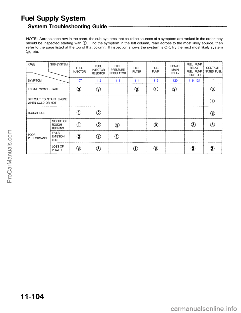
Fuel Supply System
System Troubleshooting Guide
NOTE: Across each row in the chart, the sub-systems that could be sources of a symptom are ranked in the order they should be inspected starting with . Find the symptom in the left column, read across to the most likely source, then
refer to the page listed at the top of that column. If inspection shows the system is OK, try the next most likely system
,
etc.
PAGE
SUB-SYSTEM
FUEL
INJECTOR FUEL
INJECTOR
RESISTOR
FUEL
PRESSURE
REGULATOR
FUEL
FILTER
FUEL
PUMP PGM-FI
MAIN
RELAY
FUEL PUMP
RELAY
FUEL PUMP
RESISTOR
CONTAMI-
NATED FUEL
SYMPTOM
ENGINE WON'T START
DIFFICULT TO START ENGINE
WHEN COLD OR HOT ROUGH IDLE
107
112
113
114
115
120
116,
124
POOR
PERFORMANCE
MISFIRE OR
ROUGH
RUNNING
FAILS
EMISSION
TEST
LOSS OF
POWERProCarManuals.com