radio ACURA NSX 1991 Service Repair Manual
[x] Cancel search | Manufacturer: ACURA, Model Year: 1991, Model line: NSX, Model: ACURA NSX 1991Pages: 1640, PDF Size: 60.48 MB
Page 610 of 1640
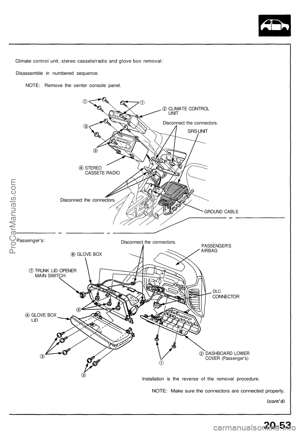
Climate control unit, stereo cassete/radio and glove box removal:
Disassemble in numbered sequence.
NOTE: Remove the center console panel.
CLIMATE CONTROL
UNIT
Disconnect the connectors.
SRS UNIT
Passenger's:
STEREO
CASSETE RADIO
Disconnect the connectors.
GROUND CABLE
GLOVE BOX
Disconnect the connectors.
TRUNK LID OPENER
MAIN SWITCH
PASSENGER'S
AIRBAG
DLC
CONNECTOR
GLOVE BOX
LID
DASHBOARD LOWER
COVER (Passenger's)
Installation is the reverse of the removal procedure.
NOTE: Make sure the connectors are connected properly.ProCarManuals.com
Page 879 of 1640
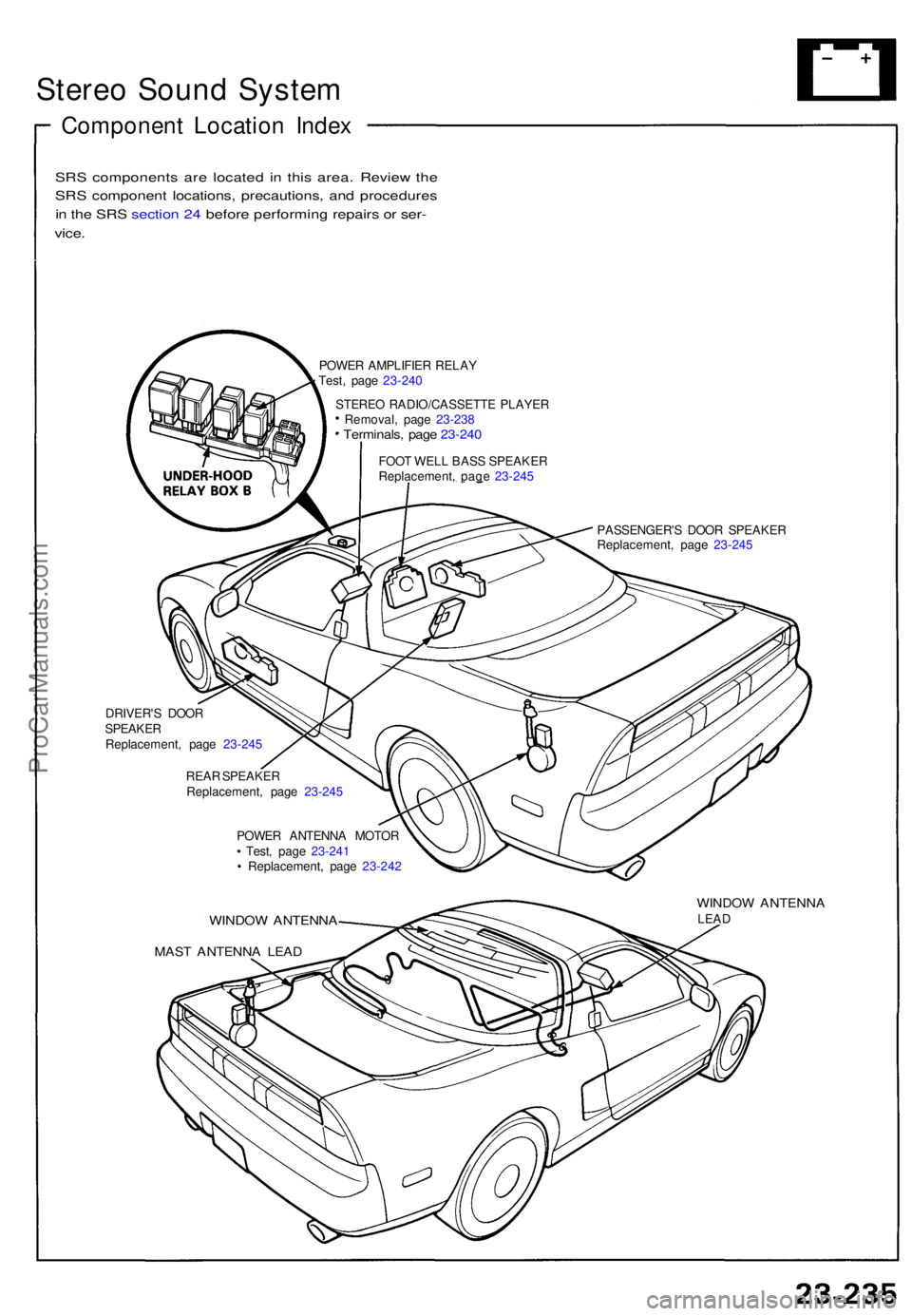
Stereo Soun d Syste m
Componen t Locatio n Inde x
SRS component s ar e locate d i n thi s area . Revie w th e
SR S componen t locations , precautions , an d procedure s
i n th e SR S sectio n 24 befor e performin g repair s o r ser -
vice .
POWE R AMPLIFIE R RELA Y
Test , pag e 23-24 0
STERE O RADIO/CASSETT E PLAYE R
Removal , pag e 23-23 8
Terminals , pag e 23-24 0
FOOT WEL L BAS S SPEAKE R
Replacement , pag e 23-24 5
PASSENGER' S DOO R SPEAKE R
Replacement , pag e 23-24 5
DRIVER' S DOO R
SPEAKE R
Replacement , pag e 23-24 5
REA R SPEAKE R
Replacement , pag e 23-24 5
POWE R ANTENN A MOTO R
• Test , pag e 23-24 1
• Replacement , pag e 23-24 2
WINDO W ANTENN A
MAST ANTENN A LEA D
WINDO W ANTENN ALEAD
ProCarManuals.com
Page 881 of 1640
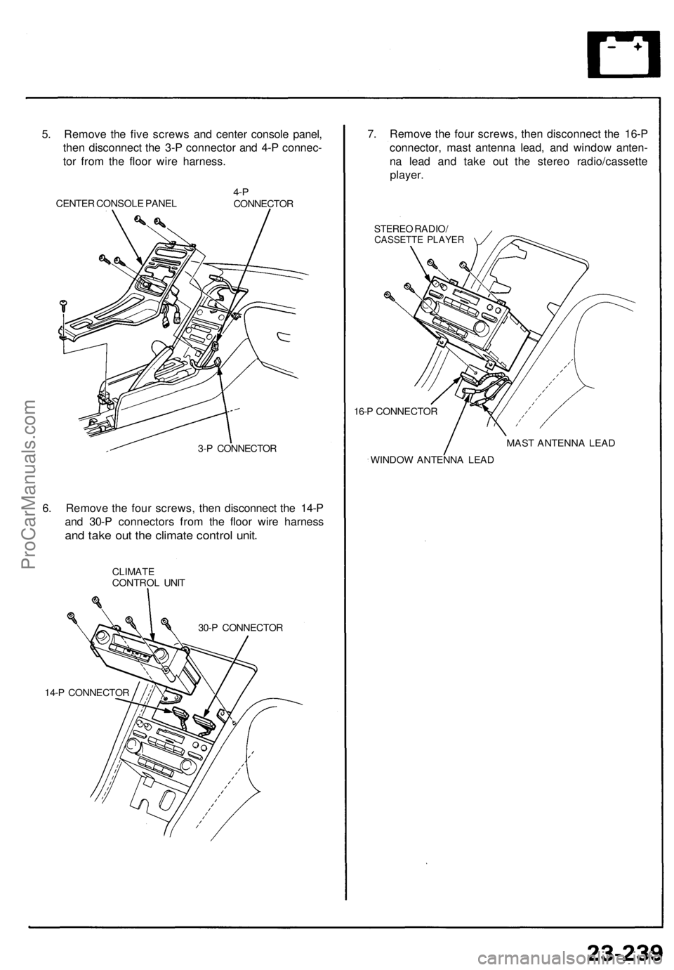
5. Remove the five screws and center console panel,
then disconnect the 3-P connector and 4-P connec-
tor from the floor wire harness.
CENTER CONSOLE PANEL
4-P
CONNECTOR
3-P CONNECTOR
6. Remove the four screws, then disconnect the 14-P
and 30-P connectors from the floor wire harness
and take out the climate control unit.
CLIMATE
CONTROL UNIT
30-P CONNECTOR
14-P CONNECTOR
7. Remove the four screws, then disconnect the 16-P
connector, mast antenna lead, and window anten-
na lead and take out the stereo radio/cassette
player.
STEREO RADIO/
CASSETTE PLAYER
16-P CONNECTOR
WINDOW ANTENNA LEAD
MAST ANTENNA LEADProCarManuals.com
Page 883 of 1640
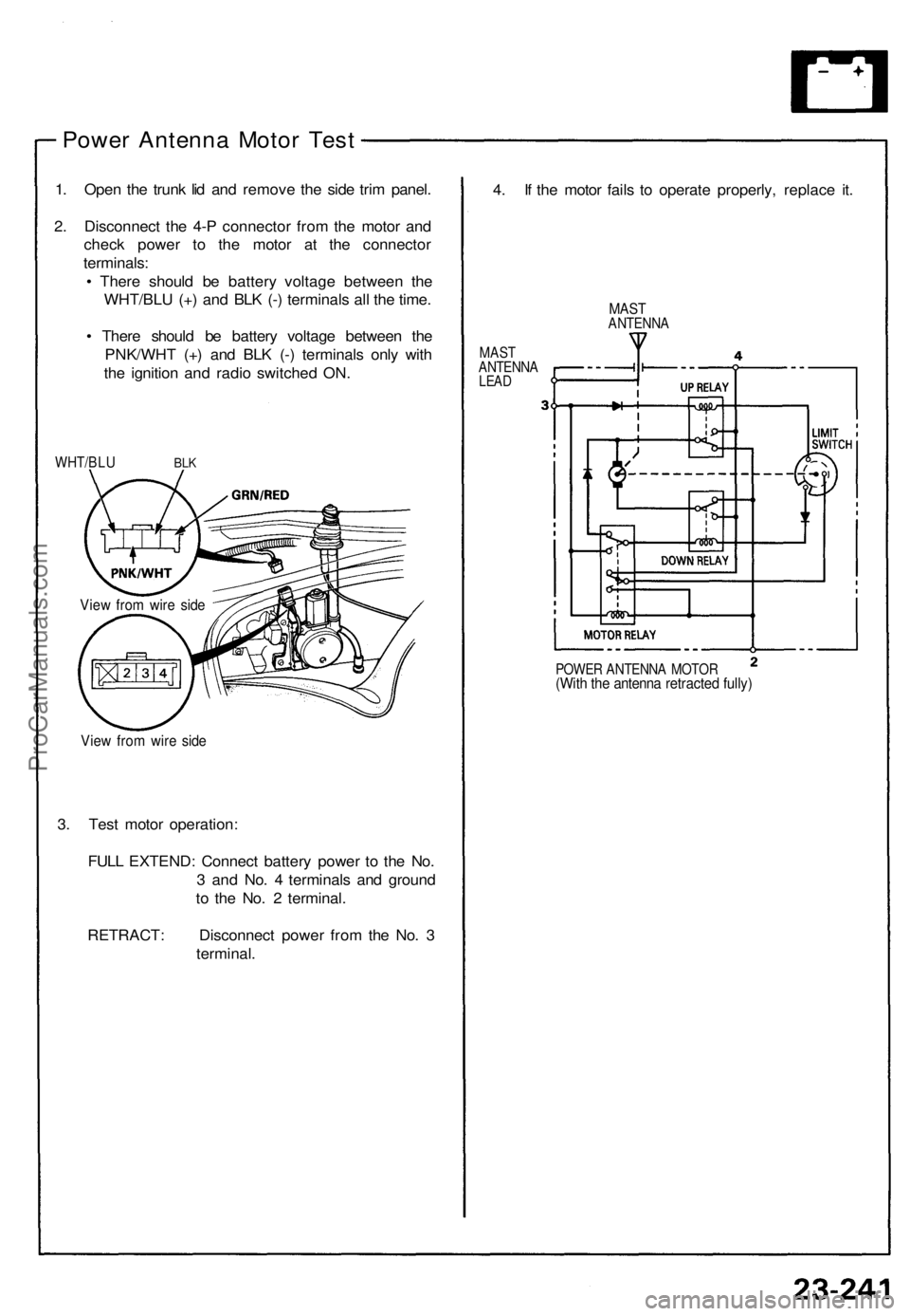
Power Antenna Motor Test
1. Open the trunk lid and remove the side trim panel.
2. Disconnect the 4-P connector from the motor and
check power to the motor at the connector
terminals:
• There should be battery voltage between the
WHT/BLU (+) and BLK (-) terminals all the time.
• There should be battery voltage between the
PNK/WHT (+) and BLK (-) terminals only with
the ignition and radio switched ON.
WHT/BLU
BLK
View from wire side
View from wire side
3. Test motor operation:
FULL EXTEND: Connect battery power to the No.
3 and No. 4 terminals and ground
to the No. 2 terminal.
RETRACT: Disconnect power from the No. 3
terminal.
4. If the motor fails to operate properly, replace it.
MAST
ANTENNA
MAST
ANTENNA
LEAD
POWER ANTENNA MOTOR
(With the antenna retracted fully)ProCarManuals.com
Page 885 of 1640
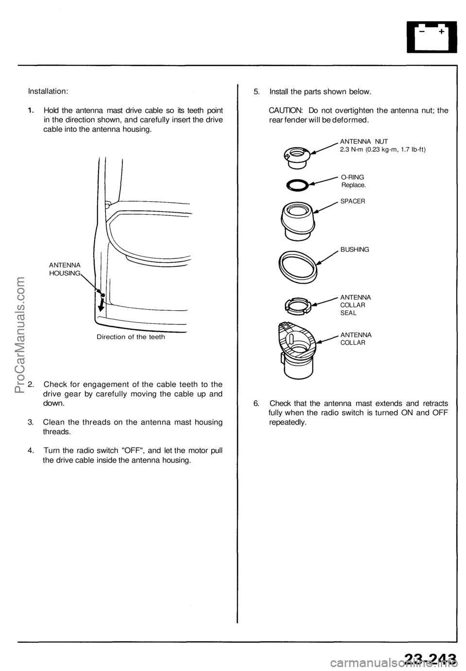
Installation:
Hold the antenna mast drive cable so its teeth point
in the direction shown, and carefully insert the drive
cable into the antenna housing.
ANTENNA
HOUSING
Direction of the teeth
2. Check for engagement of the cable teeth to the
drive gear by carefully moving the cable up and
down.
3. Clean the threads on the antenna mast housing
threads.
4. Turn the radio switch "OFF", and let the motor pull
the drive cable inside the antenna housing.
5. Install the parts shown below.
CAUTION: Do not overtighten the antenna nut; the
rear fender will be deformed.
ANTENNA NUT
2.3 N-m (0.23 kg-m, 1.7 Ib-ft)
O-RING
Replace.
SPACER
BUSHING
ANTENNA
COLLAR
SEAL
ANTENNA
COLLAR
6. Check that the antenna mast extends and retracts
fully when the radio switch is turned ON and OFF
repeatedly.ProCarManuals.com
Page 945 of 1640
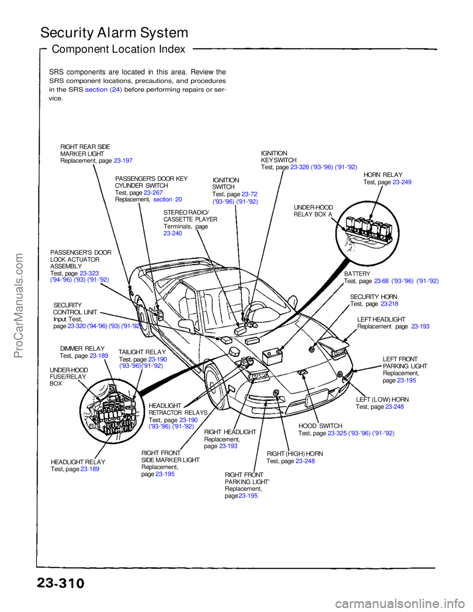
Security Alarm System
Component Location Index
SRS components are located in this area. Review the
SRS component locations, precautions, and procedures
i
n
the SRS section (24) before performing repairs or ser-
vice.
RIGHT REAR SIDE
MARKER LIGHT
Replacement, page 23-197 PASSENGER'S DOOR KEY
CYLINDER SWITCH
Test, page 23-267
Replacement, section 20
STEREO RADIO/
CASSETTE PLAYER
Terminals, page
23-240
IGNITION
SWITCH
Test, page 23-72
('93-'96) ('91-'92)
IGNITION
KEY SWITCH
Test, page 23-326 ('93-'96) ('91-'92)
UNDER-HOOD
RELAY BOX A
HORN RELAY
Test, page 23-249
BATTERY
Teat, page 23-68 ('93-'96) ('91-'92)
SECURITY HORN
Test, page 23-218 LEFT HEADLIGHT
Replacement page 23-193
LEFT FRONT
PARKING LIGHT
Replacement,
page 23-195
LEFT (LOW) HORN
Test, page 23-248
HOOD SWITCH
Test, page 23-325 ('93-'96) ('91-'92)
RIGHT (HIGH) HORN
Test, page 23-248
RIGHT FRONT
PARKING LIGHT
Replacement,
page 23-195
RIGHT HEADLIGHT
Replacement,
page 23-193
RIGHT FRONT
SIDE MARKER LIGHT
Replacement,
page 23-195 HEADLIGHT
RETRACTOR RELAYS
Test, page 23-190
('93-'96) ('91-'92)
HEADLIGHT RELAY
Test, page 23-189 TAILIGHT RELAY
Test, page 23-190
('93-'96)('91-'92)
UNDER-HOOD
FUSE/RELAY
BOX
DIMMER RELAY
Test, page 23-189
SECURITY
CONTROL UNIT
Input Test,
page 23-320 ('94-'96) ('93) ('91-'92)
PASSENGER'S DOOR
LOCK ACTUATOR
ASSEMBLY
Test, page 23-323
('94-'96) ('93) ('91-'92)ProCarManuals.com
Page 948 of 1640
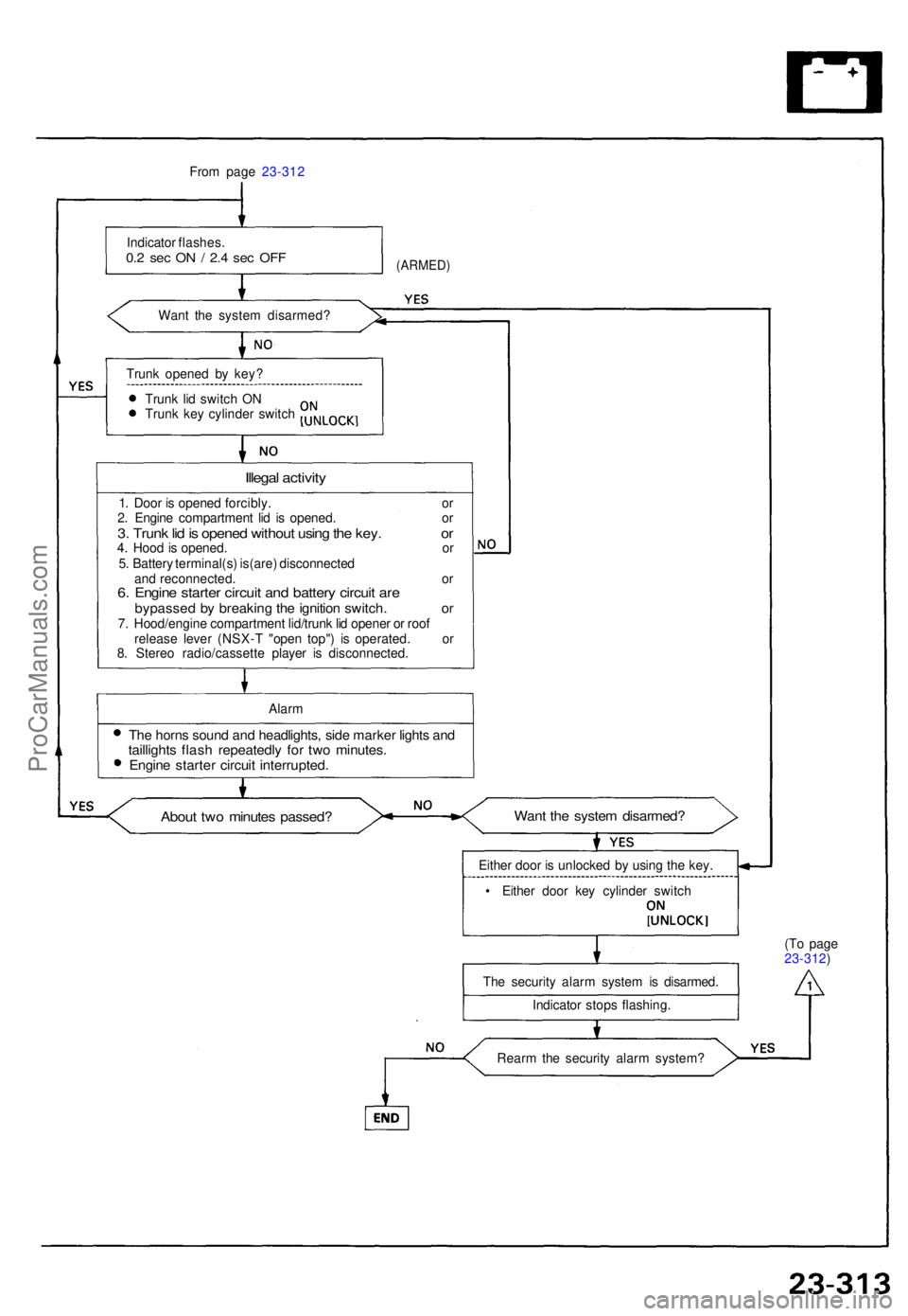
From pag e 23-31 2
Indicato r flashes .
0.2 se c O N / 2. 4 se c OF F
Wan t th e syste m disarmed ?
(ARMED)
Trunk opene d b y key ?
Trun k li d switc h O N
Trun k ke y cylinde r switc h
Illegal activit y
1. Doo r i s opene d forcibly . o r
2 . Engin e compartmen t li d i s opened . o r
3. Trun k li d is opene d withou t usin g th e key . o r4. Hoo d is opened . o r
5 . Batter y terminal(s ) is(are ) disconnecte d
an d reconnected . o r
6. Engin e starte r circui t an d batter y circui t ar ebypasse d b y breakin g th e ignitio n switch . o r7. Hood/engin e compartmen t lid/trun k li d opene r o r roo f
releas e leve r (NSX- T "ope n top" ) i s operated . o r
8 . Stere o radio/cassett e playe r i s disconnected .
Alar m
The horn s soun d an d headlights , sid e marke r light s an dtaillight s flas h repeatedl y fo r tw o minutes .Engine starte r circui t interrupted .
About tw o minute s passed ?Want th e syste m disarmed ?
Either doo r i s unlocke d b y usin g th e key .
• Eithe r doo r ke y cylinde r switc h
Th e securit y alar m syste m is disarmed .
Indicato r stop s flashing . (T
o pag e
23-312 )
Rear m th e securit y alar m system ?
ProCarManuals.com
Page 1079 of 1640

II. ENGINE CONTROL MODULE (ECM) Reset Procedure
1. Turn the ignition switch off.
2. Remove the CLOCK (7.5 A) fuse from the under-hood fuse/relay box for 10 seconds to reset ECM.
NOTE: Disconnecting the CLOCK fuse also cancels the radio preset stations and the clock setting. Make note of
the radio presets before removing the fuse so you can reset them.
III. Final Procedure (this procedure must be done after any troubleshooting)
1. Remove the Jumper Wire.
NOTE: If the Service Check Connector is jumped, the MIL will stay on.
2. Do the ECM Reset Procedure.
3. Set the radio preset stations and the clock setting.
(cont'd)
CLOCK
(7.5 A) FUSE
UNDER-HOOD
FUSE/RELAY BOXProCarManuals.com
Page 1208 of 1640
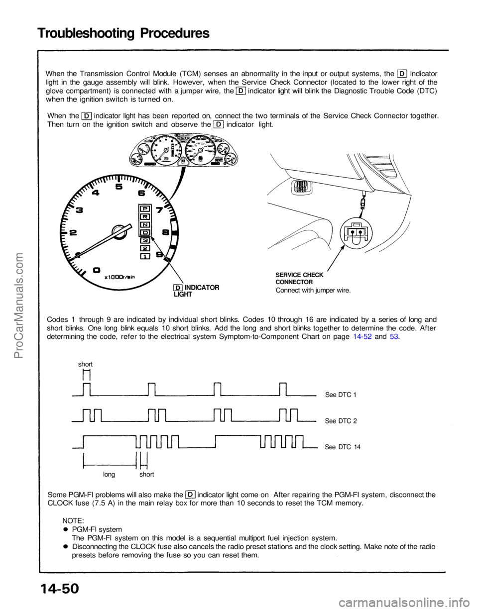
Troubleshooting Procedures
When the Transmission Control Module (TCM) senses an abnormality in the input or output systems, the indicator
light in the gauge assembly will blink. However, when the Service Check Connector (located to the lower right of the glove compartment) is connected with a jumper wire, the indicator light will blink the Diagnostic Trouble Code (DTC)
when the ignition switch is turned on.
When the indicator light has been reported on, connect the two terminals of the Service Check Connector together.
Then turn on the ignition switch and observe the indicator light.
Codes 1 through 9 are indicated by individual short blinks. Codes 10 through 16 are indicated by a series of long and
short blinks. One long blink equals 10 short blinks. Add the long and short blinks together to determine the code. After
determining the code, refer to the electrical system Symptom-to-Component Chart on page 14-52 and 53. SERVICE CHECK
CONNECTOR
Connect with jumper wire.
INDICATOR
Some PGM-FI problems will also make the indicator light come on After repairing the PGM-FI system, disconnect the
CLOCK fuse (7.5 A) in the main relay box for more than 10 seconds to reset the TCM memory.
long short
See DTC 1
See DTC 2
See DTC 14
LIGHT
short
PGM-FI system
The PGM-FI system on this model is a sequential multiport fuel injection system. Disconnecting the CLOCK fuse also cancels the radio preset stations and the clock setting. Make note of the radio
presets before removing the fuse so you can reset them.
NOTE:ProCarManuals.com
Page 1209 of 1640
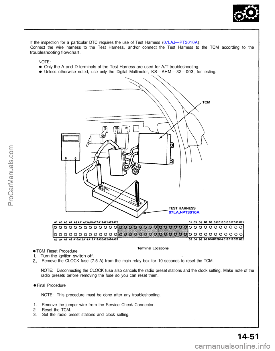
If the inspection for a particular DTC requires the use of Test Harness (07LAJ—PT3010A):
Connect the wire harness to the Test Harness, and/or connect the Test Harness to the TCM according to the
troubleshooting flowchart.
TCM
TEST HARNESS
Terminal Locations
TCM Reset Procedure
Turn the ignition switch off. -
, Remove the CLOCK fuse (7.5 A) from the main relay box for 10 seconds to reset the TCM.
1
2
NOTE: Disconnecting the CLOCK fuse also cancels the radio preset stations and the clock setting. Make note of the
radio presets before removing the fuse so you can reset them.
Final Procedure NOTE: This procedure must be done after any troubleshooting.
1. Remove the jumper wire from the Service Check Connector.
2. Reset the TCM. 3. Set the radio preset stations and clock setting.
Only the A and D terminals of the Test Harness are used for A/T troubleshooting.
Unless otherwise noted, use only the Digital Multimeter, KS—AHM —32—003, for testing.
07LAJ-PT3010A
NOTE:ProCarManuals.com