battery replacement ACURA NSX 1997 Service Repair Manual
[x] Cancel search | Manufacturer: ACURA, Model Year: 1997, Model line: NSX, Model: ACURA NSX 1997Pages: 1503, PDF Size: 57.08 MB
Page 358 of 1503
Power Door Locks
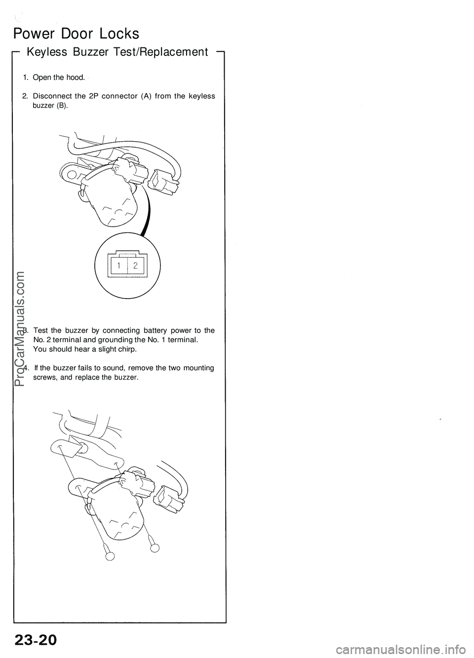
Keyless Buzzer Test/Replacement
1. Open the hood.
2. Disconnect the 2P connector (A) from the keyless
buzzer (B).
3. Test the buzzer by connecting battery power to the
No. 2 terminal and grounding the No. 1 terminal.
You should hear a slight chirp.
4. If the buzzer fails to sound, remove the two mounting
screws, and replace the buzzer.ProCarManuals.com
Page 659 of 1503
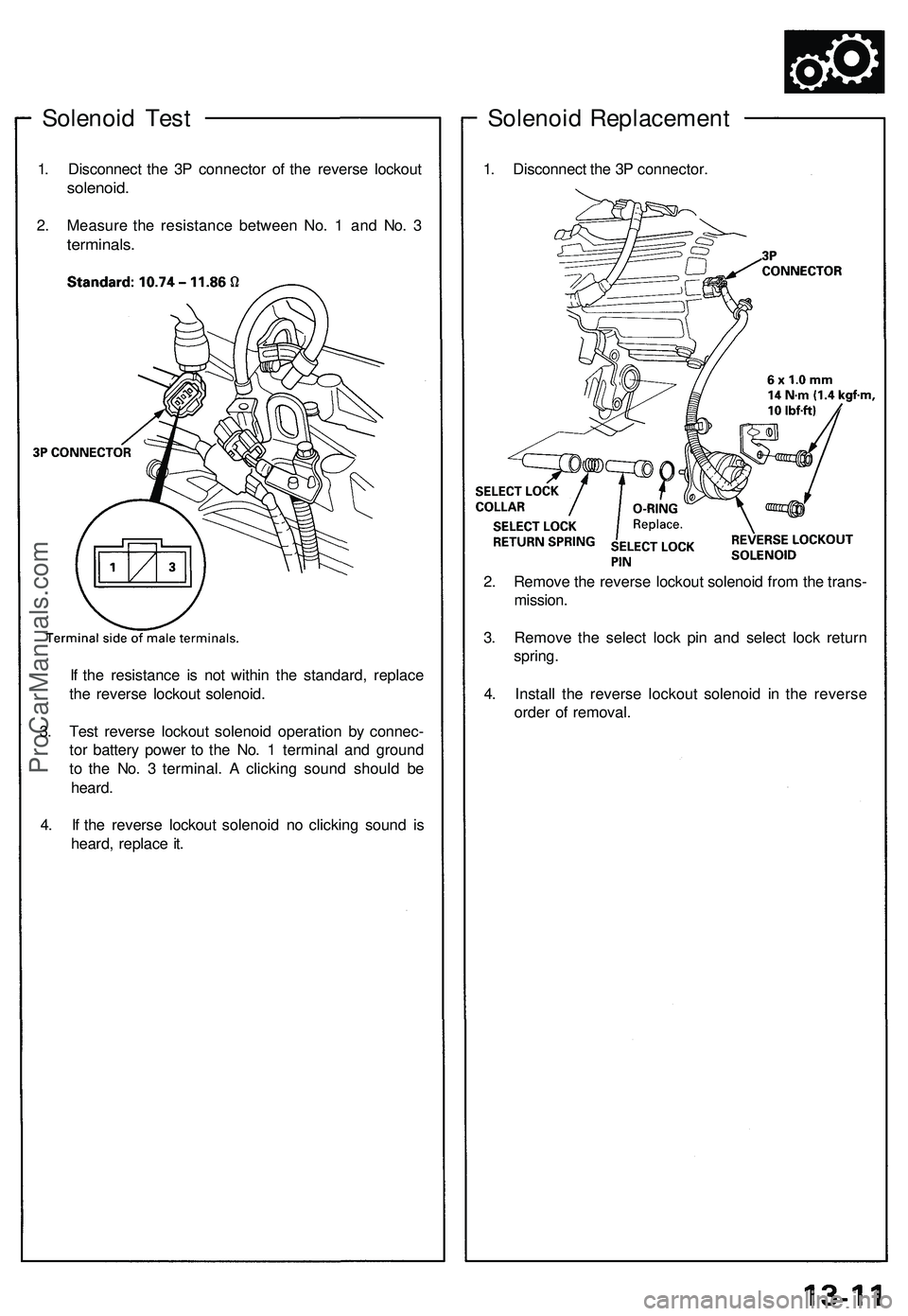
Solenoid Test
1. Disconnect the 3P connector of the reverse lockout
solenoid.
2. Measure the resistance between No. 1 and No. 3
terminals.
If the resistance is not within the standard, replace
the reverse lockout solenoid.
3. Test reverse lockout solenoid operation by connec-
tor battery power to the No. 1 terminal and ground
to the No. 3 terminal. A clicking sound should be
heard.
4. If the reverse lockout solenoid no clicking sound is
heard, replace it.
Solenoid Replacement
1. Disconnect the 3P connector.
2. Remove the reverse lockout solenoid from the trans-
mission.
3. Remove the select lock pin and select lock return
spring.
4. Install the reverse lockout solenoid in the reverse
order of removal.ProCarManuals.com
Page 1197 of 1503
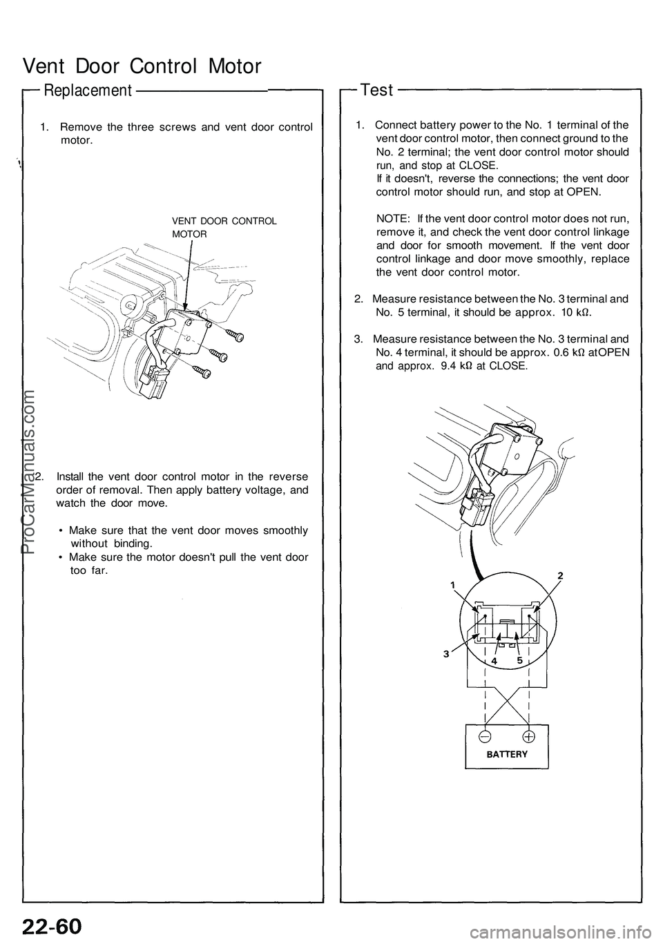
Vent Door Control Motor
Replacement —————————
1. Remove the three screws and vent door control
motor.
VENT DOOR CONTROL
MOTOR
2. Install the vent door control motor in the reverse
order of removal. Then apply battery voltage, and
watch the door move.
• Make sure that the vent door moves smoothly
without binding.
• Make sure the motor doesn't pull the vent door
too
far.
Test
1. Connect battery power to the No. 1 terminal of the
vent door control motor, then connect ground to the
No. 2 terminal; the vent door control motor should
run, and stop at CLOSE.
If it doesn't, reverse the connections; the vent door
control motor should run, and stop at OPEN.
NOTE: If the vent door control motor does not run,
remove it, and check the vent door control linkage
and door for smooth movement. If the vent door
control linkage and door move smoothly, replace
the vent door control motor.
2. Measure resistance between the No. 3 terminal and
No. 5 terminal, it should be approx. 10
3. Measure resistance between the No. 3 terminal and
No. 4 terminal, it should be approx. 0.6 at OPEN
and approx. 9.4 at CLOSE.ProCarManuals.com
Page 1216 of 1503

Replacement
1. Disconnec t th e negativ e cabl e fro m th e battery .
2 . Remov e th e fron t bumpe r (se e sectio n 20 ).
3 . Recove r th e refrigeran t usin g a R-134 a refrigeran t
Recover/Recycling/Chargin g Syste m (se e pag e
22-73 ).
4 . Disconnec t th e discharg e lin e C an d th e condense r
line s fro m th e condenser . Ca p th e ope n fitting s
immediatel y t o kee p moistur e an d dir t ou t o f th e
system .
(Right Condenser )
(Left Condenser )
CONDENSER
LIN E C
CONDENSE R
LIN E A
CONDENSE RLINE A
DISCHARG ELINEC
5. Disconnec t th e connecto r fro m th e condense r fan ,
remov e th e tw o mountin g bolt s an d nut , the n
remov e th e condenser .
CORROSIO N RESISTAN T BOL T
(Righ t Condenser )
RIGHT CONDENSE R
MOUNTING BOLT S6 x 1. 0 m m9.8 N- m (1. 0 kgf-m , 7. 2 Ibf-ft )
(Left Condenser )CONNECTORNUT
LEF T CONDENSE R
MOUNTING BOLT S6 x 1. 0 m m9.8 N- m (1. 0 kgf-m , 7. 2 Ibf-ft )
6. Instal l th e condense r i n th e revers e orde r o f
removal ; and :
• I f you'r e installin g a ne w condenser , ad d
refrigeran t oi l (ND-OI L 8 ) (se e pag e 22-69 ).
• Replac e O-ring s wit h ne w one s a t eac h fitting ,
an d appl y refrigeran t oi l t o them .
NOTE : B e sur e t o us e th e righ t O-ring s fo r
R-134 a t o avoi d leakage .
• Charg e th e syste m (se e pag e 22-91 ), an d tes t it s
performanc e (se e pag e 22-70 ).
NU TCONNECTO R
ProCarManuals.com
Page 1220 of 1503
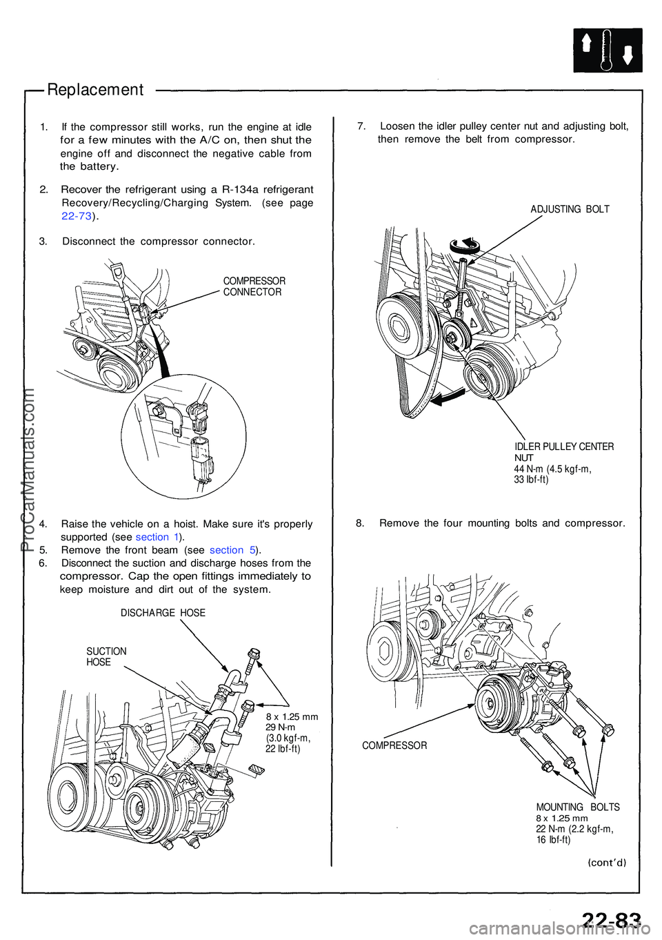
Replacement
1. I f th e compresso r stil l works , ru n th e engin e a t idl e
for a fe w minute s wit h th e A/ C on , the n shu t th e
engin e of f an d disconnec t th e negativ e cabl e fro m
the battery .
2. Recove r th e refrigeran t usin g a R-134 a refrigeran t
Recovery/Recycling/Chargin g System . (se e pag e
22-73 ).
3 . Disconnec t th e compresso r connector .
COMPRESSO R
CONNECTO R
4. Rais e th e vehicl e o n a hoist . Mak e sur e it' s properl y
supporte d (se e sectio n 1 ).
5 . Remov e th e fron t bea m (se e sectio n 5 ).
6 . Disconnec t th e suctio n an d discharg e hose s fro m th e
compressor . Ca p th e ope n fitting s immediatel y t o
kee p moistur e an d dir t ou t o f th e system .
DISCHARG E HOS E
SUCTIO N
HOS E
8 x 1.2 5 mm29 N- m(3.0 kgf-m ,
2 2 Ibf-ft )
7. Loose n th e idle r pulle y cente r nu t an d adjustin g bolt ,
the n remov e th e bel t fro m compressor .
ADJUSTING BOL T
IDLE R PULLE Y CENTE R
NUT44 N- m (4. 5 kgf-m ,
3 3 Ibf-ft )
8. Remov e th e fou r mountin g bolt s an d compressor .
COMPRESSO R
MOUNTING BOLT S8 x 1.2 5 mm22 N- m (2. 2 kgf-m ,
1 6 Ibf-ft )
ProCarManuals.com
Page 1240 of 1503
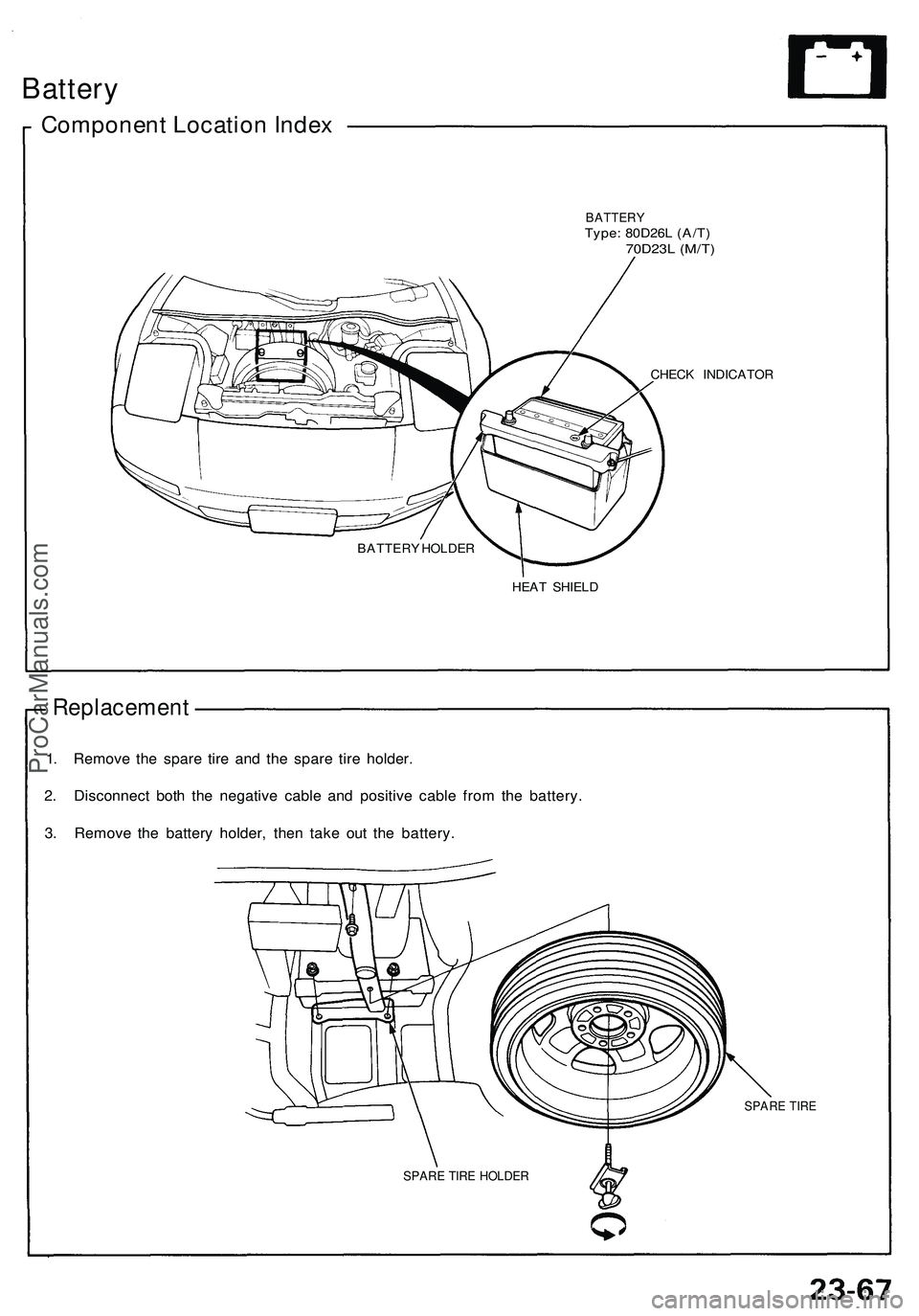
Battery
Component Location Index
BATTERY
Type: 80D26L (A/T)
70D23L (M/T)
CHECK INDICATOR
HEAT SHIELD
Replacement
1. Remove the spare tire and the spare tire holder.
2. Disconnect both the negative cable and positive cable from the battery.
3. Remove the battery holder, then take out the battery.
SPARE TIRE
BATTERY HOLDER
SPARE TIRE HOLDERProCarManuals.com
Page 1253 of 1503
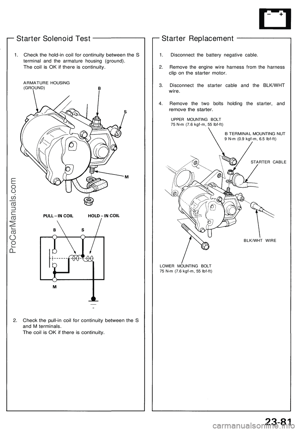
Starter Solenoid Test
1. Check the hold-in coil for continuity between the S
terminal and the armature housing (ground).
The coil is OK if there is continuity.
ARMATURE HOUSING
(GROUND)
2. Check the pull-in coil for continuity between the S
and M terminals.
The coil is OK if there is continuity.
Starter Replacement
1. Disconnect the battery negative cable.
2. Remove the engine wire harness from the harness
clip on the starter motor.
3. Disconnect the starter cable and the BLK/WHT
wire.
4. Remove the two bolts holding the starter, and
remove the starter.
UPPER MOUNTING BOLT
75 N-m (7.6 kgf-m, 55 Ibf-ft)
B TERMINAL MOUNTING NUT
9 N-m (0.9 kgf-m, 6.5 Ibf-ft)
STARTER CABLE
LOWER MOUNTING BOLT
75 N-m (7.6 kgf-m, 55 Ibf-ft)
BLK/WHT WIREProCarManuals.com
Page 1400 of 1503
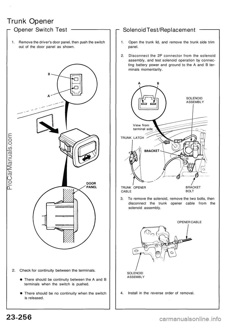
Trunk Opener
Opener Switch Test
1. Remove the driver's door panel, then push the switch
out of the door panel as shown.
2. Check for continuity between the terminals.
There should be continuity between the A and B
terminals when the switch is pushed.
There should be no continuity when the switch
is released.
Solenoid Test/Replacement
1. Open the trunk lid, and remove the trunk side trim
panel.
2. Disconnect the 2P connector from the solenoid
assembly, and test solenoid operation by connec-
ting battery power and ground to the A and B ter-
minals momentarily.
SOLENOID
ASSEMBLY
TRUNK LATCH
TRUNK OPENER
CABLE
BRACKET
BOLT
3. To remove the solenoid, remove the two bolts, then
disconnect the trunk opener cable from the
solenoid assembly.
OPENER CABLE
SOLENOID
ASSEMBLY
4. Install in the reverse order of removal.ProCarManuals.com
Page 1492 of 1503
Damaged Airbag or Tensioner Special Proce-
dure.
If an airbag or tensioner cannot be
deployed or triggered, it should not be treated as
normal scrap; it should still be considered a poten-
tially explosive device that can cause serious
injury.
1. If installed in a vehicle, follow the removal proce-
dures in this section.
2. Intertwine the stripped ends of the two airbag or ten-
sioner wires to make a short circuit.
3. Package the airbag or tensioner in exactly the same
packaging that the new replacement part came in.
4. Mark the outside of the box "DAMAGED AIRBAG
(or TENSIONER) NOT DEPLOYED" so it does not
get confused with your parts stock. If applicable,
also note on the box the VIN of the vehicle from
which it was removed.
5. Contact your Acura District Technical Manager for
how and where to return it for disposal.
Deployment Tool: Check Procedure.
1. Connect the yellow clips to both switch protector
handles on the tool; connect the tool to a battery.
2. Push the operation switch: green means the tool is
OK; red means the tool is faulty.
3. Disconnect the battery and the yellow clips.ProCarManuals.com