key ACURA NSX 1997 Service Repair Manual
[x] Cancel search | Manufacturer: ACURA, Model Year: 1997, Model line: NSX, Model: ACURA NSX 1997Pages: 1503, PDF Size: 57.08 MB
Page 144 of 1503
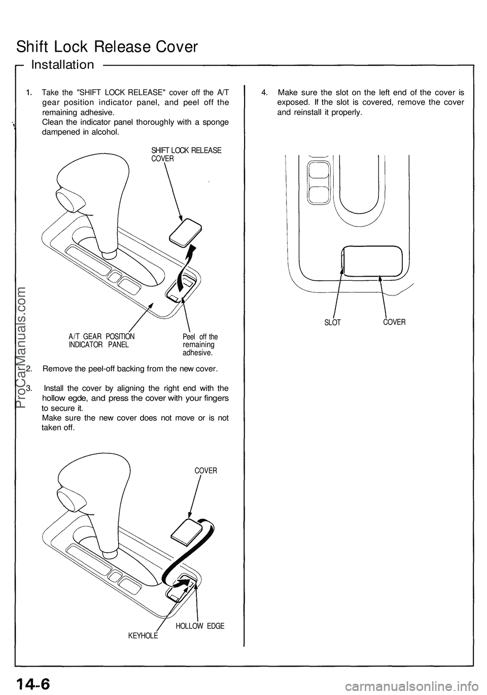
Shift Loc k Releas e Cove r
Installatio n ——————————
Take th e "SHIF T LOC K RELEASE " cove r of f th e A/ T
gea r positio n indicato r panel , an d pee l of f th e
remainin g adhesive .
Clea n th e indicato r pane l thoroughl y wit h a spong e
dampene d in alcohol .
SHIFT LOC K RELEAS ECOVER
A/ T GEA R POSITIO N
INDICATO R PANE L Pee
l of f th e
remainin gadhesive .
2. Remov e th e peel-of f backin g fro m th e ne w cover .
3 . Instal l th e cove r b y alignin g th e righ t en d wit h th e
hollo w egde , an d pres s th e cove r wit h you r finger s
to secur e it .
Mak e sur e th e ne w cove r doe s no t mov e o r i s no t
take n off .
COVE R
HOLLO W EDG E
KEYHOL E
4. Mak e sur e th e slo t o n th e lef t en d o f th e cove r i s
exposed . I f th e slo t i s covered , remov e th e cove r
an d reinstal l i t properly .
SLOT COVE
R
ProCarManuals.com
Page 277 of 1503
Description
Security Alar m System :
Th e securit y alar m syste m is a n anti-thef t alar m system . I f someon e trie s t o ope n th e trunk , hoo d o r eithe r doo r withou t
th e ignitio n key , o r i f th e roo f i s no t full y latched , th e securit y contro l uni t sense s a signa l fro m th e sensor s an d activate s
relay s t o flas h th e headlight s an d soun d th e hor n fo r abou t tw o minutes .
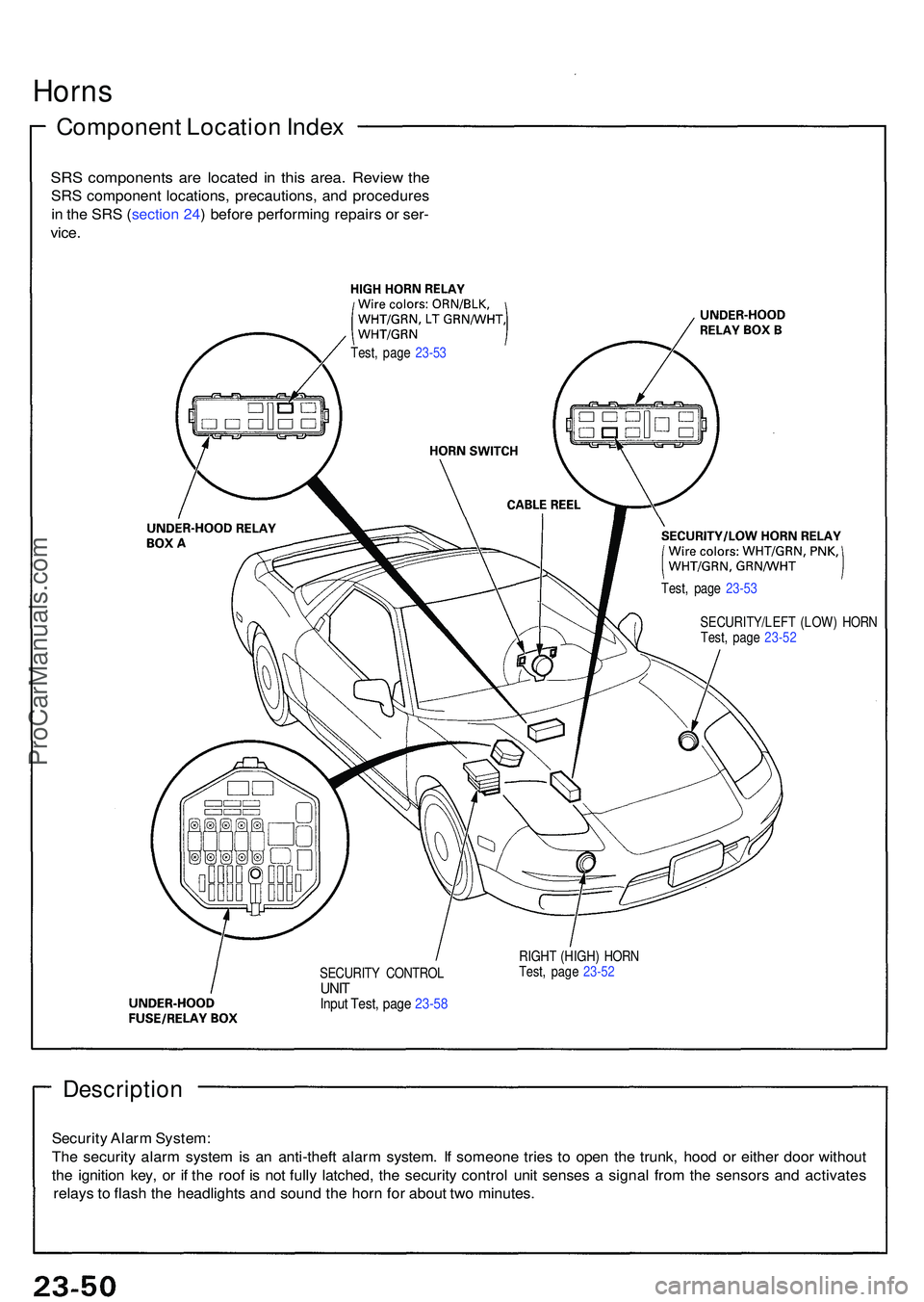
SECURIT Y CONTRO LUNITInpu t Test , pag e 23-5 8
RIGH T (HIGH ) HOR N
Test , pag e 23-5 2
Horn s
Componen t Locatio n Inde x
SRS component s ar e locate d i n thi s area . Revie w th e
SR S componen t locations , precautions , an d procedure s
i n th e SR S (sectio n 24 ) befor e performin g repair s o r ser -
vice .
Test , pag e 23-5 3
Test, pag e 23-5 3
SECURITY/LEF T (LOW ) HOR N
Test , pag e 23-5 2
ProCarManuals.com
Page 353 of 1503
+
Power Doo r Lock s
Componen t Locatio n Inde x
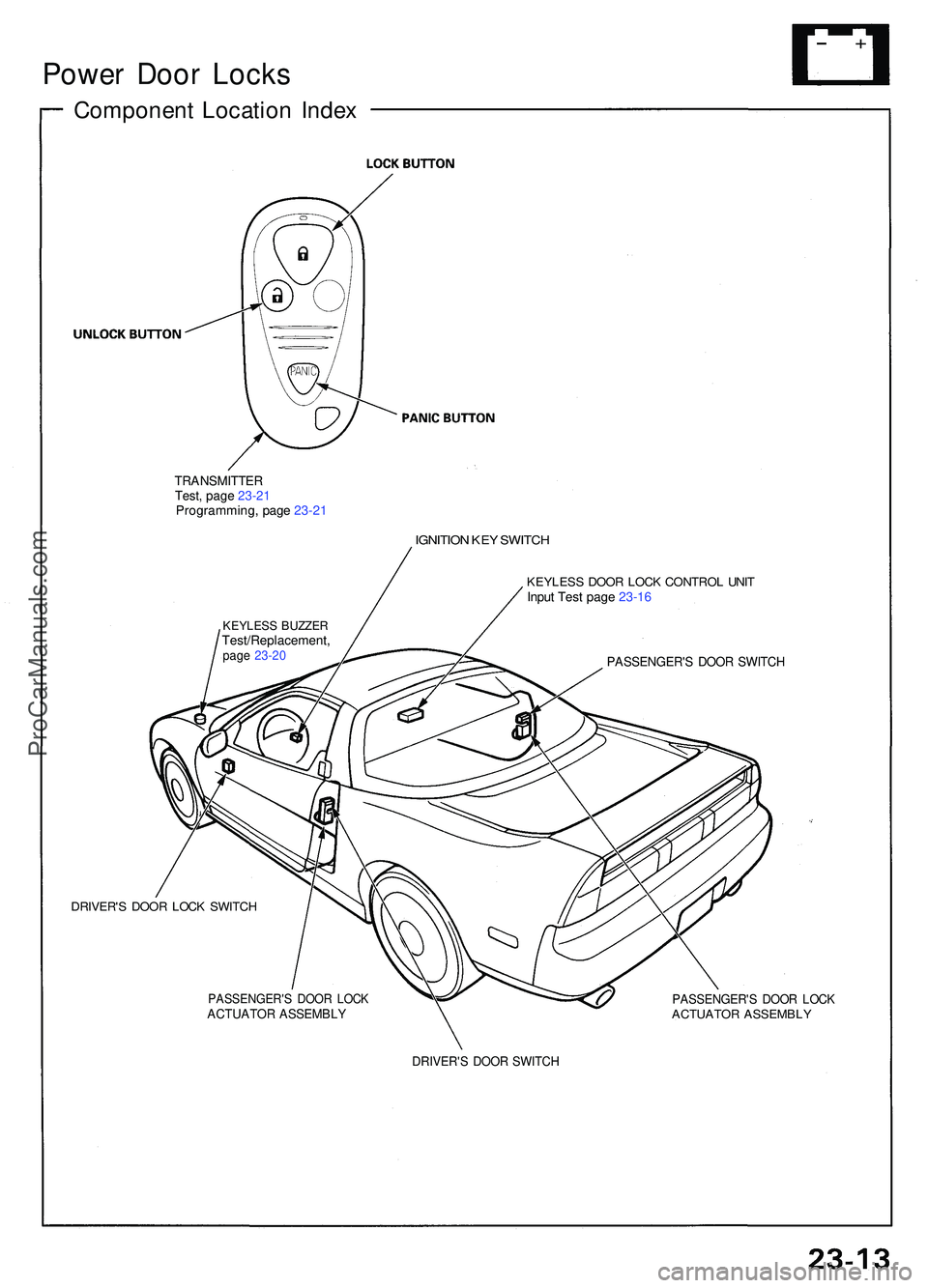
TRANSMITTE RTest, pag e 23-2 1Programming , pag e 23-2 1
IGNITIO N KE Y SWITC H
KEYLES S DOO R LOC K CONTRO L UNI TInput Tes t pag e 23-1 6
PASSENGER' S DOO R SWITC H
DRIVER' S DOO R LOC K SWITC H
PASSENGER' S DOO R LOC KACTUATO R ASSEMBL YPASSENGER' S DOO R LOC KACTUATO R ASSEMBL Y
DRIVER'S DOO R SWITC H
KEYLES S BUZZE RTest/Replacement ,page 23-2 0
ProCarManuals.com
Page 358 of 1503
Power Door Locks
Keyless Buzzer Test/Replacement
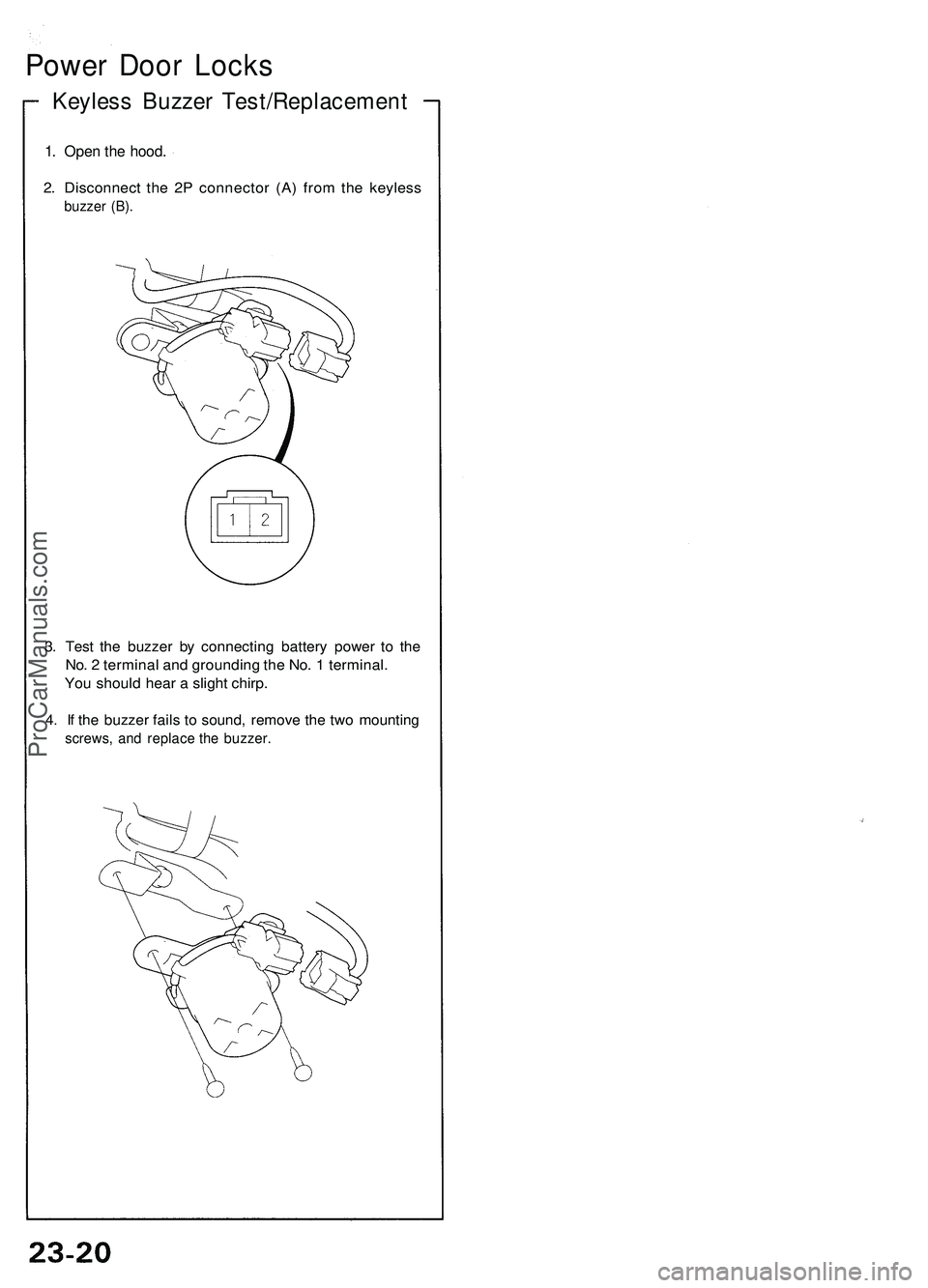
1. Open the hood.
2. Disconnect the 2P connector (A) from the keyless
buzzer (B).
3. Test the buzzer by connecting battery power to the
No. 2 terminal and grounding the No. 1 terminal.
You should hear a slight chirp.
4. If the buzzer fails to sound, remove the two mounting
screws, and replace the buzzer.ProCarManuals.com
Page 359 of 1503
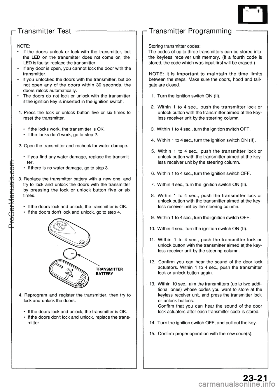
Transmitter Test
NOTE:
• If the doors unlock or lock with the transmitter, but
the LED on the transmitter does not come on, the
LED is faulty; replace the transmitter.
• If any door is open, you cannot lock the door with the
transmitter.
• If you unlocked the doors with the transmitter, but do
not open any of the doors within 30 seconds, the
doors relock automatically.
• The doors do not lock or unlock with the transmitter
if the ignition key is inserted in the ignition switch.
1. Press the lock or unlock button five or six times to
reset the transmitter.
• If the locks work, the transmitter is OK.
• If the locks don't work, go to step 2.
2. Open the transmitter and recheck for water damage.
• If you find any water damage, replace the transmit-
ter.
• If there is no water damage, go to step 3.
3. Replace the transmitter battery with a new one, and
try to lock and unlock the doors with the transmitter
by pressing the lock or unlock button five or six
times.
• If the doors lock and unlock, the transmitter is OK.
• If the doors don't lock and unlock, go to step 4.
4. Reprogram and register the transmitter, then try to
lock and unlock the doors.
• If the doors lock and unlock, the transmitter is OK.
• If the doors don't lock and unlock, replace the trans-
mitter
Transmitter Programming
Storing transmitter codes:
The codes of up to three transmitters can be stored into
the keyless receiver unit memory. (If a fourth code is
stored, the code which was input first will be erased.)
NOTE: It is important to maintain the time limits
between the steps. Make sure the doors, hood and tail-
gate are closed.
1. Turn the ignition switch ON (II).
2. Within 1 to 4 sec., push the transmitter lock or
unlock button with the transmitter aimed at the key-
less receiver unit by the steering column.
3. Within 1 to 4 sec., turn the ignition switch OFF.
4. Within 1 to 4 sec., turn the ignition switch ON (II).
5. Within 1 to 4 sec., push the transmitter lock or
unlock button with the transmitter aimed at the key-
less receiver unit by the steering column.
6. Within 1 to 4 sec., turn the ignition switch OFF.
7. Within 4 sec., turn the ignition switch ON (II).
8. Within 1 to 4 sec., push the transmitter lock or
unlock button with the transmitter aimed at the key-
less receiver unit by the steering column.
9. Within 1 to 4 sec., turn the ignition switch OFF.
10. Within 4 sec., turn the ignition switch ON (II).
11. Within 1 to 4 sec., push the transmitter lock or
unlock button with the transmitter aimed at the key-
less receiver unit by the steering column.
12. Confirm you can hear the sound of the door lock
actuators. Within 1 to 4 sec., push the transmitter
lock or unlock button again.
13. Within 10 sec., aim the transmitters (up to two addi-
tional ones) whose codes you want to store at the
keyless receiver unit, and press the transmitter lock
or unlock buttons.
Confirm that you can hear the sound of the door
lock actuators after each transmitter code is stored.
14. Turn the ignition switch OFF, and pull out the key.
15. Confirm proper operation with the new code(s).ProCarManuals.com
Page 435 of 1503
Timing Belt
Installation
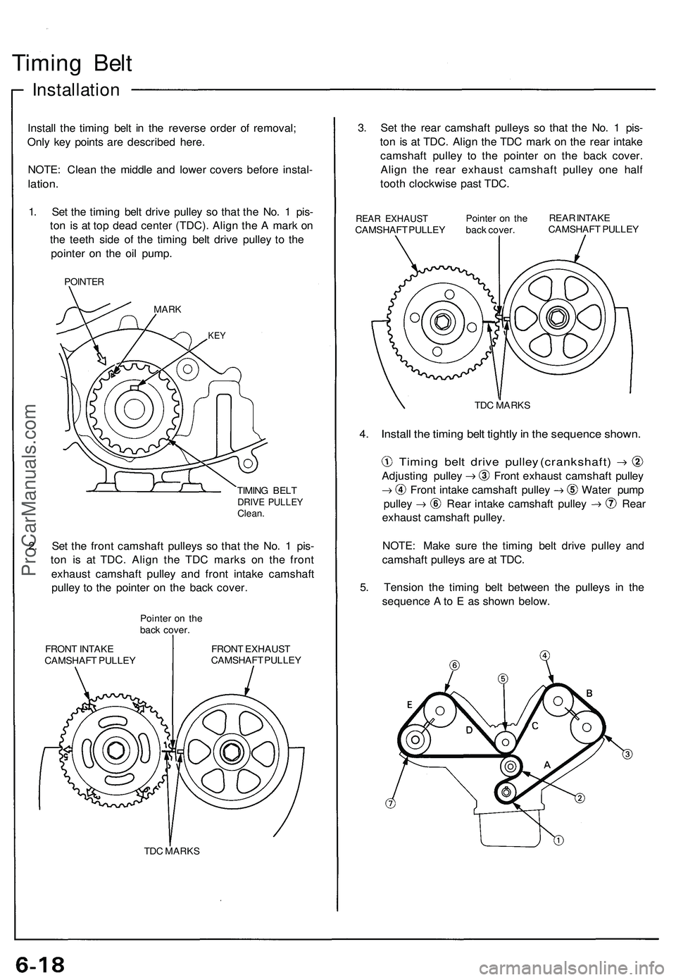
Install the timing belt in the reverse order of removal;
Only key points are described here.
NOTE: Clean the middle and lower covers before instal-
lation.
1. Set the timing belt drive pulley so that the No. 1 pis-
ton is at top dead center (TDC). Align the A mark on
the teeth side of the timing belt drive pulley to the
pointer on the oil pump.
POINTER
MARK
KEY
TIMING BELT
DRIVE PULLEY
Clean.
2. Set the front camshaft pulleys so that the No. 1 pis-
ton is at TDC. Align the TDC marks on the front
exhaust camshaft pulley and front intake camshaft
pulley to the pointer on the back cover.
Pointer on the
back cover.
FRONT INTAKE
CAMSHAFT PULLEY
FRONT EXHAUST
CAMSHAFT PULLEY
TDC MARKS
3. Set the rear camshaft pulleys so that the No. 1 pis-
ton is at TDC. Align the TDC mark on the rear intake
camshaft pulley to the pointer on the back cover.
Align the rear exhaust camshaft pulley one half
tooth clockwise past TDC.
REAR EXHAUST
CAMSHAFT PULLEY
Pointer on the
back cover.
REAR INTAKE
CAMSHAFT PULLEY
TDC MARKS
4. Install the timing belt tightly in the sequence shown.
Timing belt drive pulley (crankshaft)
Adjusting pulley Front exhaust camshaft pulley
Front intake camshaft pulley Water pump
pulley Rear intake camshaft pulley Rear
exhaust camshaft pulley.
NOTE: Make sure the timing belt drive pulley and
camshaft pulleys are at TDC.
5. Tension the timing belt between the pulleys in the
sequence A to E as shown below.ProCarManuals.com
Page 469 of 1503
Camshafts
Installation
CAUTION: Valve locknuts should be loosened and ad-
justing screws backed off before installation.
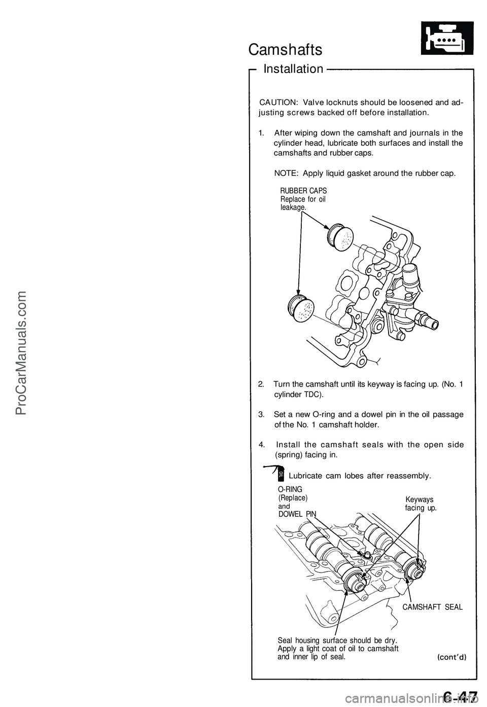
1. After wiping down the camshaft and journals in the
cylinder head, lubricate both surfaces and install the
camshafts and rubber caps.
NOTE: Apply liquid gasket around the rubber cap.
2. Turn the camshaft until its keyway is facing up. (No. 1
cylinder
TDC).
3. Set a new O-ring and a dowel pin in the oil passage
of the No. 1 camshaft holder.
4. Install the camshaft seals with the open side
(spring) facing in.
Lubricate cam lobes after reassembly.
O-RING
(Replace)
and
DOWEL PIN
Keyways
facing up.
CAMSHAFT SEAL
Seal housing surface should be dry.
Apply a light coat of oil to camshaft
and inner lip of seal.
RUBBER CAPS
Replace for oil
leakage.ProCarManuals.com
Page 482 of 1503
Crankshaft
Inspection
• Clea n th e crankshaf t oi l passage s wit h pip e
cleaner s o r a suitabl e brush .
• Chec k th e keywa y an d threads .
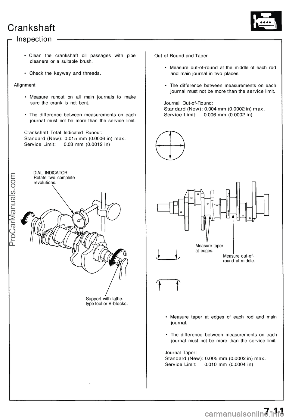
Alignmen t
• Measur e runou t o n al l mai n journal s t o mak e
sur e th e cran k i s no t bent .
• Th e differenc e betwee n measurement s o n eac h
journa l mus t no t b e mor e tha n th e servic e limit .
Crankshaf t Tota l Indicate d Runout :
Standard (New) : 0.01 5 m m (0.000 6 in ) max .
Servic e Limit : 0.0 3 m m (0.001 2 in )
DIA L INDICATO R
Rotat e tw o complet e
revolutions .
Support wit h lathe -type too l o r V-blocks .
Out-of-Roun d an d Tape r
• Measur e out-of-roun d a t th e middl e o f eac h ro d
and mai n journa l i n tw o places .
• Th e differenc e betwee n measurement s o n eac h
journa l mus t no t b e mor e tha n th e servic e limit .
Journa l Out-of-Round :
Standard (New) : 0.00 4 m m (0.000 2 in ) max .
Servic e Limit : 0.00 6 m m (0.000 2 in )
Measur e out-of -round a t middle .
• Measur e tape r a t edge s o f eac h ro d an d mai n
journal .
• Th e differenc e betwee n measurement s o n eac h
journa l mus t no t b e mor e tha n th e servic e limit .
Journa l Taper :
Standar d (New) : 0.00 5 m m (0.000 2 in ) max .
Servic e Limit : 0.01 0 m m (0.000 4 in )
Measur e tape rat edges .
ProCarManuals.com
Page 1241 of 1503
Battery
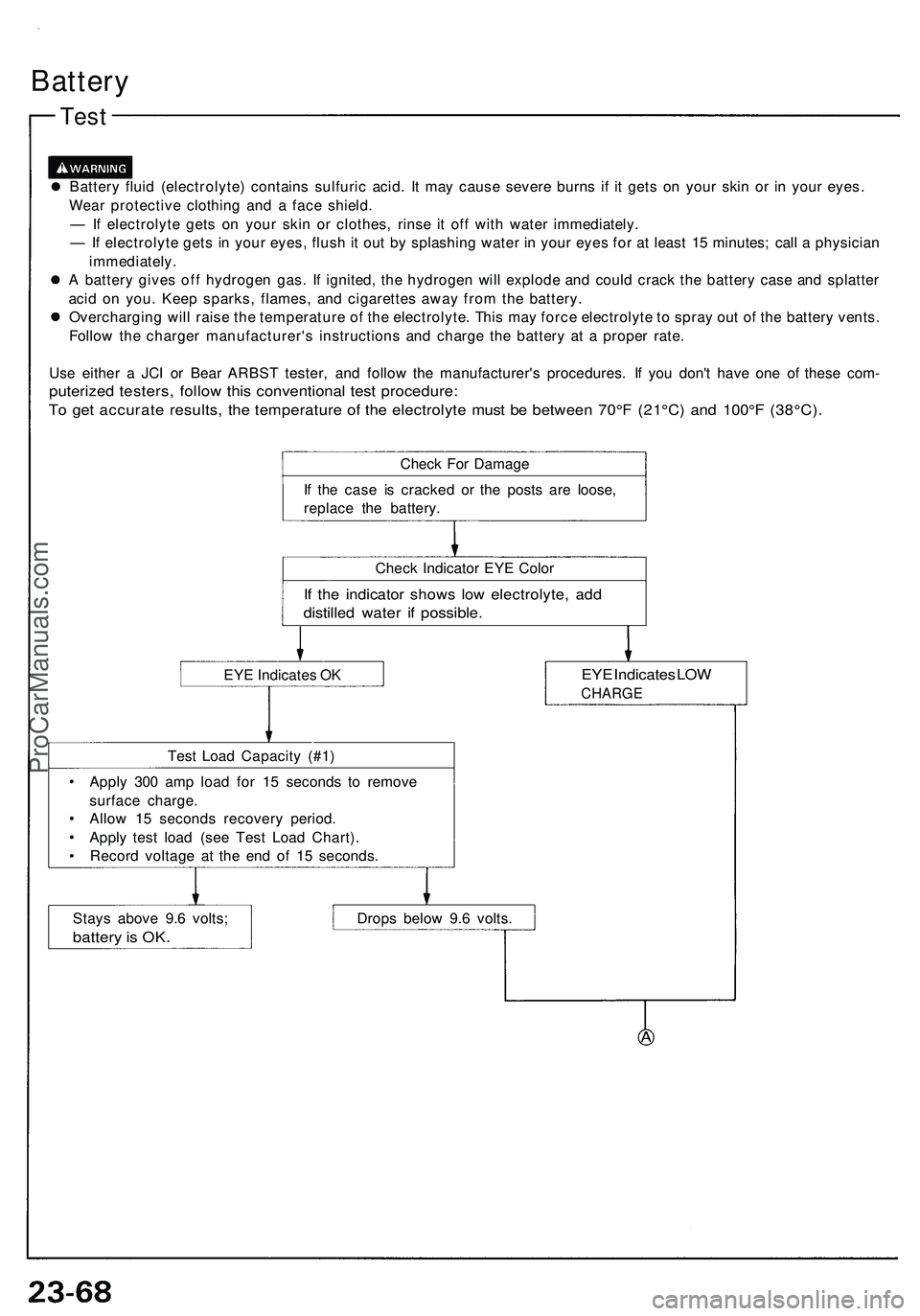
Test
Batter y flui d (electrolyte ) contain s sulfuri c acid . I t ma y caus e sever e burn s i f i t get s o n you r ski n o r i n you r eyes .
Wea r protectiv e clothin g an d a fac e shield .
— If electrolyt e get s o n you r ski n o r clothes , rins e i t of f wit h wate r immediately .
— If electrolyt e get s in you r eyes , flus h it ou t b y splashin g wate r i n you r eye s fo r a t leas t 1 5 minutes ; cal l a physicia n
immediately .
A batter y give s of f hydroge n gas. If ignited , th e hydroge n wil l explod e an d coul d crac k th e batter y cas e an d splatte r
aci d o n you . Kee p sparks , flames , an d cigarette s awa y fro m th e battery .
Overchargin g wil l rais e th e temperatur e o f th e electrolyte . Thi s ma y forc e electrolyt e t o spra y ou t o f th e batter y vents .
Follo w th e charge r manufacturer' s instruction s an d charg e th e batter y a t a prope r rate .
Us e eithe r a JC I o r Bea r ARBS T tester , an d follo w th e manufacturer' s procedures . I f yo u don' t hav e on e of thes e com -
puterize d testers , follo w thi s conventiona l tes t procedure :
To ge t accurat e results , th e temperatur e o f th e electrolyt e mus t b e betwee n 70° F (2 1°C ) an d 100° F (38°C) .
Check Fo r Damag e
I f th e cas e i s cracke d o r th e post s ar e loose ,
replac e th e battery .
Chec k Indicato r EY E Colo r
If th e indicato r show s low electrolyte , ad d
distille d wate r i f possible .
EYE Indicate s O KEY E Indicate s LO W
CHARG E
Test Loa d Capacit y (#1 )
Appl y 30 0 am p loa d fo r 1 5 second s t o remov e
surfac e charge .
Allo w 1 5 second s recover y period .
Appl y tes t loa d (se e Tes t Loa d Chart) .
Recor d voltag e a t th e en d o f 1 5 seconds .
Stay s abov e 9. 6 volts ;
batter y is OK .
Drop s belo w 9. 6 volts .
ProCarManuals.com
Page 1245 of 1503
Ignition Switch
Test
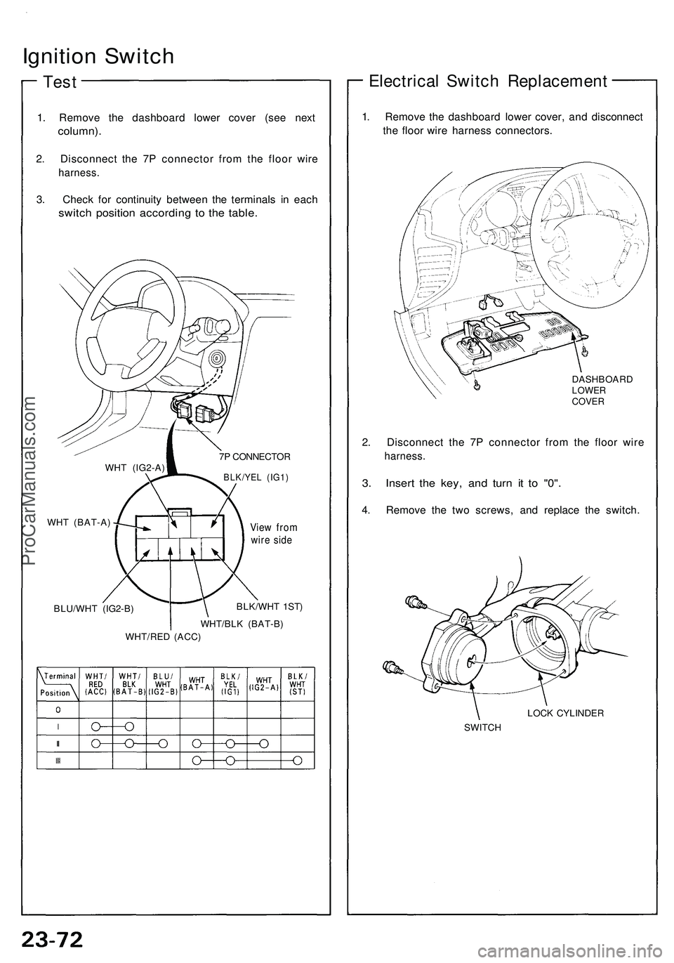
1. Remove the dashboard lower cover (see next
column).
2. Disconnect the 7P connector from the floor wire
harness.
3. Check for continuity between the terminals in each
switch position according to the table.
7P CONNECTOR
BLK/YEL (IG1)
BLU/WHT (IG2-B)
View from
wire side
BLK/WHT 1ST)
WHT/BLK (BAT-B)
WHT/RED (ACC)
Electrical Switch Replacement
1. Remove the dashboard lower cover, and disconnect
the floor wire harness connectors.
DASHBOARD
LOWER
COVER
2. Disconnect the 7P connector from the floor wire
harness.
3. Insert the key, and turn it to "0".
4. Remove the two screws, and replace the switch.
LOCK CYLINDER
SWITCH
WHT (IG2-A)
WHT (BAT-A)ProCarManuals.com