boot ACURA NSX 1997 Service Repair Manual
[x] Cancel search | Manufacturer: ACURA, Model Year: 1997, Model line: NSX, Model: ACURA NSX 1997Pages: 1503, PDF Size: 57.08 MB
Page 285 of 1503
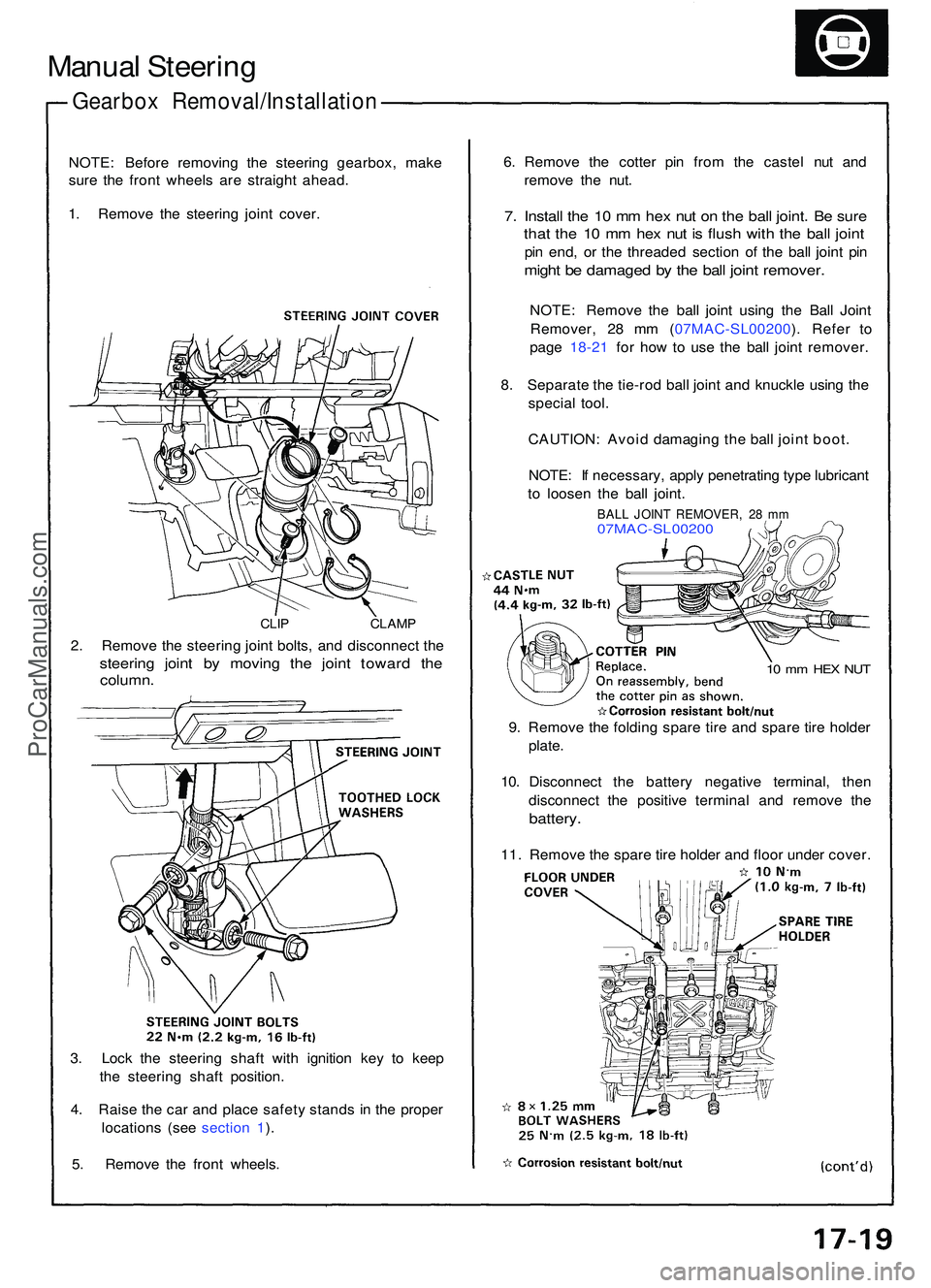
Manual Steerin g
Gearbo x Removal/Installatio n
NOTE: Befor e removin g th e steerin g gearbox , mak e
sur e th e fron t wheel s ar e straigh t ahead .
1 . Remov e th e steerin g join t cover .
CLIP CLAM P
2. Remov e th e steerin g join t bolts , an d disconnec t th e
steerin g join t b y movin g th e join t towar d th e
column .
3. Loc k th e steerin g shaf t wit h ignitio n ke y t o kee p
th e steerin g shaf t position .
4 . Rais e th e ca r an d plac e safet y stand s i n th e prope r
location s (se e sectio n 1 ).
5 . Remov e th e fron t wheels . 6
. Remov e th e cotte r pi n fro m th e caste l nu t an d
remov e th e nut .
7. Instal l th e 1 0 m m he x nu t o n th e bal l joint . B e sur e
that th e 1 0 m m he x nu t i s flus h wit h th e bal l join t
pin end , o r th e threade d sectio n o f th e bal l join t pi n
migh t b e damage d b y th e bal l join t remover .
NOTE: Remov e th e bal l join t usin g th e Bal l Join t
Remover , 2 8 m m ( 07MAC-SL00200 ). Refe r t o
pag e 18-2 1 fo r ho w to us e th e bal l join t remover .
8 . Separat e th e tie-ro d bal l join t an d knuckl e usin g th e
specia l tool .
CAUTION : Avoi d damagin g th e bal l join t boot .
NOTE : I f necessary , appl y penetratin g typ e lubrican t
t o loose n th e bal l joint .
BALL JOIN T REMOVER , 2 8 m m07MAC-SL0020 0
10 m m HE X NU T
9. Remov e th e foldin g spar e tir e an d spar e tir e holde r
plate .
10 . Disconnec t th e batter y negativ e terminal , the n
disconnec t th e positiv e termina l an d remov e th e
battery .
11. Remov e th e spar e tir e holde r an d floo r unde r cover .
ProCarManuals.com
Page 288 of 1503
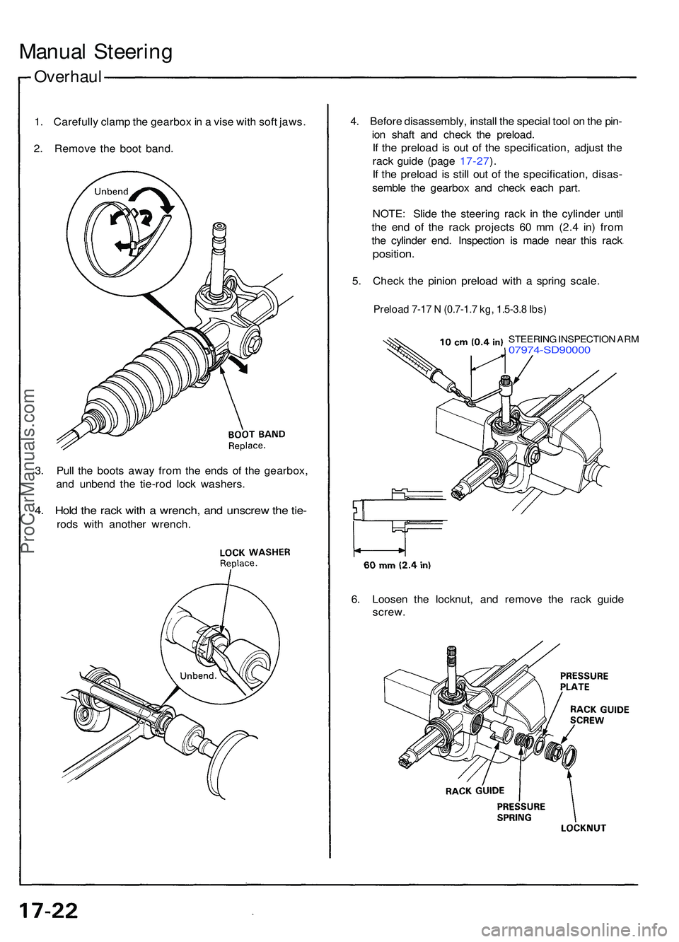
Overhaul
Manual Steerin g
1. Carefull y clam p th e gearbo x in a vis e wit h sof t jaws .
2 . Remov e th e boo t band . 4
. Befor e disassembly , instal l th e specia l too l o n th e pin -
io n shaf t an d chec k th e preload .
I f th e preloa d i s ou t o f th e specification , adjus t th e
rac k guid e (pag e 17-27 ).
I f th e preloa d i s stil l ou t o f th e specification , disas -
sembl e th e gearbo x an d chec k eac h part .
NOTE : Slid e th e steerin g rac k i n th e cylinde r unti l
th e en d o f th e rac k project s 6 0 m m (2. 4 in ) fro m
th e cylinde r end . Inspectio n i s mad e nea r thi s rac k
position .
5. Chec k th e pinio n preloa d wit h a sprin g scale .
Preload 7-17 N (0.7-1.7 kg, 1.5-3.8 Ibs)
STEERIN G INSPECTIO N AR M07974-SD9000 0
3. Pul l th e boot s awa y fro m th e end s o f th e gearbox ,
an d unben d th e tie-ro d loc k washers .
4. Hol d th e rac k wit h a wrench , an d unscre w th e tie -
rod s wit h anothe r wrench .
6. Loose n th e locknut , an d remov e th e rac k guid e
screw .
ProCarManuals.com
Page 294 of 1503
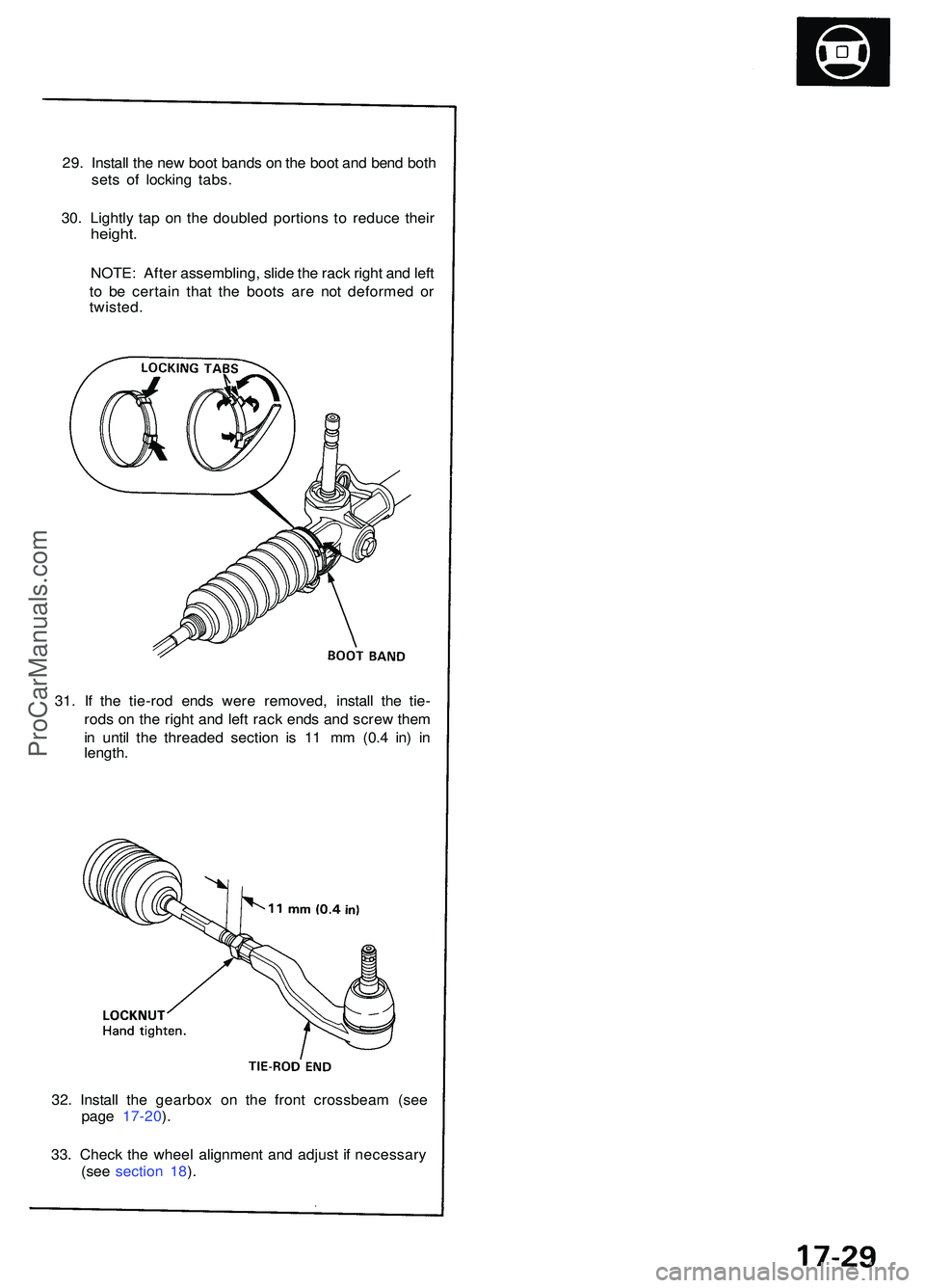
29. Instal l th e ne w boo t band s o n th e boo t an d ben d bot h
set s o f lockin g tabs .
30 . Lightl y ta p o n th e double d portion s t o reduc e thei r
height .
NOTE : Afte r assembling , slid e th e rac k righ t an d lef t
t o b e certai n tha t th e boot s ar e no t deforme d o r
twisted .
32 . Instal l th e gearbo x o n th e fron t crossbea m (se e
pag e 17-20 ).
33 . Chec k th e whee l alignmen t an d adjus t i f necessar y
(se e sectio n 18 ).
31
. I f th e tie-ro d end s wer e removed , instal l th e tie -
rod s o n th e righ t an d lef t rac k end s an d scre w the m
i n unti l th e threade d sectio n i s 1 1 m m (0. 4 in ) i n
length .
ProCarManuals.com
Page 295 of 1503
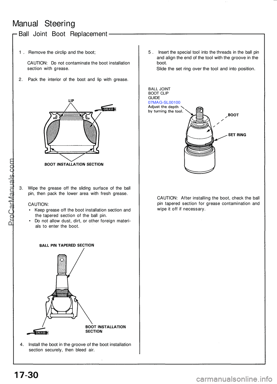
Ball Join t Boo t Replacemen t
Manual Steerin g
1 . Remov e th e circli p an d th e boot ;
CAUTION : D o no t contaminat e th e boo t installatio n
sectio n wit h grease .
2 . Pac k th e interio r o f th e boo t an d li p wit h grease . 5
. Inser t th e specia l too l int o th e thread s i n th e bal l pi n
and alig n th e en d o f th e too l wit h th e groov e in th e
boot .
Slide th e se t rin g ove r th e too l an d int o position .
BALL JOIN T
BOO T CLI P
GUID E07MAG-SL0010 0
3. Wip e th e greas e of f th e slidin g surfac e o f th e bal l
pin , the n pac k th e lowe r are a wit h fres h grease .
CAUTION :
• Kee p greas e of f th e boo t installatio n sectio n an d
th e tapere d sectio n o f th e bal l pin .
• D o no t allo w dust , dirt , o r othe r foreig n materi -
al s t o ente r th e boot . CAUTION
: Afte r installin g th e boot , chec k th e bal l
pi n tapere d sectio n fo r greas e contaminatio n an d
wip e i t of f i f necessary .
4. Instal l th e boo t i n th e groov e o f th e boo t installatio n
section securely , the n blee d air .
ProCarManuals.com
Page 371 of 1503
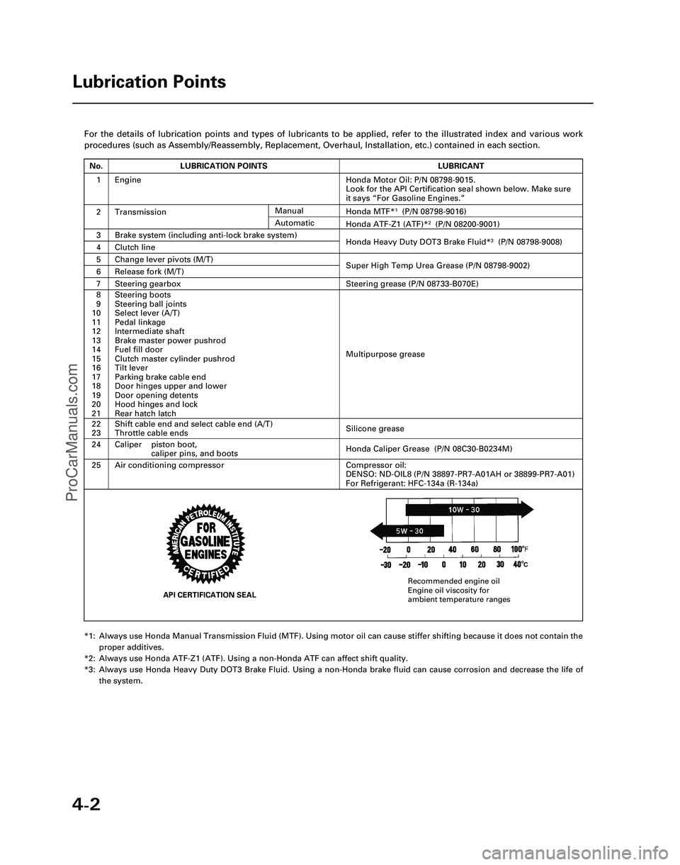
4-2
For the details of lubrication points and types of lubricants to be appl\
ied, refer to the illustrated index and various work
procedures (such as Assembly/Reassembly, Replacement, Overhaul, Install\
ation, etc.) contained in each section.
*1: Always use Honda Manual Transmission Fluid (MTF). Using motor oil can \
cause stiffer shifting because it does not contain theproper additives.
*2: Always use Honda ATF-Z1 (ATF). Using a non-Honda ATF can affect shift \
quality.
*3: Always use Honda Heavy Duty DOT3 Brake Fluid. Using a non-Honda brake fl\
uid can cause corrosion and decrease the life of the system.
Lubrication Points
No.LUBRICATION POINTSLUBRICANT
1Honda Motor Oil: P/N 08798-9015.
Look for the API Certification seal shown below. Make sure
it says “For Gasoline Engines.”
2TransmissionHonda MTF*1(P/N 08798-9016)
3Brake system (including anti-lock brake system)Honda Heavy Duty DOT3 Brake Fluid*3(P/N 08798-9008)4Clutch line
5Change lever pivots (M/T)Super High Temp Urea Grease (P/N 08798-9002)6Release fork (M/T)
8
9
10
11
12
13
14
15
16
17
18
19
20
21Steering boots
Steering ball joints
Select lever (A/T)
Pedal linkage
Intermediate shaft
Brake master power pushrod
Fuel fill door
Clutch master cylinder pushrod
Tilt lever
Parking brake cable end
Door hinges upper and lower
Door opening detents
Hood hinges and lock
Rear hatch latch
Multipurpose grease
24
22
23
Caliper piston boot, caliper pins, and boots
Shift cable end and select cable end (A/T)
Throttle cable ends
Honda Caliper Grease (P/N 08C30-B0234M)
Silicone grease
25Air conditioning compressorCompressor oil:
DENSO: ND-OIL8 (P/N 38897-PR7-A01AH or 38899-PR7-A01)
For Refrigerant: HFC-134a (R-134a)
Manual
Honda ATF-Z1 (ATF)*2(P/N 08200-9001)Automatic
7Steering gearboxSteering grease (P/N 08733-B070E)
Engine
API CERTIFICATION SEAL
Recommended engine oil
Engine oil viscosity for
ambient temperature ranges
*05-NSX (61SW004)SEC04(01-10) 9/22/04 1:49 PM Page 4-2
ProCarManuals.com
Page 374 of 1503
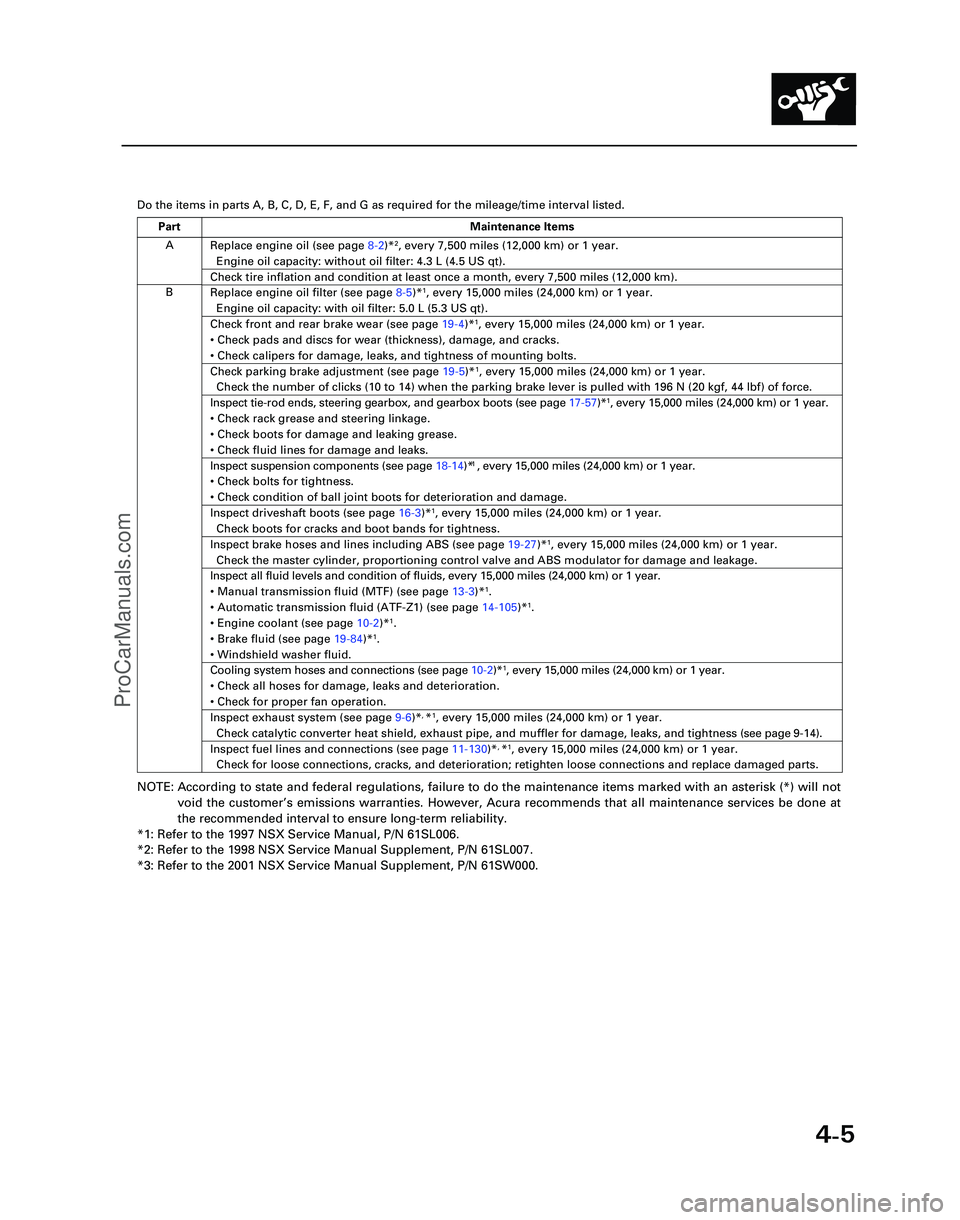
4-5
Y
Do the items in parts A, B, C, D, E, F, and G as required for the mileag\
e/time interval listed.
NOTE: According to state and federal regulations, failure to do the maintenanc\
e items marked with an asterisk (*) will not
void the customer ’s emissions warranties. However, Acura recommends that all maintenance s\
ervices be done at
the recommended interval to ensure long-term reliability.
*1: Refer to the 1997 NSX Service Manual, P/N 61SL006.
*2: Refer to the 1998 NSX Service Manual Supplement, P/N 61SL007.
*3: Refer to the 2001 NSX Service Manual Supplement, P/N 61SW000.
A
B Replace engine oil (see page
8-2)*
2, every 7,500 miles (12,000 km) or 1 year.
Engine oil capacity: without oil filter: 4.3 L (4.5 US qt).
Check tire inflation and condition at least once a month, every 7,500 mi\
les (12,000 km).
Replace engine oil filter (see page 8-5)*1, every 15,000 miles (24,000 km) or 1 year.
Engine oil capacity: with oil filter: 5.0 L (5.3 US qt).
Check front and rear brake wear (see page 19-4)*1, every 15,000 miles (24,000 km) or 1 year.
• Check pads and discs for wear (thickness), damage, and cracks.
• Check calipers for damage, leaks, and tightness of mounting bolts.
Check parking brake adjustment (see page 19-5)*1, every 15,000 miles (24,000 km) or 1 year.
Check the number of clicks (10 to 14) when the parking brake lever is pulled with 196 N (20 kgf,\
44 lbf) of force.
Inspect tie-rod ends, steering gearbox, and gearbox boots (see page 17-57)*1, every 15,000 miles (24,000 km) or 1 year.
• Check rack grease and steering linkage.
• Check boots for damage and leaking grease.
• Check fluid lines for damage and leaks.1
• Check bolts for tightness.
• Check condition of ball joint boots for deterioration and damage.
Inspect driveshaft boots (see page 16-3)*1, every 15,000 miles (24,000 km) or 1 year.
Check boots for cracks and boot bands for tightness.
Inspect brake hoses and lines including ABS (see page 19-27)*1, every 15,000 miles (24,000 km) or 1 year.
Check the master cylinder, proportioning control valve and ABS modulator\
for damage and leakage.
Inspect all fluid levels and condition of fluids, every 15,000 miles (2\
4,000 km) or 1 year.
• Manual transmission fluid (MTF) (see page 13-3)*
1.
• Automatic transmission fluid (ATF-Z1) (see page 14-105)*1.
• Engine coolant (see page 10-2)*1.
• Brake fluid (see page 19-84)*1.
• Windshield washer fluid.
Cooling system hoses and connections (see page 10-2)*1, every 15,000 miles (24,000 km) or 1 year.
• Check all hoses for damage, leaks and deterioration.
• Check for proper fan operation.
Inspect exhaust system (see page 9-6)*, *1, every 15,000 miles (24,000 km) or 1 year.
Check catalytic converter heat shield, exhaust pipe, and muffler for dam\
age, leaks, and tightness ( see page 9-14 ).
Inspect fuel lines and connections (see page 11-130)*, *1, every 15,000 miles (24,000 km) or 1 year.
Check for loose connections, cracks, and deterioration; retighten loose \
connections and replace damaged parts.
Part Maintenance Items
*05-NSX (61SW004)SEC04(01-10) 9/22/04 1:49 PM Page 4-5
Inspect suspension components (see page 18-14)* , every 15,000 miles (24,000 km) or 1 year.
ProCarManuals.com
Page 876 of 1503
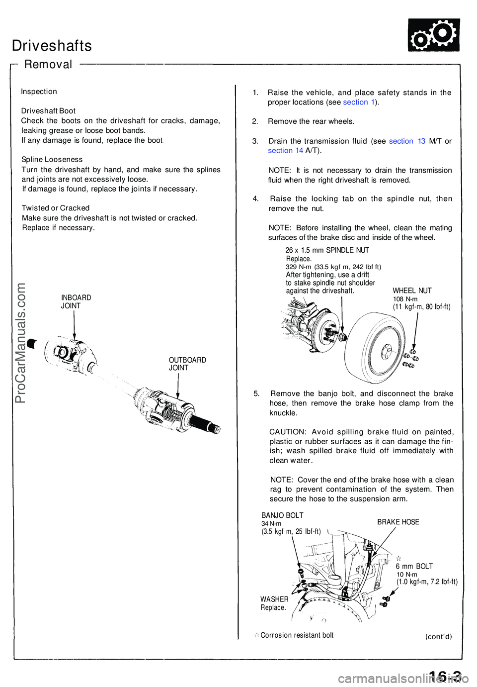
Driveshafts
Inspection
Driveshaf t Boo t
Chec k th e boot s o n th e driveshaf t fo r cracks , damage ,
leakin g greas e o r loos e boo t bands .
I f an y damag e i s found , replac e th e boo t
Splin e Loosenes s
Turn th e driveshaf t b y hand , an d mak e sur e th e spline s
an d joint s ar e no t excessivel y loose .
I f damag e is found , replac e th e joint s i f necessary .
Twiste d o r Cracked
Mak e sur e th e driveshaf t i s not twiste d o r cracked .
Replace i f necessary .
INBOARDJOINT
OUTBOAR DJOINT
1. Rais e th e vehicle , an d plac e safet y stand s i n th e
prope r location s (se e sectio n 1 ).
2 . Remov e th e rea r wheels .
3 . Drai n th e transmissio n flui d (se e sectio n 1 3 M/ T o r
sectio n 1 4 A/T) .
NOTE : I t i s no t necessar y t o drai n th e transmissio n
flui d whe n th e righ t driveshaf t i s removed .
4 . Rais e th e lockin g ta b o n th e spindl e nut , the n
remov e th e nut .
NOTE : Befor e installin g th e wheel , clea n th e matin g
surface s o f th e brak e dis c an d insid e o f th e wheel .
26 x 1. 5 m m SPINDL E NU TReplace .329 N- m (33. 5 kgf m , 24 2 Ib f ft )Afte r tightening , us e a drif tto stak e spindl e nu t shoulde ragainst th e driveshaft . WHEE L NU T108 N- m(11 kgf-m , 8 0 Ibf-ft )
5. Remov e th e banj o bolt , an d disconnec t th e brak e
hose , the n remov e th e brak e hos e clam p fro m th e
knuckle .
CAUTION : Avoi d spillin g brak e flui d o n painted ,
plasti c o r rubbe r surface s a s i t ca n damag e th e fin -
ish ; was h spille d brak e flui d of f immediatel y wit h
clea n water .
NOTE : Cove r th e en d o f th e brak e hos e wit h a clea n
ra g t o preven t contaminatio n o f th e system . The n
secur e th e hos e t o th e suspensio n arm .
BANJ O BOL T34 N-m(3.5 kg f m , 2 5 Ibf-ft )
WASHE RReplace .
Corrosio n resistan t bol t
BRAK E HOS E
6 m m BOL T10 N- m(1.0 kgf-m , 7. 2 Ibf-ft )
Remova l
ProCarManuals.com
Page 879 of 1503
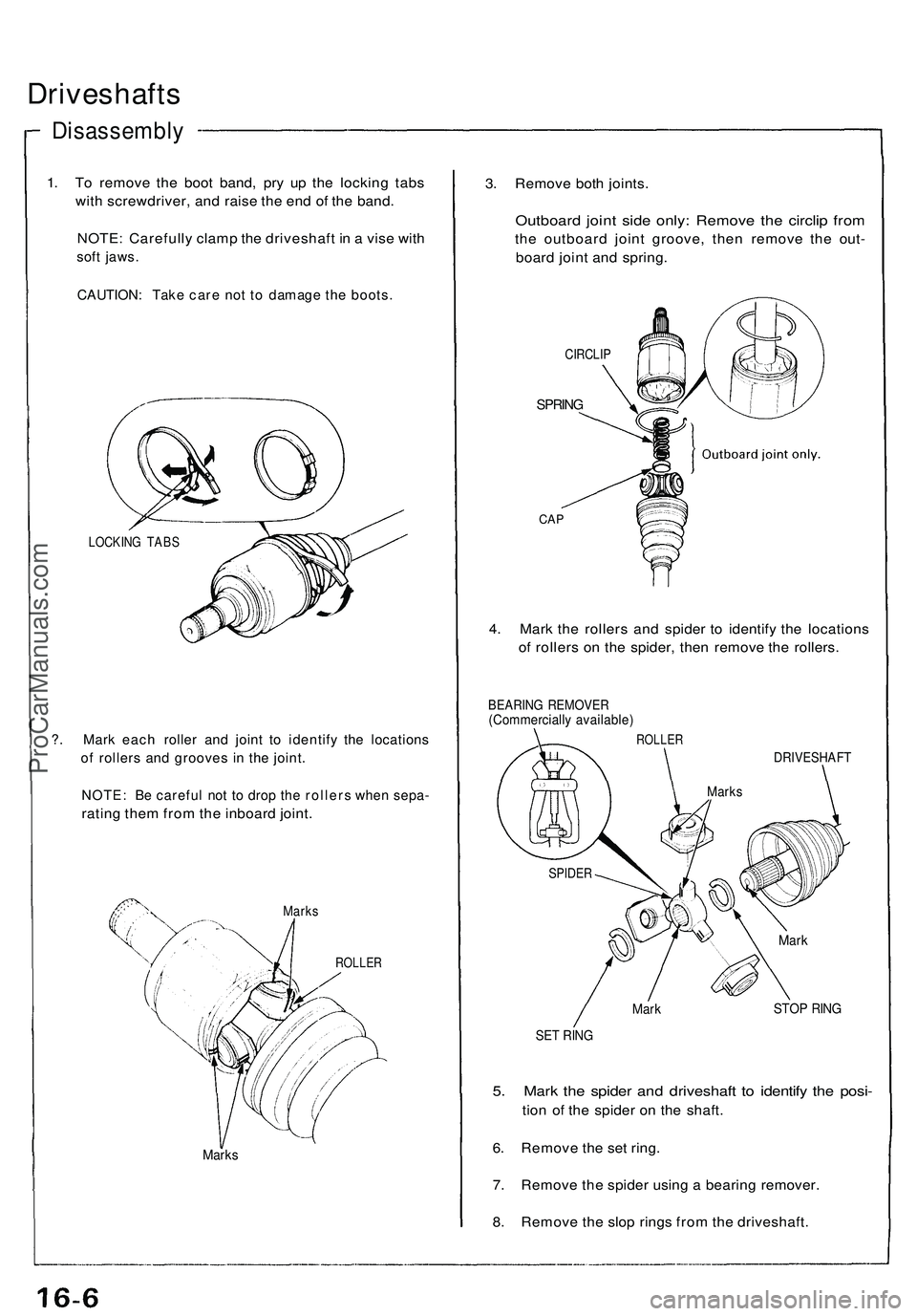
Driveshafts
Disassembly
1. To remove the boot band, pry up the locking tabs
with screwdriver, and raise the end of the band.
NOTE: Carefully clamp the driveshaft in a vise with
soft jaws.
CAUTION: Take care not to damage the boots.
LOCKING TABS
?. Mark each roller and joint to identify the locations
of rollers and grooves in the joint.
NOTE: Be careful not to drop the rollers when sepa-
rating them from the inboard joint.
Marks
ROLLER
Marks
3. Remove both joints.
Outboard joint side only: Remove the circlip from
the outboard joint groove, then remove the out-
board joint and spring.
CIRCLIP
SPRING
CAP
4. Mark the rollers and spider to identify the locations
of rollers on the spider, then remove the rollers.
BEARING REMOVER
(Commercially available)
ROLLER
DRIVESHAFT
Mark
STOP RING
SET RING
5. Mark the spider and driveshaft to identify the posi-
tion of the spider on the shaft.
6. Remove the set ring.
7. Remove the spider using a bearing remover.
8. Remove the slop rings from the driveshaft.
SPIDER
Marks
MarkProCarManuals.com
Page 880 of 1503
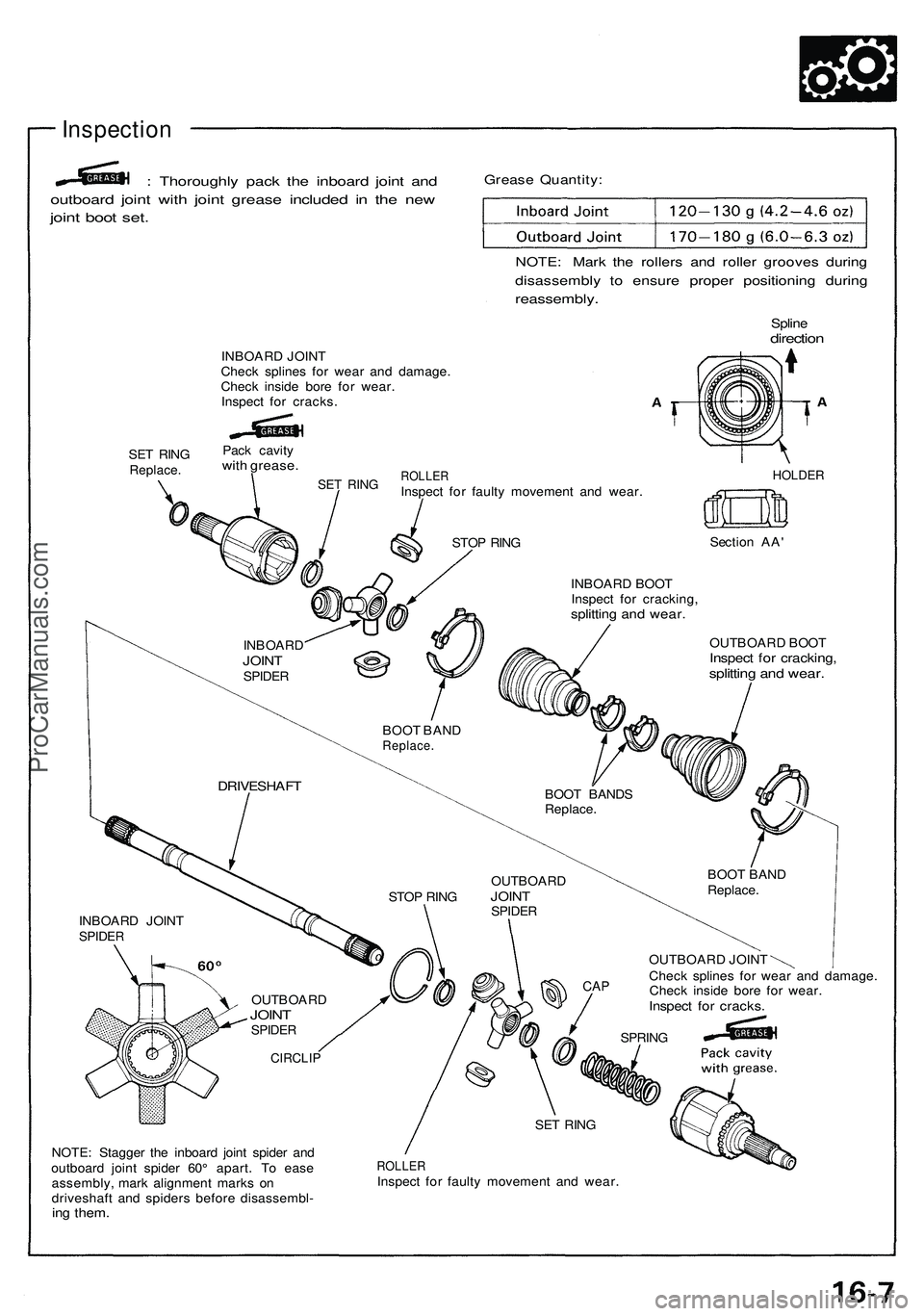
Inspection
: Thoroughl y pac k th e inboar d join t an d
outboar d join t wit h join t greas e include d i n th e ne w
joint boo t set .
Greas e Quantity :
NOTE: Mar k th e roller s an d rolle r groove s durin g
disassembl y t o ensur e prope r positionin g durin g
reassembly .
Splinedirectio n
INBOAR D JOIN T
Chec k spline s fo r wea r an d damage .
Chec k insid e bor e fo r wear .
Inspec t fo r cracks .
SE T RIN G
Replace .
Pack cavit ywith grease .
SET RIN GROLLE RInspect fo r fault y movemen t an d wear .HOLDE R
STOP RIN G Sectio
n AA '
INBOAR D BOO T
Inspec t fo r cracking ,
splitting an d wear .
OUTBOAR D BOO TInspec t fo r cracking ,splitting an d wear .
OUTBOAR D JOIN T
Chec k spline s fo r wea r an d damage .
Chec k insid e bor e fo r wear .
Inspec t fo r cracks .
NOTE: Stagge r th e inboar d join t spide r an d
outboar d join t spide r 60 ° apart . T o eas e
assembly , mar k alignmen t mark s o n
driveshaf t an d spider s befor e disassembl -
ing them .
ROLLE RInspect fo r fault y movemen t an d wear .
INBOAR
D
JOINTSPIDE R
BOOT BAN DReplace .
BOOT BAND S
Replace .
BOOT BAN D
Replace .
DRIVESHAF T
STOP RIN G OUTBOAR
DJOINTSPIDE R
CAP
SPRIN G
SE T RIN G
CIRCLI P
OUTBOAR DJOINTSPIDE R
INBOAR D JOIN TSPIDE R
ProCarManuals.com
Page 881 of 1503
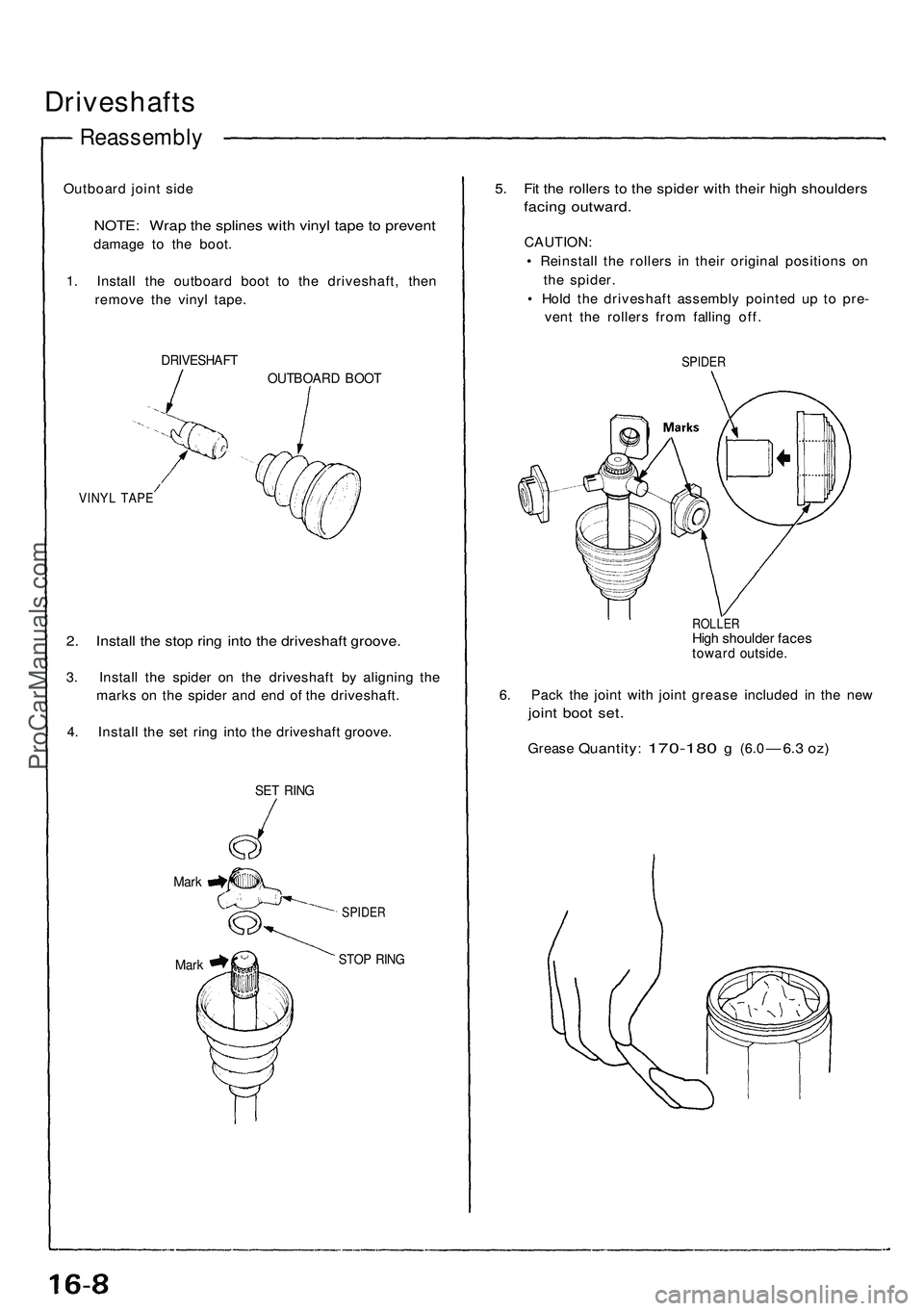
Driveshafts
Reassembly
Outboard joint side
NOTE: Wrap the splines with vinyl tape to prevent
damage to the boot.
1. Install the outboard boot to the driveshaft, then
remove the vinyl tape.
DRIVESHAFT
OUTBOARD BOOT
VINYL TAPE
2. Install the stop ring into the driveshaft groove.
3. Install the spider on the driveshaft by aligning the
marks on the spider and end of the driveshaft.
4. Install the set ring into the driveshaft groove.
SET RING
Mark
Mark
SPIDER
STOP RING
5. Fit the rollers to the spider with their high shoulders
facing outward.
CAUTION:
• Reinstall the rollers in their original positions on
the spider.
• Hold the driveshaft assembly pointed up to pre-
vent the rollers from falling off.
SPIDER
ROLLER
High shoulder faces
toward outside.
6. Pack the joint with joint grease included in the new
joint boot set.
Grease
Quantity:
170-180
g
(6.0
— 6.3 oz)ProCarManuals.com