brakes ACURA NSX 1997 Service Repair Manual
[x] Cancel search | Manufacturer: ACURA, Model Year: 1997, Model line: NSX, Model: ACURA NSX 1997Pages: 1503, PDF Size: 57.08 MB
Page 1 of 1503
General Info
Specifications
Maintenance
Engine
Cooling
Fuel and Emissions
*Transaxle
SteeringSuspension
*Brakes (Including ABS)
*Body
*Heating, Ventilation and
Air Conditioning
*Body Electrical
*Engine Electrical
*SRS
1997-200 5 NSX Main Menu
As sections w/ * include SRS components,
special precautions are required when servicing.
ProCarManuals.com
Page 370 of 1503
3-15
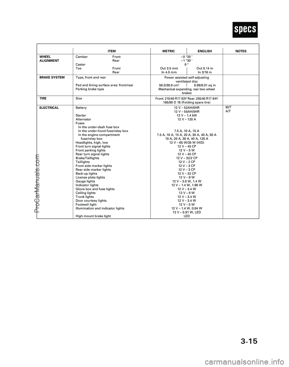
T
ITEMMETRICENGLISH
ELECTRICALBattery
Starter
Alternator
Fuses
In the under-dash fuse box
In the under-hood fuse/relay box
In the engine compartment
fuse/relay box
Headlights, high, low
Front turn signal lights
Front parking lights
Rear turn signal lights
Brake/Taillights
Taillights
Front side marker lights
Rear side marker lights
Back-up lights
License plate lights
Gauge lights
Indicator lights
Glove box and fuse lights
Ceiling lights
Trunk lights
Door courtesy lights
Footwell light
Illumination and indicator lights
High mount brake light12 V – 52AH/5HR
12 V – 55AH/5HR
12 V – 1.4 kW
12 V – 120 A
7.5 A, 10 A, 15 A
7.5 A, 10 A, 15 A, 20 A, 30 A, 40 A, 50 A
10 A, 20 A, 30 A, 40 A, 120 A
12 V – 65 W/35 W (HID)
12 V – 45 CP
12 V – 5 W
12 V – 45 CP
12 V – 32/2 CP
12 V – 2 CP
12 V – 3 CP
12 V – 3 CP
12 V – 32 CP
12 V – 8 W
12 V – 3.0 W, 1.4 W
12 V – 1.4 W, 1.96 W
12 V – 3.4 W
12 V – 8 W
12 V – 3.4 W
12 V – 3.4 W
12 V – 5 W
12 V – 1.4 W, 0.84 W
12 V – 0.91 W, LED
LED
TIRE
M/T
A/T
BRAKE SYSTEM
Front: 215/40 R17 83Y Rear: 255/40 R17 94Y165/80 D 16 (Folding spare tire)
Power assisted self-adjusting
ventilated disc
58.0/38.8 cm
28.99/6.01 sq in
Mechanical expanding, rear two wheel
brakes
WHEEL
ALIGNMENTCamber Front
Rear
Caster
Toe Front
Rear–0 °20 ’
–1 °30 ’
8 °
Out 3.5 mm Out 0.14 in
In 4.0 mm In 3/16 in
NOTES
Size
Type, front and rear
Pad and lining surface area: front/rear
Parking brake type
*04-NSX (61SW004)SEC03(01-16) 9/22/04 1:49 PM Page 3-15
ProCarManuals.com
Page 982 of 1503
Inspection and Adjustment
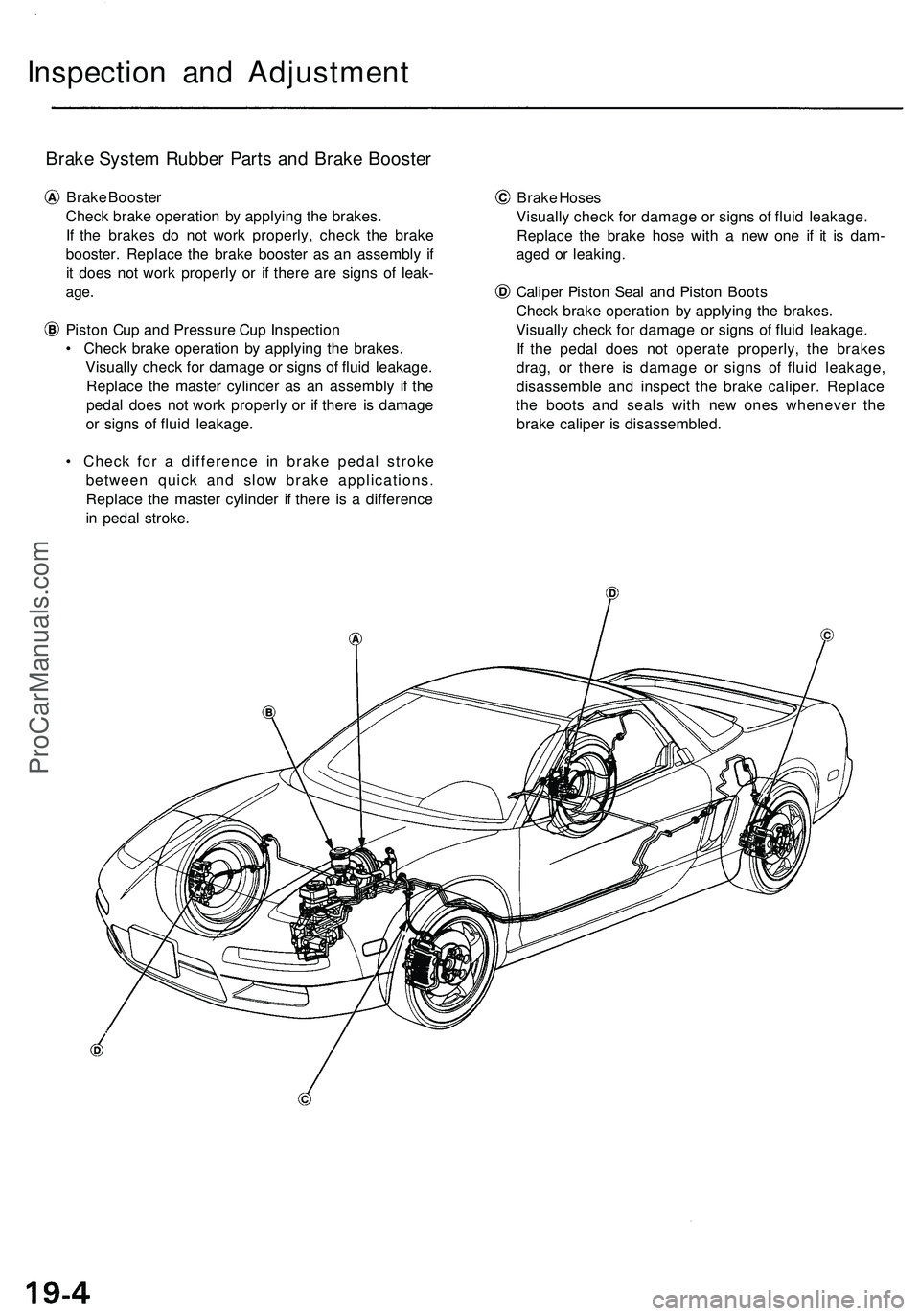
Brake System Rubber Parts and Brake Booster
Brake Booster
Check brake operation by applying the brakes.
If the brakes do not work properly, check the brake
booster. Replace the brake booster as an assembly if
it does not work properly or if there are signs of leak-
age.
Piston Cup and Pressure Cup Inspection
• Check brake operation by applying the brakes.
Visually check for damage or signs of fluid leakage.
Replace the master cylinder as an assembly if the
pedal does not work properly or if there is damage
or signs of fluid leakage.
• Check for a difference in brake pedal stroke
between quick and slow brake applications.
Replace the master cylinder if there is a difference
in pedal stroke.
Brake Hoses
Visually check for damage or signs of fluid leakage.
Replace the brake hose with a new one if it is dam-
aged or leaking.
Caliper Piston Seal and Piston Boots
Check brake operation by applying the brakes.
Visually check for damage or signs of fluid leakage.
If the pedal does not operate properly, the brakes
drag, or there is damage or signs of fluid leakage,
disassemble and inspect the brake caliper. Replace
the boots and seals with new ones whenever the
brake caliper is disassembled.ProCarManuals.com
Page 984 of 1503
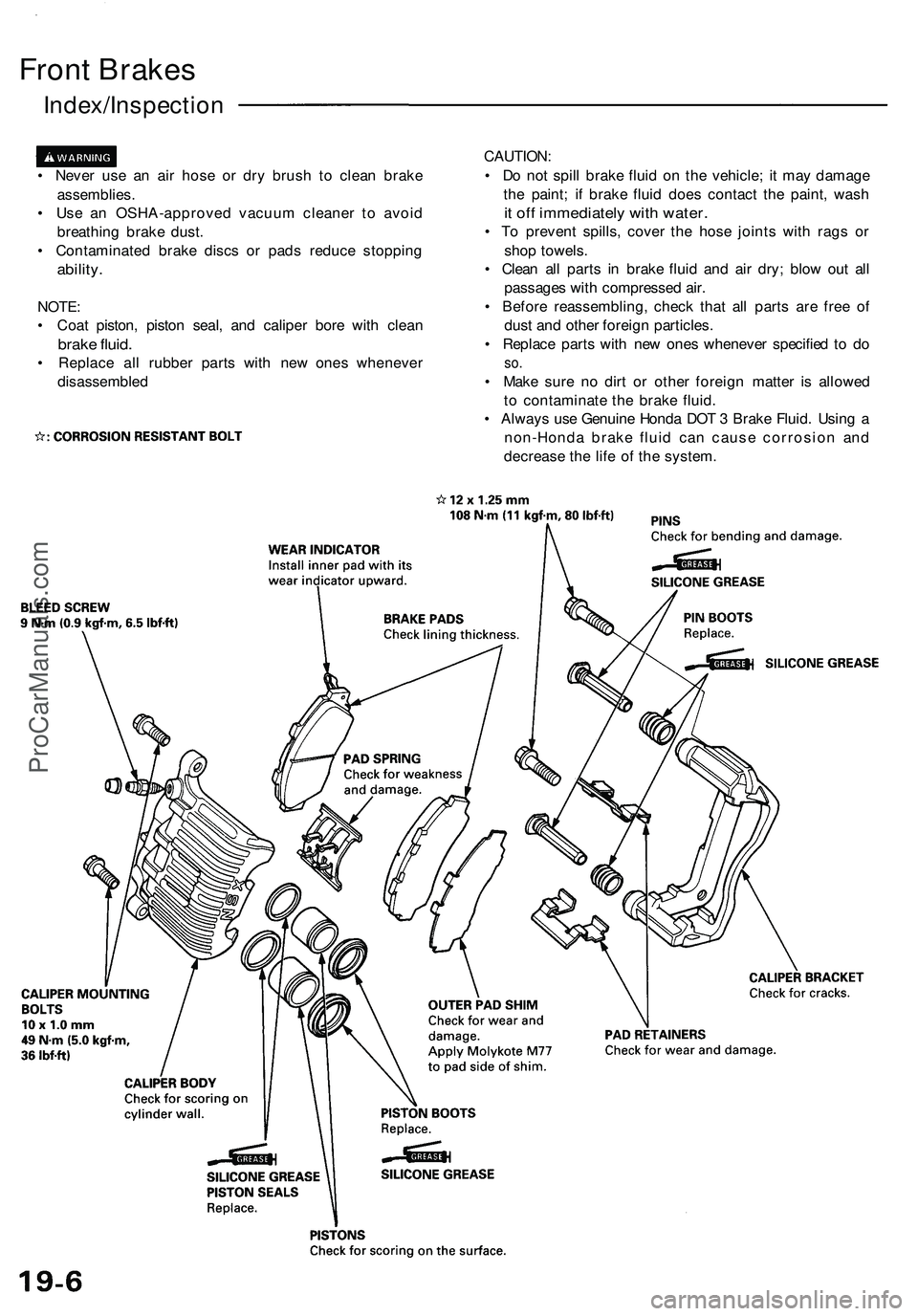
Front Brakes
Index/Inspection
• Never use an air hose or dry brush to clean brake
assemblies.
• Use an OSHA-approved vacuum cleaner to avoid
breathing brake dust.
• Contaminated brake discs or pads reduce stopping
ability.
NOTE:
• Coat piston, piston seal, and caliper bore with clean
brake fluid.
• Replace all rubber parts with new ones whenever
disassembled
CAUTION:
• Do not spill brake fluid on the vehicle; it may damage
the paint; if brake fluid does contact the paint, wash
it off immediately with water.
• To prevent spills, cover the hose joints with rags or
shop towels.
• Clean all parts in brake fluid and air dry; blow out all
passages with compressed air.
• Before reassembling, check that all parts are free of
dust and other foreign particles.
• Replace parts with new ones whenever specified to do
so.
• Make sure no dirt or other foreign matter is allowed
to contaminate the brake fluid.
• Always use Genuine Honda DOT 3 Brake Fluid. Using a
non-Honda brake fluid can cause corrosion and
decrease the life of the system.ProCarManuals.com
Page 996 of 1503
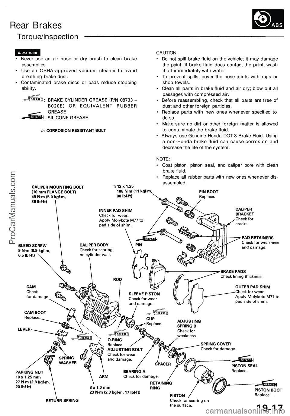
Rear Brakes
Torque/Inspection
• Never use an air hose or dry brush to clean brake
assemblies.
• Use an OSHA-approved vacuum cleaner to avoid
breathing brake dust.
• Contaminated brake discs or pads reduce stopping
ability.
CAUTION:
• Do not spill brake fluid on the vehicle; it may damage
the paint; if brake fluid does contact the paint, wash
it off immediately with water.
• To prevent spills, cover the hose joints with rags or
shop towels.
• Clean all parts in brake fluid and air dry; blow out all
passages with compressed air.
• Before reassembling, check that all parts are free of
dust and other foreign particles.
• Replace parts with new ones whenever specified to
do so.
• Make sure no dirt or other foreign matter is allowed
to contaminate the brake fluid.
• Always use Genuine Honda DOT 3 Brake Fluid. Using
a non-Honda brake fluid can cause corrosion and
decrease the life of the system.
NOTE:
• Coat piston, piston seal, and caliper bore with clean
brake fluid.
• Replace all rubber parts with new ones whenever dis-
assembled.ProCarManuals.com
Page 999 of 1503
Inspection/Replacement (cont'd)
Rear Brake Pads
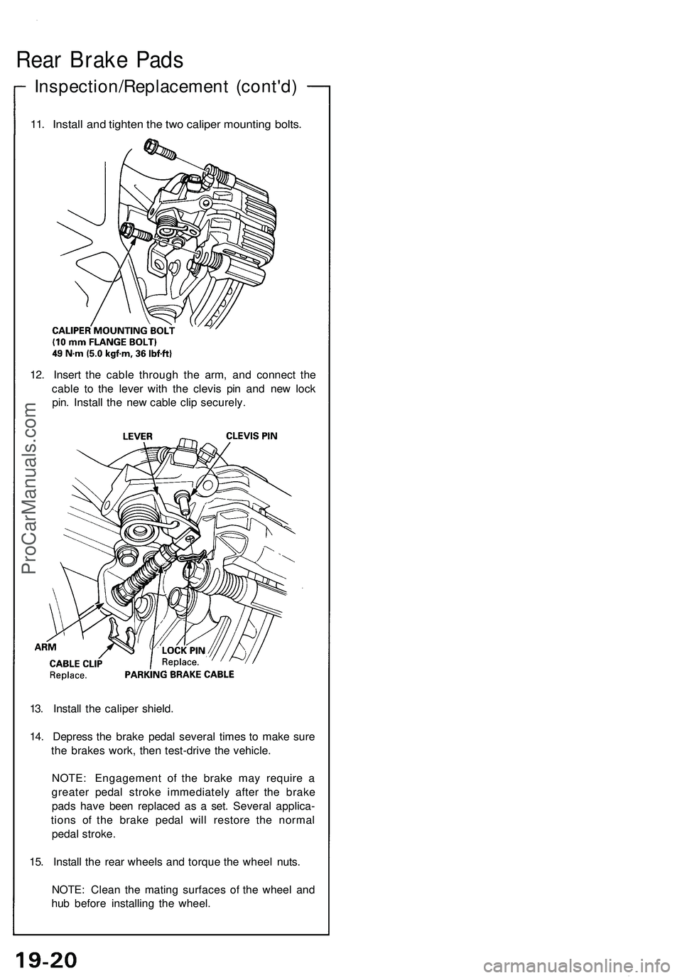
11. Install and tighten the two caliper mounting bolts.
12. Insert the cable through the arm, and connect the
cable to the lever with the clevis pin and new lock
pin. Install the new cable clip securely.
13. Install the caliper shield.
14. Depress the brake pedal several times to make sure
the brakes work, then test-drive the vehicle.
NOTE: Engagement of the brake may require a
greater pedal stroke immediately after the brake
pads have been replaced as a set. Several applica-
tions of the brake pedal will restore the normal
pedal stroke.
15. Install the rear wheels and torque the wheel nuts.
NOTE: Clean the mating surfaces of the wheel and
hub before installing the wheel.ProCarManuals.com
Page 1015 of 1503
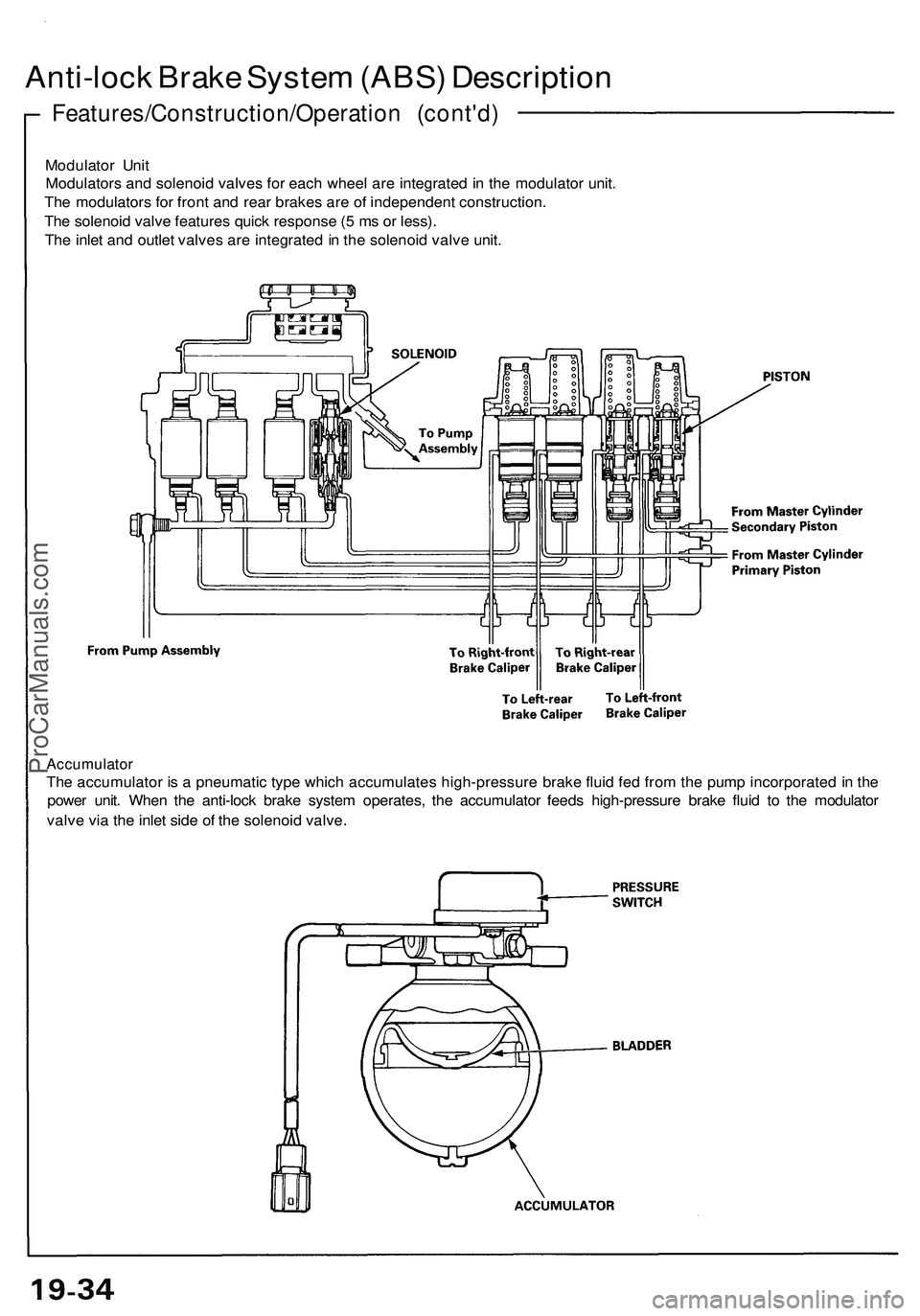
Accumulator
The accumulator is a pneumatic type which accumulates high-pressure brake fluid fed from the pump incorporated in the
power unit. When the anti-lock brake system operates, the accumulator feeds high-pressure brake fluid to the modulator
valve via the inlet side of the solenoid valve.
Modulator Unit
Modulators and solenoid valves for each wheel are integrated in the modulator unit.
The modulators for front and rear brakes are of independent construction.
The solenoid valve features quick response (5 ms or less).
The inlet and outlet valves are integrated in the solenoid valve unit.
Features/Construction/Operation (cont'd)
Anti-lock Brake System (ABS) DescriptionProCarManuals.com
Page 1363 of 1503
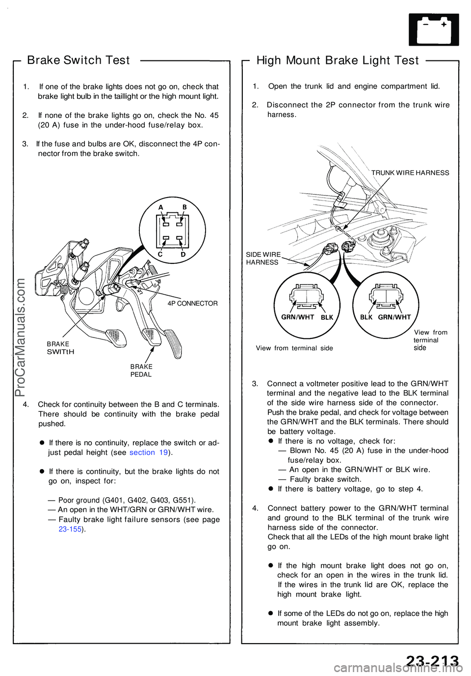
Brake Switc h Tes t
1. I f on e o f th e brak e light s doe s no t g o on , chec k tha t
brak e ligh t bul b in th e tailligh t o r th e hig h moun t light .
2. I f non e o f th e brak e light s g o on , chec k th e No . 4 5
(2 0 A ) fus e i n th e under-hoo d fuse/rela y box .
3 . I f th e fus e an d bulb s ar e OK , disconnec t th e 4 P con -
necto r fro m th e brak e switch .
4P CONNECTO R
BRAKESWITtH
BRAK EPEDAL
4. Chec k fo r continuit y betwee n th e B an d C terminals .
Ther e shoul d b e continuit y wit h th e brak e peda l
pushed .
I f ther e i s n o continuity , replac e th e switc h o r ad -
jus t peda l heigh t (se e sectio n 19 ).
I f ther e i s continuity , bu t th e brak e light s d o no t
g o on , inspec t for :
— Poo r groun d (G401 , G402 , G403 , G551) .
— An ope n in th e WHT/GR N o r GRN/WH T wire .
— Fault y brak e ligh t failur e sensor s (se e pag e
23-155 ).
Hig h Moun t Brak e Ligh t Tes t
1. Ope n th e trun k li d an d engin e compartmen t lid .
2 . Disconnec t th e 2 P connecto r fro m th e trun k wir e
harness .
TRUNK WIR E HARNES S
SID E WIR E
HARNES S
View fro m termina l sid e Vie
w fro m
termina lside
3. Connec t a voltmete r positiv e lea d t o th e GRN/WH T
termina l an d th e negativ e lea d t o th e BL K termina l
o f th e sid e wir e harnes s sid e o f th e connector .
Pus h th e brak e pedal , an d chec k fo r voltag e betwee n
th e GRN/WH T an d th e BL K terminals . Ther e shoul d
b e batter y voltage .
I f ther e i s n o voltage , chec k for :
— Blow n No . 4 5 (2 0 A ) fus e i n th e under-hoo d
fuse/rela y box .
— A n ope n i n th e GRN/WH T o r BL K wire .
— Fault y brak e switch .
I f ther e i s batter y voltage , g o t o ste p 4 .
4 . Connec t batter y powe r t o th e GRN/WH T termina l
an d groun d t o th e BL K termina l o f th e trun k wir e
harnes s sid e o f th e connector .
Chec k tha t al l th e LED s o f th e hig h moun t brak e ligh t
go on .
If th e hig h moun t brak e ligh t doe s no t g o on ,
chec k fo r a n ope n i n th e wire s i n th e trun k lid .
I f th e wire s i n th e trun k li d ar e OK , replac e th e
hig h moun t brak e light .
I f som e o f th e LED s d o no t g o on , replac e th e hig h
moun t brak e ligh t assembly .
ProCarManuals.com
Page 1450 of 1503
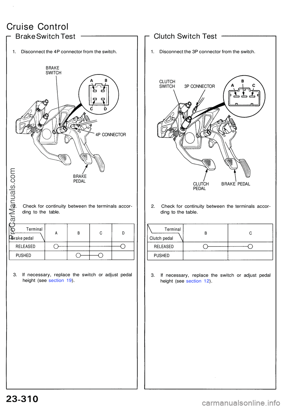
Cruise Contro l
Brake Switc h Tes t
1. Disconnec t th e 4 P connecto r fro m th e switch .
BRAKESWITC H
4P CONNECTO R
BRAKE
PEDA L
2. Chec k fo r continuit y betwee n th e terminal s accor -
din g t o th e table .
3 . I f necessary , replac e th e switc h o r adjus t peda l
heigh t (se e sectio n 19 ).
Clutc h Switc h Tes t
1. Disconnec t th e 3 P connecto r fro m th e switch .
CLUTC H
SWITC H 3 P CONNECTO R
CLUTC H BRAK E PEDA L
PEDA L
2. Chec k fo r continuit y betwee n th e terminal s accor -
ding t o th e table .
3. I f necessary , replac e th e switc h o r adjus t peda l
heigh t (se e sectio n 12 ).
Termina l
Brak e peda l
RELEASE D
PUSHED
ABCDTermina l
Clutch peda l
RELEASE D
PUSHED
BC
ProCarManuals.com