wheel bolt torque ACURA NSX 1997 Service Repair Manual
[x] Cancel search | Manufacturer: ACURA, Model Year: 1997, Model line: NSX, Model: ACURA NSX 1997Pages: 1503, PDF Size: 57.08 MB
Page 385 of 1503
Service Precautions
Handling of Special Nuts and Bolts
Handling of Tires
• The tires on NSX & NSX-T should not be rotated. The
front wheels are 16" in, diameter and the rear wheels
are 17" in, so they cannot be rotated front-to-rear.
The original-equipment tires on NSX & NSX-T have a
unidirectional tread pattern, so they cannot be rotat-
ed side-to-side.
• The folding spare tire cannot be repaired or removed
from the rim.
Engine Steam-cleaning
(NSX-T only)
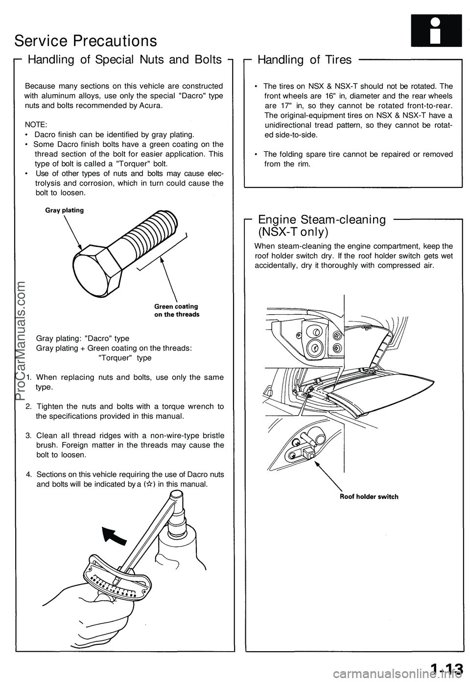
When steam-cleaning the engine compartment, keep the
roof holder switch dry. If the roof holder switch gets wet
accidentally, dry it thoroughly with compressed air.
Because many sections on this vehicle are constructed
with aluminum alloys, use only the special "Dacro" type
nuts and bolts recommended by Acura.
NOTE:
• Dacro finish can be identified by gray plating.
• Some Dacro finish bolts have a green coating on the
thread section of the bolt for easier application. This
type of bolt is called a "Torquer" bolt.
• Use of other types of nuts and bolts may cause elec-
trolysis and corrosion, which in turn could cause the
bolt to loosen.
Gray plating: "Dacro" type
Gray plating + Green coating on the threads:
"Torquer" type
1. When replacing nuts and bolts, use only the same
type.
2. Tighten the nuts and bolts with a torque wrench to
the specifications provided in this manual.
3. Clean all thread ridges with a non-wire-type bristle
brush. Foreign matter in the threads may cause the
bolt to loosen.
4. Sections on this vehicle requiring the use of Dacro nuts
and bolts will be indicated by a in this manual.ProCarManuals.com
Page 713 of 1503
Description
The automatic transmission is a combination of a 3-element torque converter and a triple-shaft electronically controlled
automatic transmission which provides 4 speeds forward and 1 speed reverse. The entire unit is positioned in line with the
engine.
Torque Converter, Gears, and Clutches
The torque converter consists of a pump, turbine, and stator, assembled in a single unit.
They are connected to the engine crankshaft so they turn together as a unit as the engine turns.
Around the outside of the torque converter is a ring gear which meshes with the starter pinion when the engine is being
started. The entire torque converter assembly serves as a flywheel while transmitting power to the transmission main-
shaft. The transmission has three parallel shafts: the mainshaft, the countershaft, and the secondary shaft. The mainshaft
is in line with the engine crankshaft.
The mainshaft includes the 1st and 4th clutches, and gears for 3rd, 4th, reverse, and 1st (3rd gear is integral with the main-
shaft, while reverse gear is integral with 4th gear).
The countershaft includes the 1st-hold and 3rd clutches, and gears for 2nd, 3rd, 4th, reverse, 1st, and parking.
The secondary shaft includes the 2nd clutch and gears for 2nd and 3rd.
The 4th and reverse gears can be locked to the countershaft at its center, providing 4th gear or reverse, depending on
which way the selector is moved.
The gears on the mainshaft and secondary shaft are in constant mesh with those on the countershaft.
When certain combinations of gears in the transmission are engaged by clutches, power is transmitted from the mainshaft
to the countershaft to provide positions.
Electronic Control
The electronic control system consists of the Transmission Control Module (TCM), sensors, a linear solenoid, a shift switch,
and 4 solenoid valves. Shifting and lock-up are electronically controlled for comfortable driving under all conditions.
The TCM is located on the insulator center bulkhead, behind the driver's seat.
Hydraulic Control
The valve bodies include the main valve body, secondary valve body, servo body, regulator valve body, throttle valve
body, lock-up valve body, and the 2nd accumulator body.
They are bolted to the torque converter housing as an assembly.
The main valve body contains the manual valve, 1-2 shift valve, 2-3 shift valve, 3-4 shift valve, relief valve, one-way relief
valve, and oil pump gears.
The secondary valve body contains the 3-2 kick-down valve, clutch pressure control (CPC) valve, 2nd orifice control valve, 3rd
orifice control valve, modulator valve, 4th exhaust valve, servo control valve, 2nd exhaust valve, and 4-3 kick-down valve.
The servo body contains the accumulator pistons and servo valve. The throttle valve body includes the throttle valve B
which is bolted to the servo body.
The regulator valve body contains the pressure regulator valve, lock-up control valve, and cooler relief valve. Fluid from
the regulator passes through the manual valve to the various control valves.
The lock-up valve body contains the lock-up timing B valve and lock-up shift valve. The 2nd accumulator body contains
the accumulator pistons and limited slip differential relief valve.
The torque converter check valve is located in the torque converter housing, under the main valve body.
The 1st, 1st-hold, 3rd, and 4th clutches receive fluid from their respective feed pipes and the 2nd clutch receives fluid from
the internal hydraulic circuit.
Shift Control Mechanism
Input from various sensors located throughout the vehicle determines which shift control solenoid valve the TCM will acti-
vate. Activating a shift control solenoid valve changes modulator pressure, causing a shift valve to move. This pressurizes
a line to one of the clutches, engaging that clutch and its corresponding gear.
Lock-up Mechanism
In position and position in 2nd, 3rd, and 4th, pressurized fluid is drained from the back of the torque converter
through a fluid passage, causing the lock-up piston to be held against the torque converter cover. As this takes place, the
mainshaft rotates at the same speed as the engine crankshaft. Together with hydraulic control, the TCM optimizes the tim-
ing of the lock-up mechanism.
The lock-up valves control the range of lock-up according to lock-up control solenoid valves A and B, and throttle valve B.
When lock-up control solenoid valves A and B activate, modulator pressure changes. The lock-up control solenoid valves
A and B are mounted on the torque converter housing, and are controlled by the TCM.
(cont'd)ProCarManuals.com
Page 979 of 1503
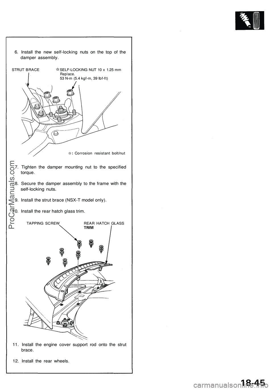
6. Install the new self-locking nuts on the top of the
damper assembly.
STRUT BRACE SELF-LOCKING NUT 10 x 1.25 mm
Replace.
53 N-m (5.4 kgf-m, 39 Ibf-ft)
Corrosion resistant bolt/nut
7. Tighten the damper mounting nut to the specified
torque.
8. Secure the damper assembly to the frame with the
self-locking nuts.
9. Install the strut brace (NSX-T model only).
10. Install the rear hatch glass trim.
TAPPING SCREW REAR HATCH GLASS
11. Install the engine cover support rod onto the strut
brace.
12. Install the rear wheels.ProCarManuals.com
Page 986 of 1503
Inspection/Replacement (cont'd )
Front Brak e Pad s
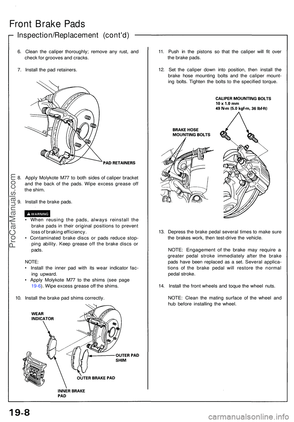
6. Clea n th e calipe r thoroughly ; remov e an y rust , an d
chec k fo r groove s an d cracks .
7 . Instal l th e pa d retainers . 11
. Pus h i n th e piston s s o tha t th e calipe r wil l fi t ove r
th e brak e pads .
12 . Se t th e calipe r dow n int o position , the n instal l th e
brak e hos e mountin g bolt s an d th e calipe r mount -
in g bolts . Tighte n th e bolt s t o th e specifie d torque .
8 . Appl y Molykot e M7 7 t o bot h side s o f calipe r bracke t
an d th e bac k o f th e pads . Wip e exces s greas e of f
the shim .
9. Instal l th e brak e pads .
• Whe n reusin g th e pads , alway s reinstal l th e
brak e pad s i n thei r origina l position s t o preven t
los s o f brakin g efficiency .
• Contaminate d brak e disc s o r pad s reduc e stop -
pin g ability . Kee p greas e of f th e brak e disc s o r
pads .
NOTE :
• Instal l th e inne r pa d wit h it s wea r indicator fac-
in g upward .
• Appl y Molykot e M7 7 t o th e shim s (se e pag e
19-6 ). Wip e exces s greas e of f th e shims .
10 . Instal l th e brak e pa d shim s correctly . 13
. Depres s th e brak e peda l severa l time s t o mak e sur e
th e brake s work , the n test-driv e th e vehicle .
NOTE: Engagemen t o f th e brak e ma y requir e a
greate r peda l strok e immediatel y afte r th e brak e
pad s hav e bee n replace d a s a set . Severa l applica -
tion s of the brak e peda l wil l restor e th e norma l
peda l stroke .
14 . Instal l th e fron t wheel s an d toqu e th e whee l nuts .
NOTE : Clea n th e matin g surfac e o f th e whee l an d
hu b befor e installin g th e wheel .
ProCarManuals.com
Page 999 of 1503
Inspection/Replacement (cont'd)
Rear Brake Pads
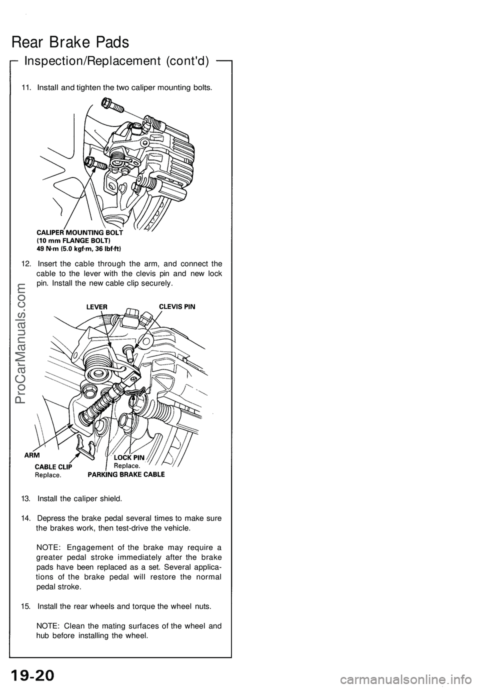
11. Install and tighten the two caliper mounting bolts.
12. Insert the cable through the arm, and connect the
cable to the lever with the clevis pin and new lock
pin. Install the new cable clip securely.
13. Install the caliper shield.
14. Depress the brake pedal several times to make sure
the brakes work, then test-drive the vehicle.
NOTE: Engagement of the brake may require a
greater pedal stroke immediately after the brake
pads have been replaced as a set. Several applica-
tions of the brake pedal will restore the normal
pedal stroke.
15. Install the rear wheels and torque the wheel nuts.
NOTE: Clean the mating surfaces of the wheel and
hub before installing the wheel.ProCarManuals.com