change time ACURA NSX 1997 Service Repair Manual
[x] Cancel search | Manufacturer: ACURA, Model Year: 1997, Model line: NSX, Model: ACURA NSX 1997Pages: 1503, PDF Size: 57.08 MB
Page 570 of 1503

Troubleshooting
Troubleshooting Procedures (cont'd)
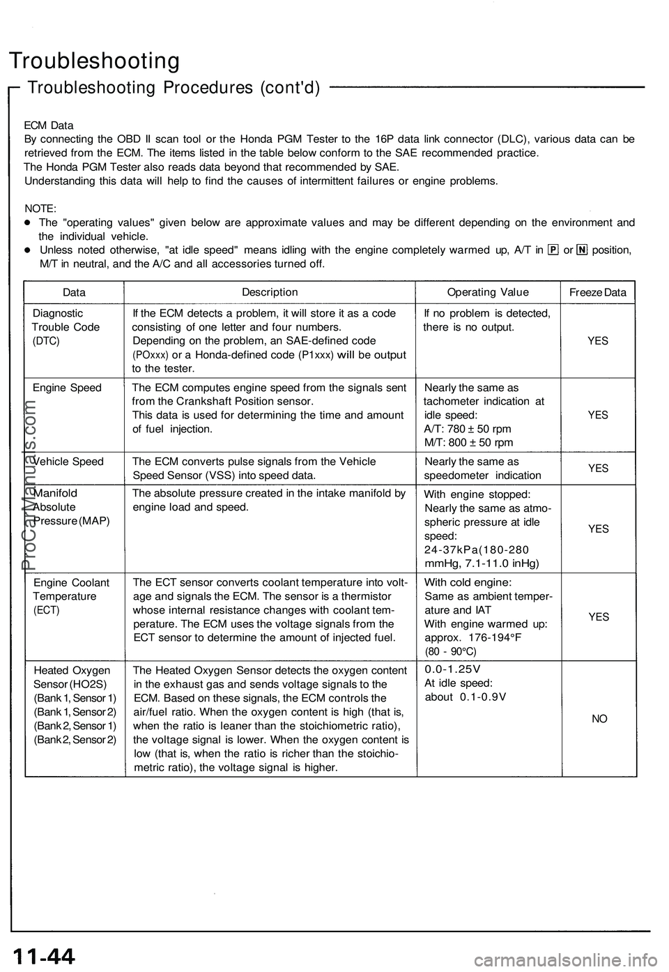
ECM Data
By connecting the OBD II scan tool or the Honda PGM Tester to the 16P data link connector (DLC), various data can be
retrieved from the ECM. The items listed in the table below conform to the SAE recommended practice.
The Honda PGM Tester also reads data beyond that recommended by SAE.
Understanding this data will help to find the causes of intermittent failures or engine problems.
NOTE:
The "operating values" given below are approximate values and may be different depending on the environment and
the individual vehicle.
Unless noted otherwise, "at idle speed" means idling with the engine completely warmed up, A/T in or position,
M/T in neutral, and the A/C and all accessories turned off.
Data
Description
Operating Value
Freeze Data
Diagnostic
Trouble Code
(DTC)
If the ECM detects a problem, it will store it as a code
consisting of one letter and four numbers.
Depending on the problem, an SAE-defined code
(POxxx)
or a
Honda-defined code
(P1xxx)
will
be
output
to the tester.
If no problem is detected,
there is no output.
YES
Engine Speed
The ECM computes engine speed from the signals sent
from the Crankshaft Position sensor.
This data is used for determining the time and amount
of fuel injection.
Nearly the same as
tachometer indication at
idle speed:
A/T:
780 ± 50 rpm
M/T:
800 ± 50 rpm
YES
Vehicle Speed
The ECM converts pulse signals from the Vehicle
Speed Sensor (VSS) into speed data.
Nearly the same as
speedometer indication
YES
Manifold
Absolute
Pressure (MAP)
The absolute pressure created in the intake manifold by
engine load and speed.
With engine stopped:
Nearly the same as atmo-
spheric pressure at idle
speed:
24-37kPa(180-280
mmHg, 7.1-11.0 inHg)
YES
Engine Coolant
Temperature
(ECT)
The ECT sensor converts coolant temperature into volt-
age and signals the ECM. The sensor is a thermistor
whose internal resistance changes with coolant tem-
perature. The ECM uses the voltage signals from the
ECT sensor to determine the amount of injected fuel.
With cold engine:
Same as ambient temper-
ature and IAT
With engine warmed up:
approx. 176-194°F
(80 - 90°C)
YES
Heated Oxygen
Sensor (HO2S)
(Bank 1, Sensor 1)
(Bank 1, Sensor 2)
(Bank 2, Sensor 1)
(Bank 2, Sensor 2)
The Heated Oxygen Sensor detects the oxygen content
in the exhaust gas and sends voltage signals to the
ECM. Based on these signals, the ECM controls the
air/fuel ratio. When the oxygen content is high (that is,
when the ratio is leaner than the stoichiometric ratio),
the voltage signal is lower. When the oxygen content is
low (that is, when the ratio is richer than the stoichio-
metric ratio), the voltage signal is higher.
0.0-1.25V
At idle speed:
about 0.1-0.9V
NOProCarManuals.com
Page 903 of 1503

System Description
Function and Operation (cont'd)
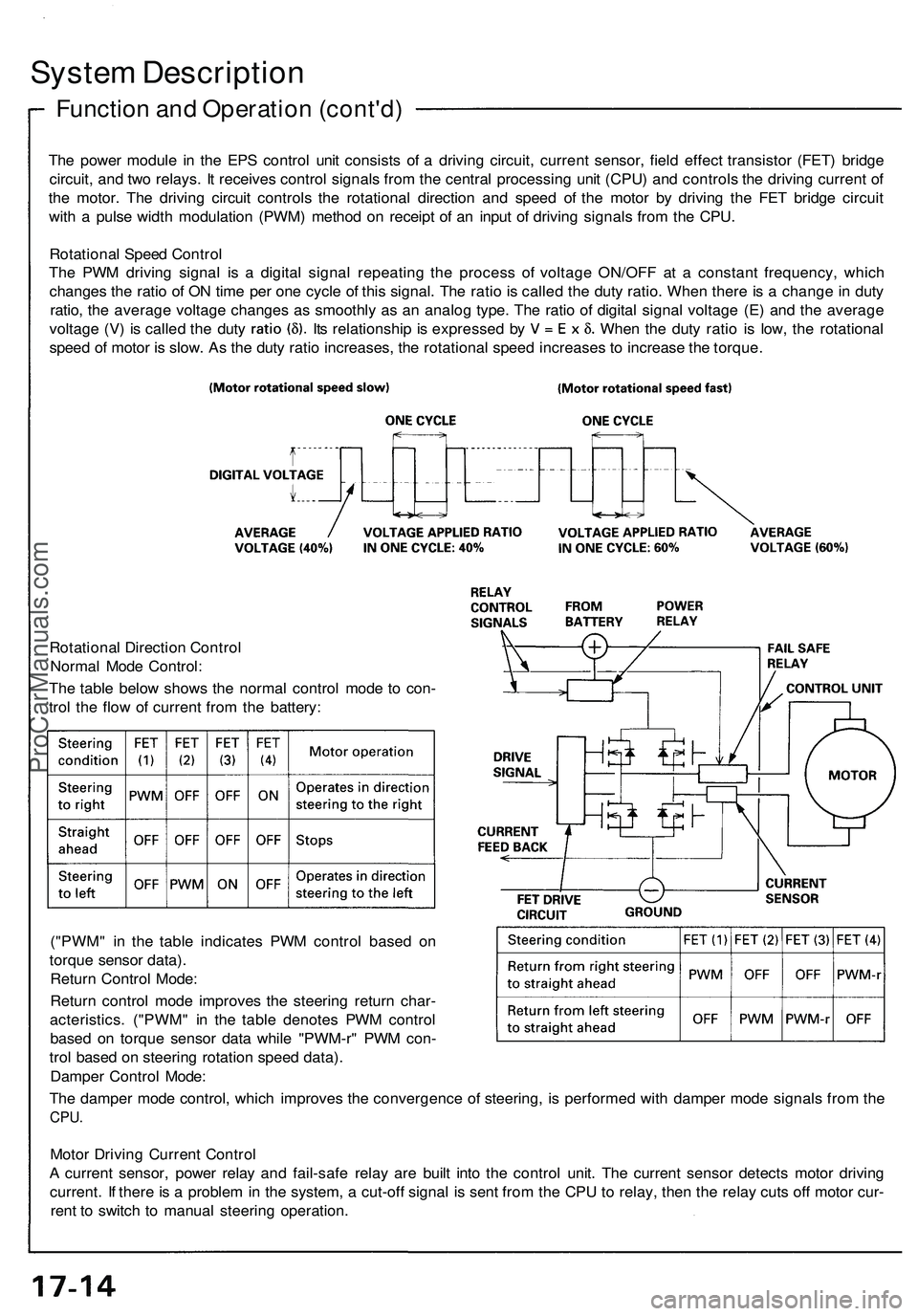
The power module in the EPS control unit consists of a driving circuit, current sensor, field effect transistor (FET) bridge
circuit, and two relays. It receives control signals from the central processing unit (CPU) and controls the driving current of
the motor. The driving circuit controls the rotational direction and speed of the motor by driving the FET bridge circuit
with a pulse width modulation (PWM) method on receipt of an input of driving signals from the CPU.
Rotational Speed Control
The PWM driving signal is a digital signal repeating the process of voltage ON/OFF at a constant frequency, which
changes the ratio of ON time per one cycle of this signal. The ratio is called the duty ratio. When there is a change in duty
ratio, the average voltage changes as smoothly as an analog type. The ratio of digital signal voltage (E) and the average
voltage (V) is called the duty Its relationship is expressed by When the duty ratio is low, the rotational
speed of motor is slow. As the duty ratio increases, the rotational speed increases to increase the torque.
Rotational Direction Control
Normal Mode Control:
The table below shows the normal control mode to con-
trol the flow of current from the battery:
("PWM" in the table indicates PWM control based on
torque sensor data).
Return Control Mode:
Return control mode improves the steering return char-
acteristics. ("PWM" in the table denotes PWM control
based on torque sensor data while "PWM-r" PWM con-
trol based on steering rotation speed data).
Damper Control Mode:
The damper mode control, which improves the convergence of steering, is performed with damper mode signals from the
CPU.
Motor Driving Current Control
A current sensor, power relay and fail-safe relay are built into the control unit. The current sensor detects motor driving
current. If there is a problem in the system, a cut-off signal is sent from the CPU to relay, then the relay cuts off motor cur-
rent to switch to manual steering operation.ProCarManuals.com
Page 994 of 1503

Tests
Brake Booster
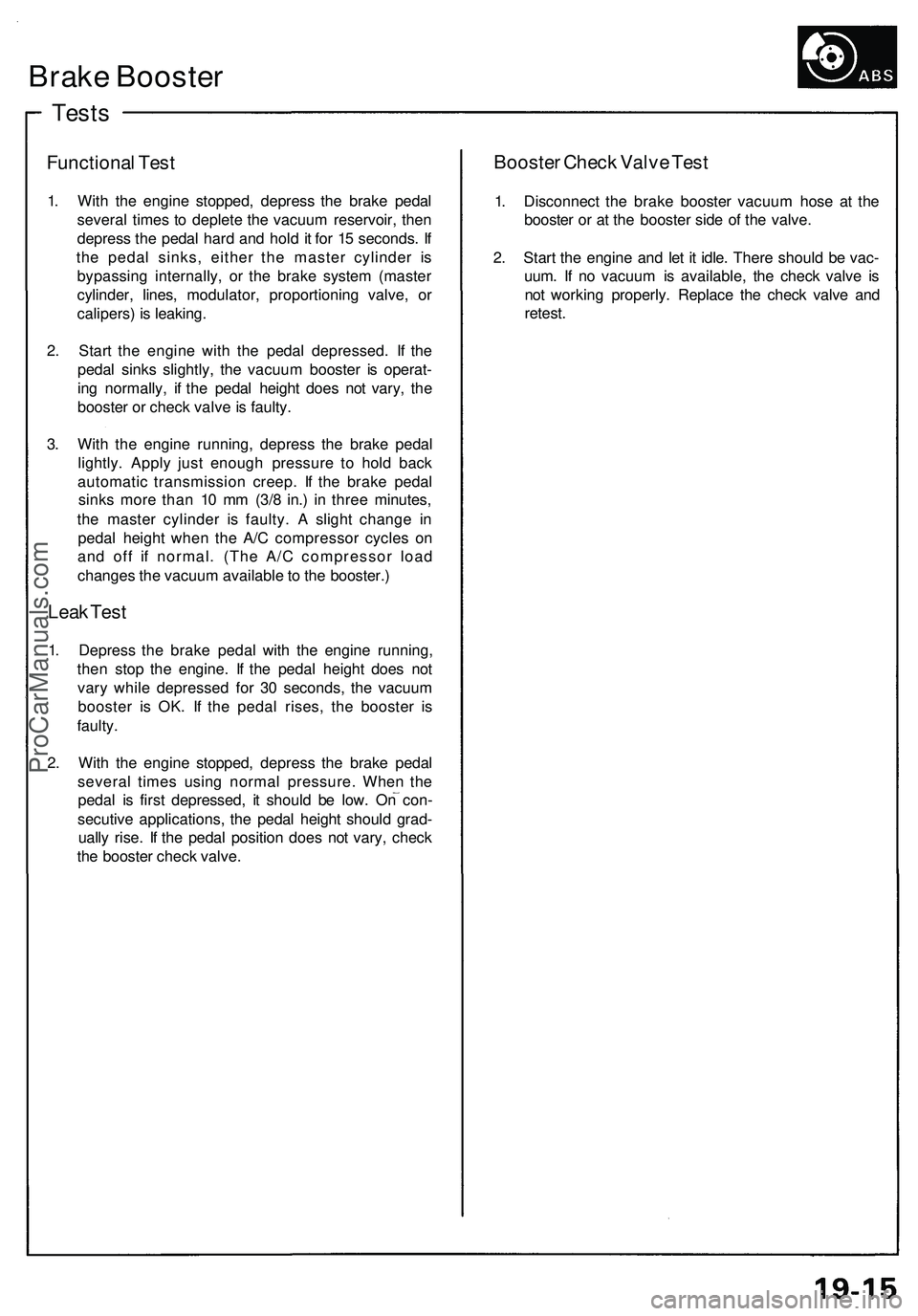
Functional Test
1. With the engine stopped, depress the brake pedal
several times to deplete the vacuum reservoir, then
depress the pedal hard and hold it for 15 seconds. If
the pedal sinks, either the master cylinder is
bypassing internally, or the brake system (master
cylinder, lines, modulator, proportioning valve, or
calipers) is leaking.
2. Start the engine with the pedal depressed. If the
pedal sinks slightly, the vacuum booster is operat-
ing normally, if the pedal height does not vary, the
booster or check valve is faulty.
3. With the engine running, depress the brake pedal
lightly. Apply just enough pressure to hold back
automatic transmission creep. If the brake pedal
sinks more than 10 mm (3/8 in.) in three minutes,
the master cylinder is faulty. A slight change in
pedal height when the A/C compressor cycles on
and off if normal. (The A/C compressor load
changes the vacuum available to the booster.)
Leak Test
1. Depress the brake pedal with the engine running,
then stop the engine. If the pedal height does not
vary while depressed for 30 seconds, the vacuum
booster is OK. If the pedal rises, the booster is
faulty.
2. With the engine stopped, depress the brake pedal
several times using normal pressure. When the
pedal is first depressed, it should be low. On con-
secutive applications, the pedal height should grad-
ually rise. If the pedal position does not vary, check
the booster check valve.
Booster Check Valve Test
1. Disconnect the brake booster vacuum hose at the
booster or at the booster side of the valve.
2. Start the engine and let it idle. There should be vac-
uum. If no vacuum is available, the check valve is
not working properly. Replace the check valve and
retest.ProCarManuals.com