window ACURA NSX 1997 Service Repair Manual
[x] Cancel search | Manufacturer: ACURA, Model Year: 1997, Model line: NSX, Model: ACURA NSX 1997Pages: 1503, PDF Size: 57.08 MB
Page 60 of 1503
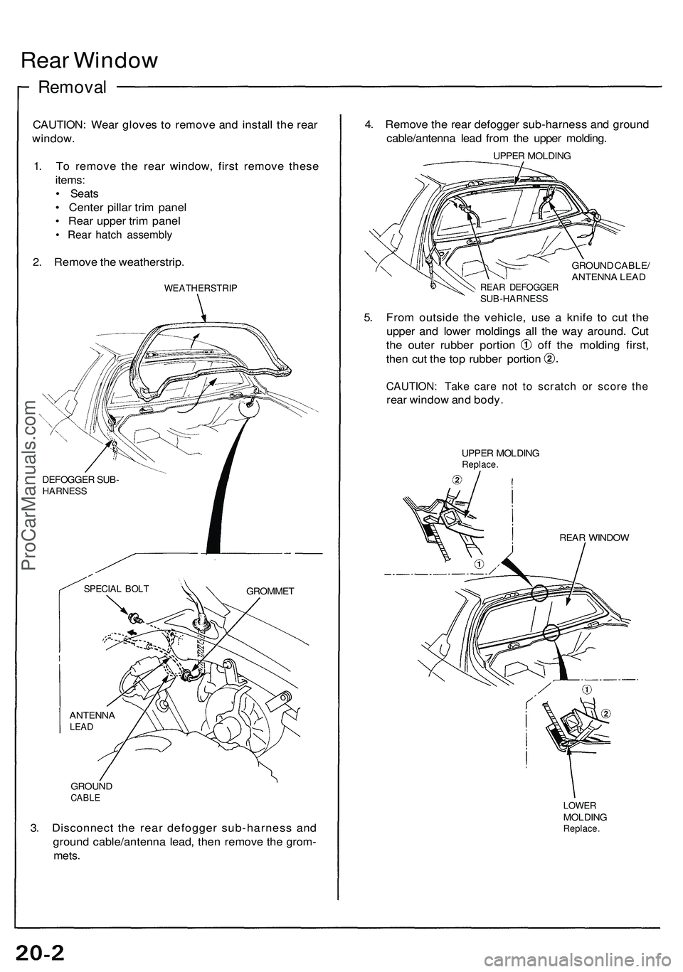
Rear Windo w
Remova l
CAUTION : Wea r glove s t o remov e an d instal l th e rea r
window .
1 . T o remov e th e rea r window , firs t remov e thes e
items :
• Seat s
• Cente r pilla r tri m pane l
• Rea r uppe r tri m pane l
• Rea r hatc h assembl y
2. Remov e th e weatherstrip .
GROUNDCABLE
3. Disconnec t th e rea r defogge r sub-harnes s an d
groun d cable/antenn a lead , the n remov e th e grom -
mets.
4. Remov e th e rea r defogge r sub-harnes s an d groun d
cable/antenn a lea d fro m th e uppe r molding .
UPPER MOLDIN G
GROUN D CABLE /
ANTENN A LEA D
REA R DEFOGGE RSUB-HARNES S
5. Fro m outsid e th e vehicle , us e a knif e t o cu t th e
uppe r an d lowe r molding s al l th e wa y around . Cu t
the oute r rubbe r portio n of f th e moldin g first ,
then cu t th e to p rubbe r portio n
CAUTION : Tak e car e no t t o scratc h o r scor e th e
rea r windo w an d body .
UPPE R MOLDIN GReplace.
REAR WINDO W
LOWERMOLDIN GReplace .
ANTENN ALEAD
SPECIA L BOL TGROMME T
DEFOGGE
R SUB -
HARNES S
WEATHERSTRI P
ProCarManuals.com
Page 61 of 1503
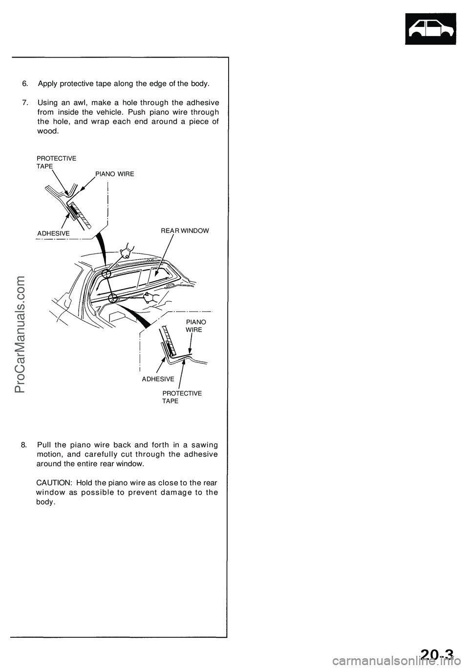
6. Apply protective tape along the edge of the body.
7. Using an awl, make a hole through the adhesive
from inside the vehicle. Push piano wire through
the hole, and wrap each end around a piece of
wood.
PROTECTIVE
TAPE
PIANO WIRE
ADHESIVE
REAR WINDOW
ADHESIVE
PROTECTIVE
TAPE
8. Pull the piano wire back and forth in a sawing
motion, and carefully cut through the adhesive
around the entire rear window.
CAUTION: Hold the piano wire as close to the rear
window as possible to prevent damage to the
body.
PIANO
WIREProCarManuals.com
Page 62 of 1503
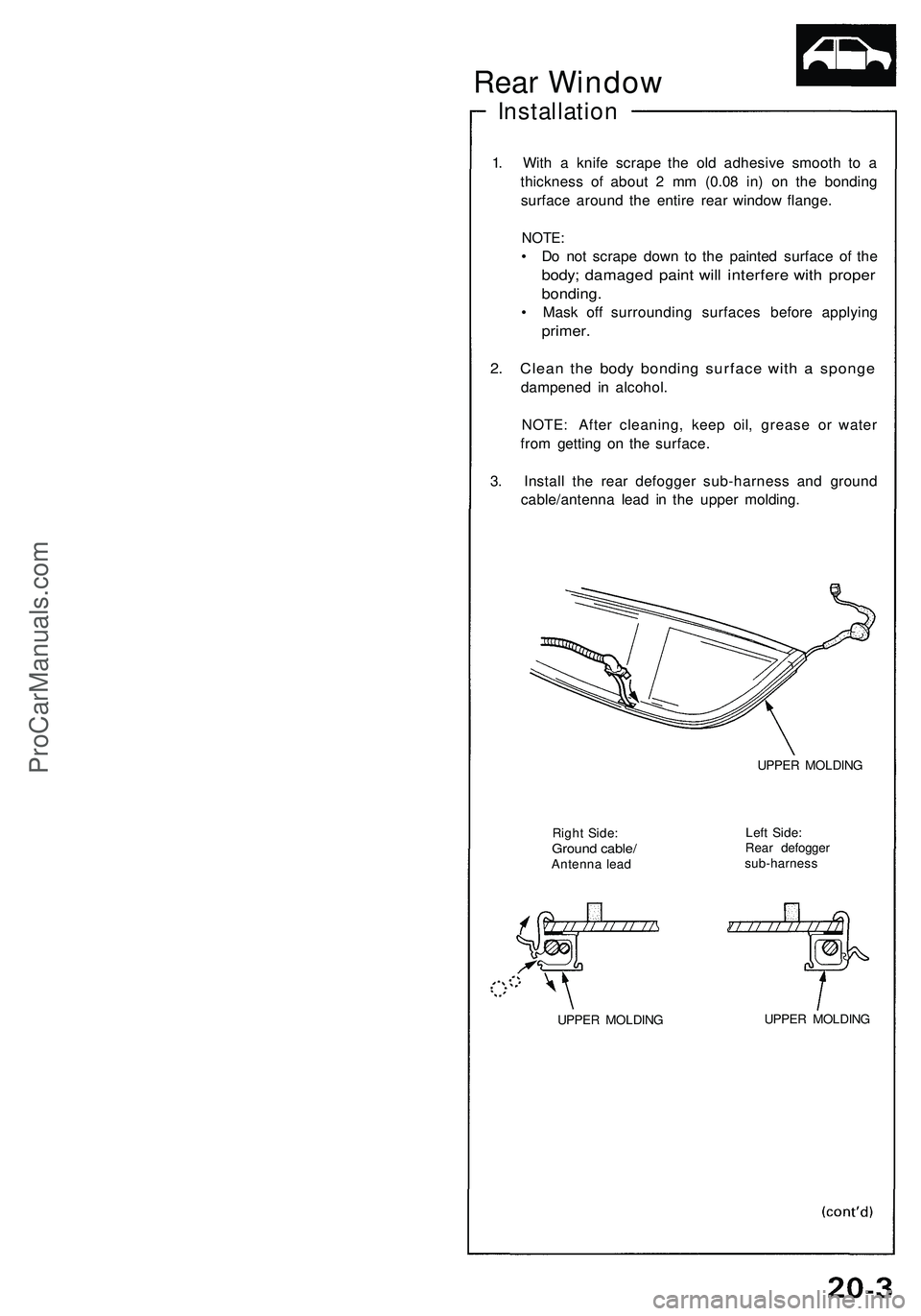
Installation
1. Wit h a knif e scrap e th e ol d adhesiv e smoot h t o a
thicknes s o f abou t 2 m m (0.0 8 in ) o n th e bondin g
surfac e aroun d th e entir e rea r windo w flange .
NOTE:
• D o no t scrap e dow n t o th e painte d surfac e o f th e
body ; damage d pain t wil l interfer e wit h prope r
bonding .
• Mas k of f surroundin g surface s befor e applyin g
primer.
2. Clea n th e bod y bondin g surfac e wit h a spong e
dampene d i n alcohol .
NOTE : Afte r cleaning , kee p oil , greas e o r wate r
fro m gettin g o n th e surface .
3 . Instal l th e rea r defogge r sub-harnes s an d groun d
cable/antenn a lea d i n th e uppe r molding .
Right Side :Groun d cable /Antenn a lea d UPPE
R MOLDIN G
Lef t Side :
Rea r defogge rsub-harnes s
UPPER MOLDIN G UPPE
R MOLDIN G
Rear Window
ProCarManuals.com
Page 63 of 1503
Rear Windo w
Installatio n (cont'd )
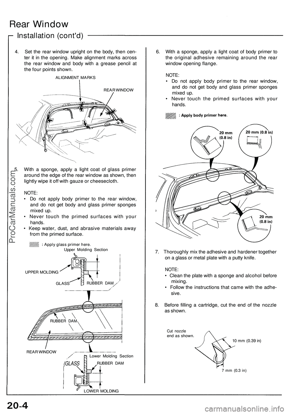
4. Se t th e rea r windo w uprigh t o n th e body , the n cen -
te r i t i n th e opening . Mak e alignmen t mark s acros s
th e rea r windo w an d bod y wit h a greas e penci l a t
th e fou r point s shown .
ALIGNMEN T MARK S
REAR WINDO W
5. Wit h a sponge , apply a ligh t coa t of glas s prime r
aroun d th e edg e o f th e rea r windo w a s shown , the n
lightl y wip e it of f wit h gauz e o r cheesecloth .
NOTE:
• D o no t appl y bod y prime r t o th e rea r window ,
an d d o no t ge t bod y an d glas s prime r sponge s
mixe d up .
• Neve r touc h th e prime d surface s wit h you r
hands .
• Kee p water , dust , an d abrasiv e material s awa y
fro m th e prime d surface .
REAR WINDO W
(GLASS
Lower Moldin g Sectio n
RUBBER DA M
LOWE R MOLDIN G
6. Wit h a sponge , appl y a ligh t coa t o f bod y prime r t o
th e origina l adhesiv e remainin g aroun d th e rea r
windo w openin g flange .
NOTE:
• D o no t appl y bod y prime r t o th e rea r window ,
an d d o no t ge t bod y an d glas s prime r sponge s
mixe d up .
• Neve r touc h th e prime d surface s wit h you r
hands .
7. Thoroughl y mi x th e adhesiv e an d hardene r togethe r
o n a glas s o r meta l plat e wit h a putt y knife .
NOTE :
• Clean the plat e wit h a spong e an d alcoho l befor e
mixing .
• Follo w th e instruction s tha t cam e wit h th e adhe -
sive.
8. Befor e fillin g a cartridge , cu t th e en d o f th e nozzl e
a s shown .
Cut nozzl eend a s shown .10 m m (0.3 9 in)
7 m m (0. 3 in)
UPPE R MOLDIN G
GLASSRUBBE R DA M
RUBBE R DA M
Appl y glas s prime r here .
Uppe r Moldin g Sectio n
ProCarManuals.com
Page 64 of 1503
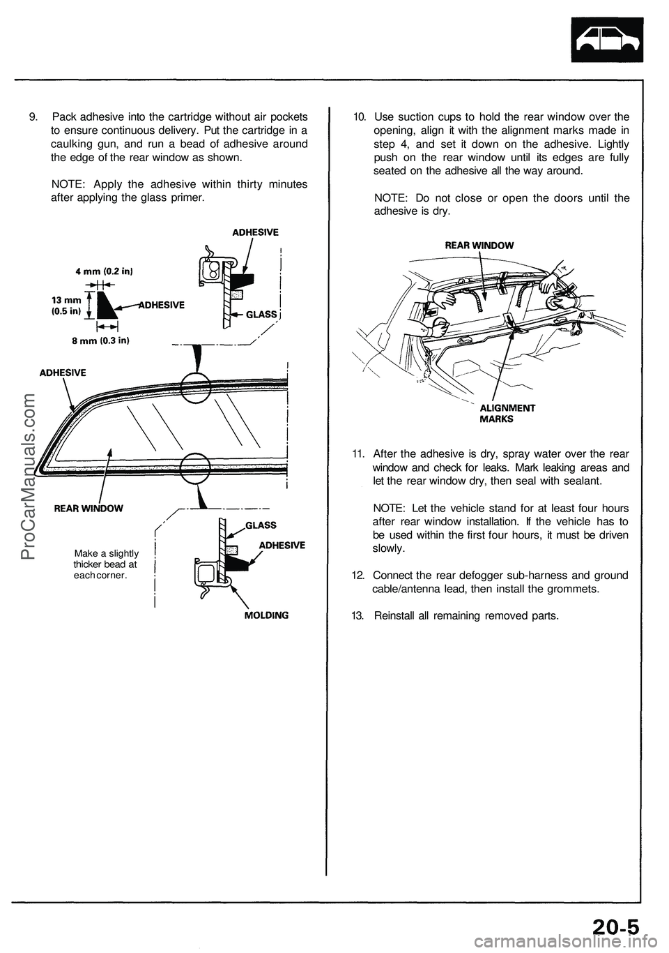
9. Pack adhesive into the cartridge without air pockets
to ensure continuous delivery. Put the cartridge in a
caulking gun, and run a bead of adhesive around
the edge of the rear window as shown.
NOTE: Apply the adhesive within thirty minutes
after applying the glass primer.
Make a slightly
thicker bead at
each corner.
10. Use suction cups to hold the rear window over the
opening, align it with the alignment marks made in
step 4, and set it down on the adhesive. Lightly
push on the rear window until its edges are fully
seated on the adhesive all the way around.
NOTE: Do not close or open the doors until the
adhesive is dry.
11. After the adhesive is dry, spray water over the rear
window and check for leaks. Mark leaking areas and
let the rear window dry, then seal with sealant.
NOTE: Let the vehicle stand for at least four hours
after rear window installation. If the vehicle has to
be used within the first four hours, it must be driven
slowly.
12. Connect the rear defogger sub-harness and ground
cable/antenna lead, then install the grommets.
13. Reinstall all remaining removed parts.ProCarManuals.com
Page 167 of 1503
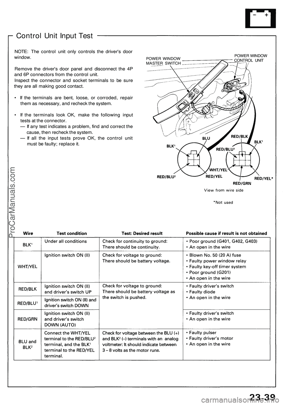
Control Unit Input Test
NOTE: The control unit only controls the driver's door
window.
Remove the driver's door panel and disconnect the 4P
and 6P connectors from the control unit.
Inspect the connector and socket terminals to be sure
they are all making good contact.
• If the terminals are bent, loose, or corroded, repair
them as necessary, and recheck the system.
• If the terminals look OK, make the following input
tests at the connector.
— If any test indicates a problem, find and correct the
cause, then recheck the system.
— If all the input tests prove OK, the control unit
must be faulty; replace it.
POWER WINDOW
MASTER SWITCH
POWER WINDOW
CONTROL UNITProCarManuals.com
Page 193 of 1503
Radiator
Engine Coolant Refilling and Bleeding
CAUTION: When pouring engine coolant, be sure to
shut the relay box lid and not let coolant spill on the
electrical parts or the paint. If any coolant spills, rinse it
off immediately.
NOTE:
• Perform this maintenance when the engine is cool.
• Before replacing the coolant, turn the ignition ON,
slowly turn the climate control temperature knob to
90° and turn off the ignition. This will allow the
coolant in the heater to drain out with the rest of the
system.
1. Open the hood, the rear window and the engine
cover.
2. Remove the cover protecting the water pipes and
shift cables on the underside of the car.
3. Before removing the expansion tank cap, first
loosen the cap to lower pressure.
CAUTION: Do not remove the expansion tank cap
when engine is hot. The coolant is under pressure
and may blow out and scald you. Open the cap
slowly when the engine is cool.
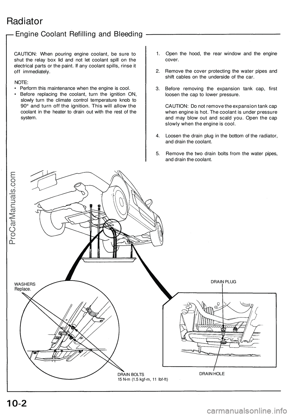
4. Loosen the drain plug in the bottom of the radiator,
and drain the coolant.
5. Remove the two drain bolts from the water pipes,
and drain the coolant.
DRAIN BOLTS
15 N-m (1.5 kgf-m, 11 Ibf-ft)
DRAIN HOLE
DRAIN PLUG
WASHERS
Replace.ProCarManuals.com
Page 521 of 1503
Engine Coolant Refilling and Bleeding
CAUTION: When pouring engine coolant, be sure to
shut the relay box lid and not let coolant spill on the
electrical parts or the paint. If any coolant spills, rinse it
off immediately.
NOTE:
• Perform this maintenance when the engine is cool.
• Before replacing the coolant, turn the ignition ON,
slowly turn the climate control temperature knob to
90° and turn off the ignition. This will allow the
coolant in the heater to drain out with the rest of the
system.
1. Open the hood, the rear window and the engine
cover.
2. Remove the cover protecting the water pipes and
shift cables on the underside of the car.
3. Before removing the expansion tank cap, first
loosen the cap to lower pressure.
CAUTION: Do not remove the expansion tank cap
when engine is hot. The coolant is under pressure
and may blow out and scald you. Open the cap
slowly when the engine is cool.
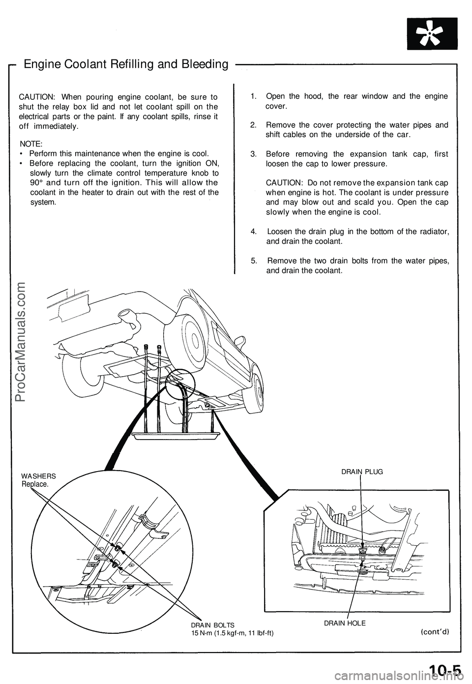
4. Loosen the drain plug in the bottom of the radiator,
and drain the coolant.
5. Remove the two drain bolts from the water pipes,
and drain the coolant.
WASHERS
Replace.
DRAIN BOLTS
15 N-m (1.5 kgf-m, 11 Ibf-ft)
DRAIN HOLE
DRAIN PLUGProCarManuals.com
Page 973 of 1503
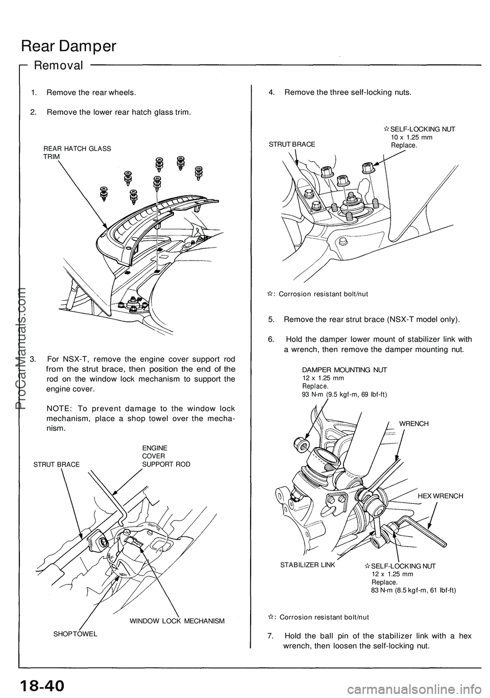
Rear Damper
Removal
1. Remove the rear wheels.
2. Remove the lower rear hatch glass trim.
REAR HATCH GLASS
TRIM
3. For NSX-T, remove the engine cover support rod
from the strut brace, then position the end of the
rod on the window lock mechanism to support the
engine cover.
NOTE: To prevent damage to the window lock
mechanism, place a shop towel over the mecha-
nism.
STRUT BRACE
ENGINE
COVER
SUPPORT ROD
WINDOW LOCK MECHANISM
SHOP TOWEL
4. Remove the three self-locking nuts.
STRUT BRACE
SELF-LOCKING NUT
10 x
1.25
mm
Replace.
Corrosion resistant bolt/nut
5. Remove the rear strut brace (NSX-T model only).
6. Hold the damper lower mount of stabilizer link with
a wrench, then remove the damper mounting nut.
DAMPER MOUNTING NUT
12 x
1.25
mm
Replace.
93 N-m (9.5 kgf-m, 69 Ibf-ft)
WRENCH
HEX WRENCH
STABILIZER LINK
SELF-LOCKING NUT
12 x
1.25
mm
Replace.
83 N-m (8.5 kgf-m, 61 Ibf-ft)
Corrosion resistant bolt/nut
7. Hold the ball pin of the stabilizer link with a hex
wrench, then loosen the self-locking nut.ProCarManuals.com
Page 1035 of 1503
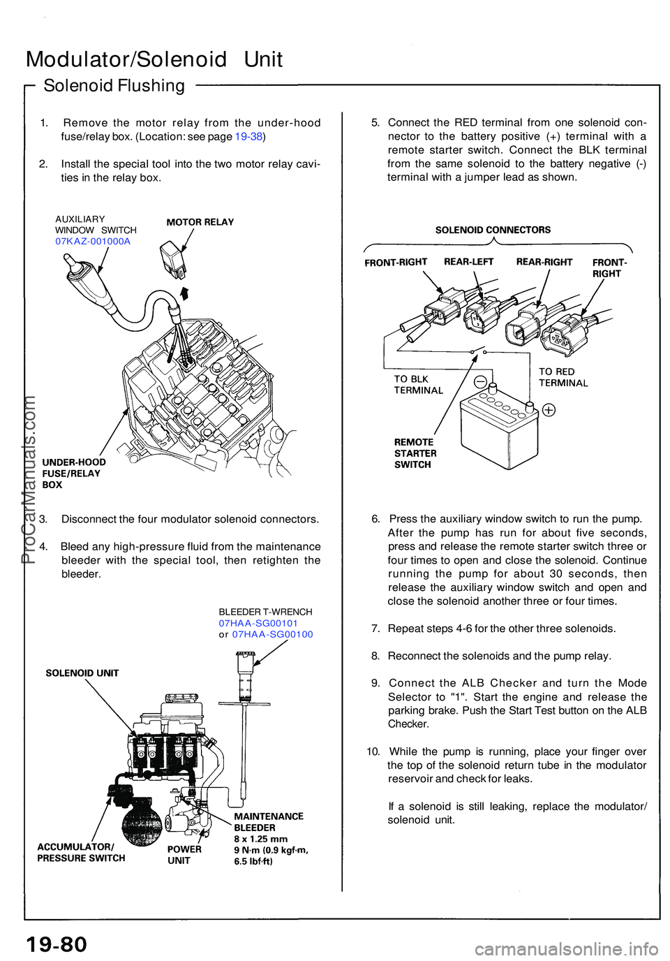
Solenoid Flushin g
Modulator/Solenoi d Uni t
1. Remov e th e moto r rela y fro m th e under-hoo d
fuse/rela y box . (Location : se e pag e 19-38 )
2 . Instal l th e specia l too l int o th e tw o moto r rela y cavi -
tie s in th e rela y box .
AUXILIAR YWINDOW SWITC H07KAZ-001000 A
5. Connec t th e RE D termina l fro m on e solenoi d con -
necto r t o th e batter y positiv e (+ ) termina l wit h a
remot e starte r switch . Connec t th e BL K termina l
fro m th e sam e solenoi d t o th e batter y negativ e (- )
termina l wit h a jumpe r lea d a s shown .
3 . Disconnec t th e fou r modulato r solenoi d connectors .
4 . Blee d an y high-pressur e flui d fro m th e maintenanc e
bleede r wit h th e specia l tool , the n retighte n th e
bleeder .
BLEEDE R T-WRENC H07HAA-SG0010 1or 07HAA-SG0010 0
6. Pres s th e auxiliar y windo w switc h t o ru n th e pump .
Afte r th e pum p ha s ru n fo r abou t fiv e seconds ,
pres s an d releas e th e remot e starte r switc h thre e o r
fou r time s t o ope n an d clos e th e solenoid . Continu e
runnin g th e pum p fo r abou t 3 0 seconds , the n
releas e th e auxiliar y windo w switc h an d ope n an d
clos e th e solenoi d anothe r thre e o r fou r times .
7 . Repea t step s 4- 6 fo r th e othe r thre e solenoids .
8 . Reconnec t th e solenoid s an d th e pum p relay .
9 . Connec t th e AL B Checke r an d tur n th e Mod e
Selecto r t o "1" . Star t th e engin e an d releas e th e
parkin g brake . Pus h th e Star t Tes t butto n o n th e AL B
Checker .
10. Whil e th e pum p i s running , plac e you r finge r ove r
th e to p o f th e solenoi d retur n tub e i n th e modulato r
reservoi r an d chec k fo r leaks .
I f a solenoi d i s stil l leaking , replac e th e modulator /
solenoi d unit .
ProCarManuals.com