clock ACURA NSX 1997 Service Repair Manual
[x] Cancel search | Manufacturer: ACURA, Model Year: 1997, Model line: NSX, Model: ACURA NSX 1997Pages: 1503, PDF Size: 57.08 MB
Page 130 of 1503
II. Engine Control Module (ECM) Reset Procedure
Either of the following actions, will reset the ECM.
• Using the OBD II scan tool or Honda PGM Tester to clear the ECM's memory.
NOTE: See the OBD II scan tool or Honda PGM Tester user's manuals for specific operating instructions.
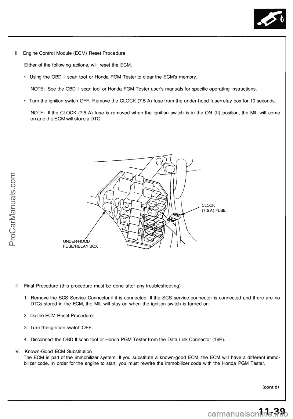
• Turn the ignition switch OFF. Remove the CLOCK (7.5 A) fuse from the under-hood fuse/relay box for 10 seconds.
NOTE: If the CLOCK (7.5 A) fuse is removed when the ignition switch is in the ON (II) position, the MIL will come
on and the ECM will store a DTC.
UNDER-HOOD
FUSE/RELAY BOX
CLOCK
(7.5 A) FUSE
III. Final Procedure (this procedure must be done after any troubleshooting)
1. Remove the SCS Service Connector if it is connected. If the SCS service connector is connected and there are no
DTCs stored in the ECM, the MIL will stay on when the ignition switch is turned on.
2. Do the ECM Reset Procedure.
3. Turn the ignition switch OFF.
4. Disconnect the OBD II scan tool or Honda PGM Tester from the Data Link Connector (16P).
IV. Known-Good ECM Substitution
The ECM is part of the immobilizer system. If you substitute a known-good ECM, the ECM will have a different immo-
bilizer code. In order for the engine to start, you must rewrite the immobilizer code with the Honda PGM Tester.ProCarManuals.com
Page 269 of 1503
Lighting Syste m
HID Bulb Removal
1. Mak e sur e yo u hav e th e anti-thef t cod e fo r th e radio ,
the n writ e dow n th e frequencie s fo r th e radio' s prese t
buttons .
2 . Tur n th e combinatio n ligh t switc h OFF .
3 . Disconnec t th e batter y negativ e cable , the n
disconnec t th e positiv e cable .
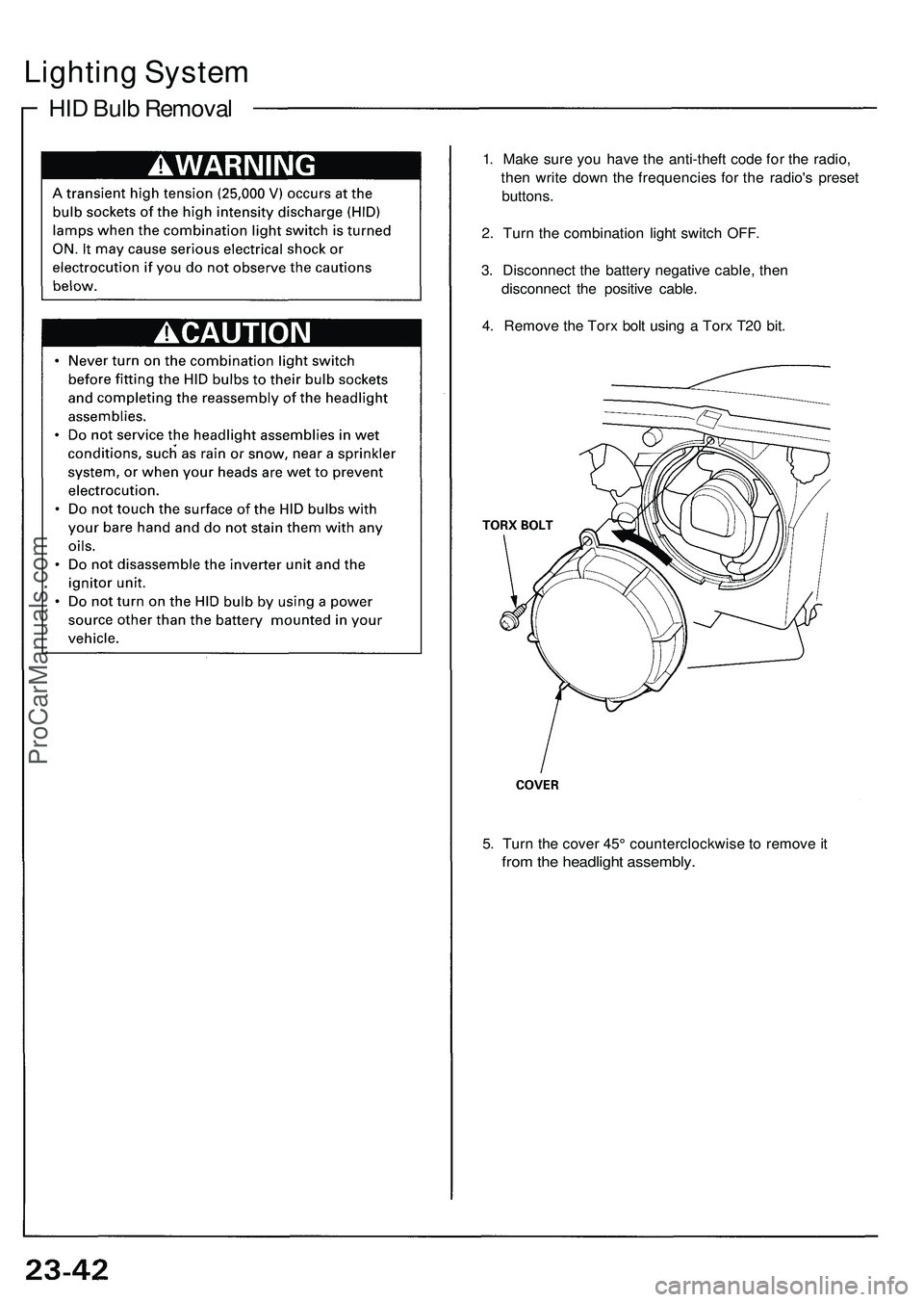
4 . Remov e th e Tor x bol t usin g a Tor x T2 0 bit .
5 . Tur n th e cove r 45 ° counterclockwis e to remov e it
fro m th e headligh t assembly .
ProCarManuals.com
Page 270 of 1503
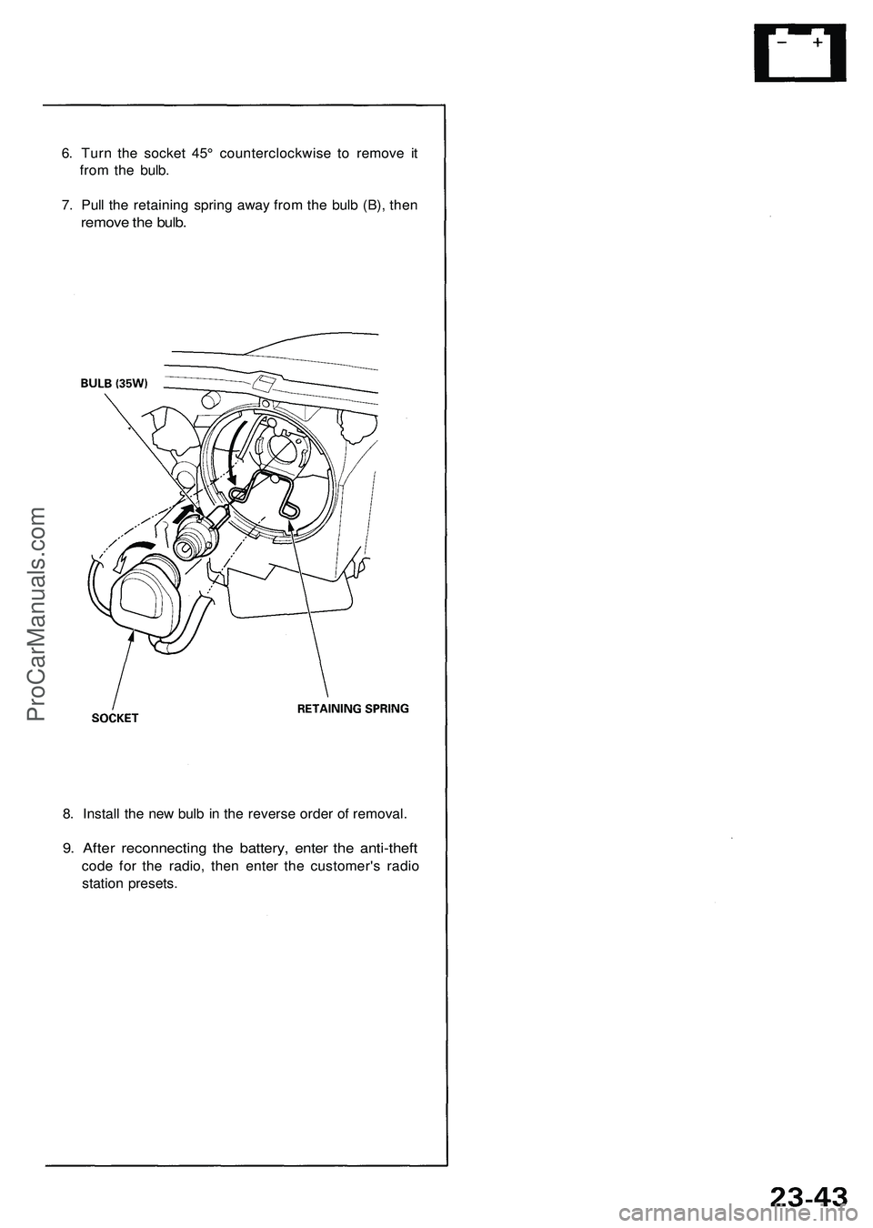
6. Turn the socket 45° counterclockwise to remove it
from the bulb.
7. Pull the retaining spring away from the bulb (B), then
remove the bulb.
8. Install the new bulb in the reverse order of removal.
9. After reconnecting the battery, enter the anti-theft
code for the radio, then enter the customer's radio
station presets.ProCarManuals.com
Page 276 of 1503
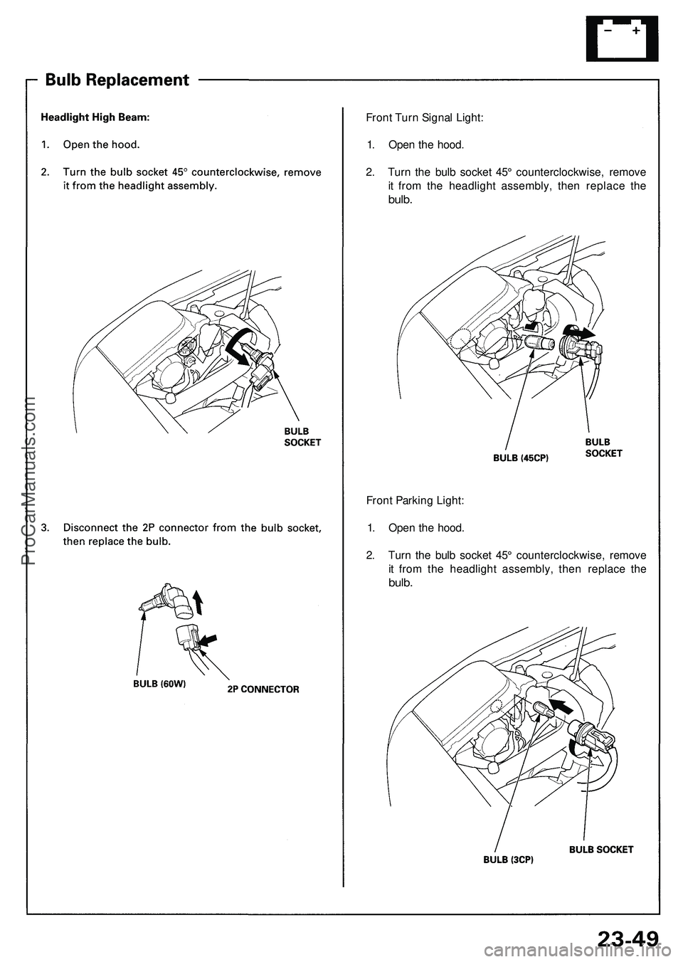
Front Turn Signal Light:
1. Open the hood.
2. Turn the bulb socket 45° counterclockwise, remove
it from the headlight assembly, then replace the
bulb.
Front Parking Light:
1. Open the hood.
2. Turn the bulb socket 45° counterclockwise, remove
it from the headlight assembly, then replace the
bulb.ProCarManuals.com
Page 368 of 1503
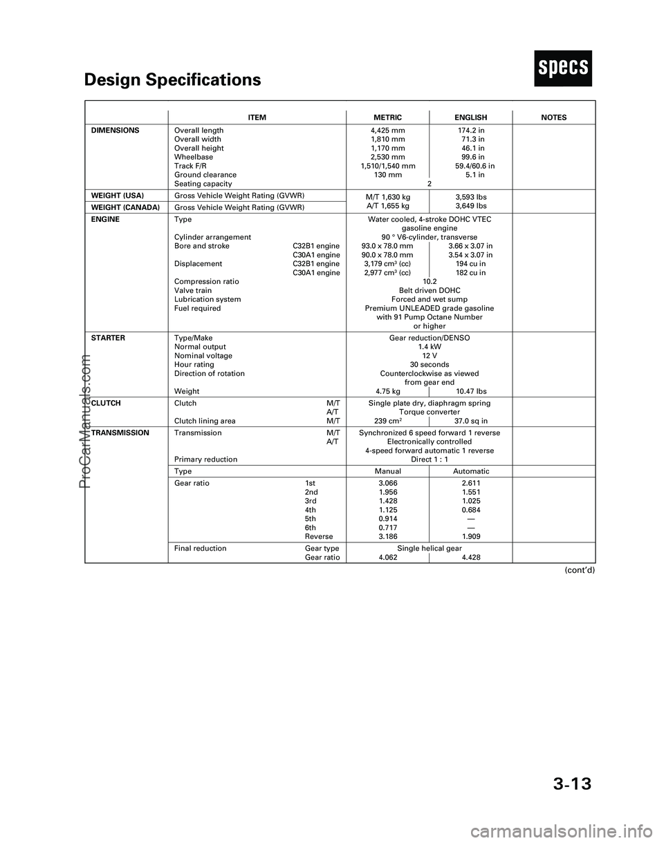
3-13
TDesign Specifications
(cont’d)
ITEMMETRICENGLISH
DIMENSIONSOverall length
Overall width
Overall height
Wheelbase
Track F/R
Ground clearance
Seating capacity4,425 mm 174.2 in
1,810 mm 71.3 in
1,170 mm 46.1 in
2,530 mm 99.6 in
1,510/1,540 mm 59.4/60.6 in
130 mm 5.1 in
2
WEIGHT (USA)
Single plate dry, diaphragm spring
Torque converter
239 cm
237.0 sq in
CLUTCHClutch M/T
A/T
Clutch lining area M/T
Gross Vehicle Weight Rating (GVWR)
NOTES
Gear reduction/DENSO
1.4 kW
12 V
30 seconds
Counterclockwise as viewed
from gear end
4.75 kg 10.47 lbs
ENGINEWater cooled, 4-stroke DOHC VTEC
gasoline engine
90 °V6-cylinder, transverse
93.0 x 78.0 mm 3.66 x 3.07 in
90.0 x 78.0 mm 3.54 x 3.07 in
3,179 cm
3(cc) 194 cu in
2,977 cm3(cc) 182 cu in
10.2
Belt driven DOHC
Forced and wet sump
Premium UNLEADED grade gasoline
with 91 Pump Octane Number
or higher
STARTERType/Make
Normal output
Nominal voltage
Hour rating
Direction of rotation
Weight
WEIGHT (CANADA)Gross Vehicle Weight Rating (GVWR)
Synchronized 6 speed forward 1 reverse
Electronically controlled
4-speed forward automatic 1 reverse
Direct 1 : 1Transmission M/T
A/T
Primary reduction
Manual AutomaticType
3.066 2.611
1.956 1.551
1.428 1.025
1.125 0.684
0.914—
0.717—
3.186 1.909Gear ratio 1st
2nd
3rd
4th
5th
6th
Reverse
Single helical gear
4.062 4.428
TRANSMISSION
Final reduction Gear type
Gear ratio
Type
Cylinder arrangement
Bore and strokeC32B1 engine
C30A1 engine
DisplacementC32B1 engine
C30A1 engine
Compression ratio
Valve train
Lubrication system
Fuel required
M/T 1,630 kg 3,593 lbs
A/T 1,655 kg 3,649 lbs
*04-NSX (61SW004)SEC03(01-16) 9/22/04 1:49 PM Page 3-13
ProCarManuals.com
Page 426 of 1503
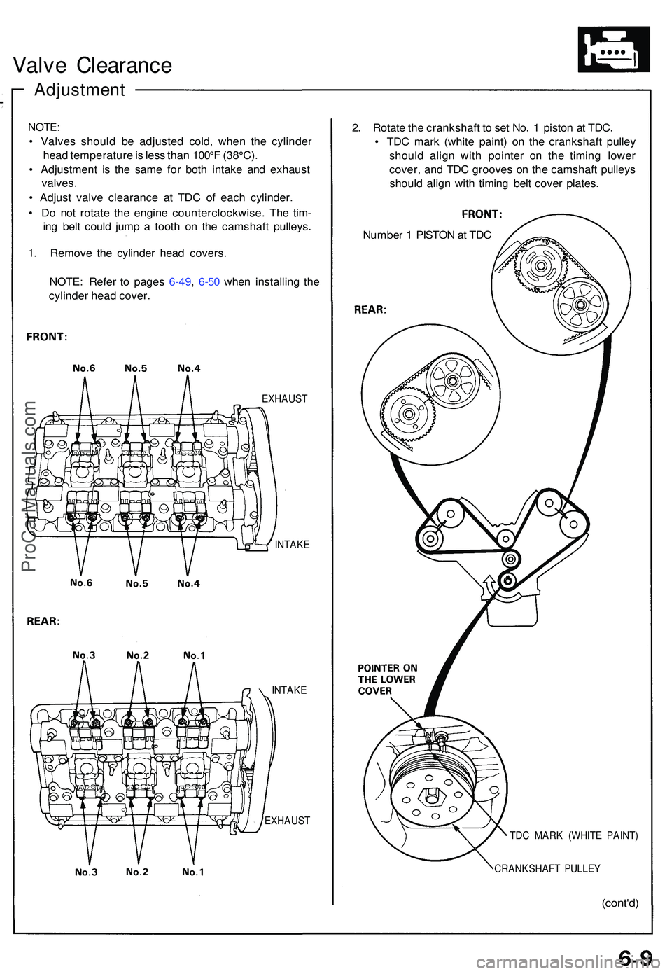
Valve Clearanc e
Adjustmen t
NOTE:
• Valve s shoul d b e adjuste d cold , whe n th e cylinde r
hea d temperatur e is les s tha n 100° F (38°C) .
• Adjustmen t i s th e sam e fo r bot h intak e an d exhaus t
valves .
• Adjus t valv e clearanc e a t TD C o f eac h cylinder .
• D o no t rotat e th e engin e counterclockwise . Th e tim -
in g bel t coul d jum p a toot h o n th e camshaf t pulleys .
1 . Remov e th e cylinde r hea d covers .
NOTE : Refe r t o page s 6-49 , 6-5 0 whe n installin g th e
cylinde r hea d cover .
EXHAUS T
INTAK E
INTAK E
EXHAUS T
2. Rotat e th e crankshaf t t o se t No . 1 pisto n a t TDC .
• TD C mar k (whit e paint ) o n th e crankshaf t pulle y
shoul d alig n wit h pointe r o n th e timin g lowe r
cover , an d TD C groove s o n th e camshaf t pulley s
shoul d alig n wit h timin g bel t cove r plates .
Numbe r 1 PISTO N a t TD C
TDC MAR K (WHIT E PAINT )
CRANKSHAF T PULLE Y
(cont'd)
ProCarManuals.com
Page 428 of 1503
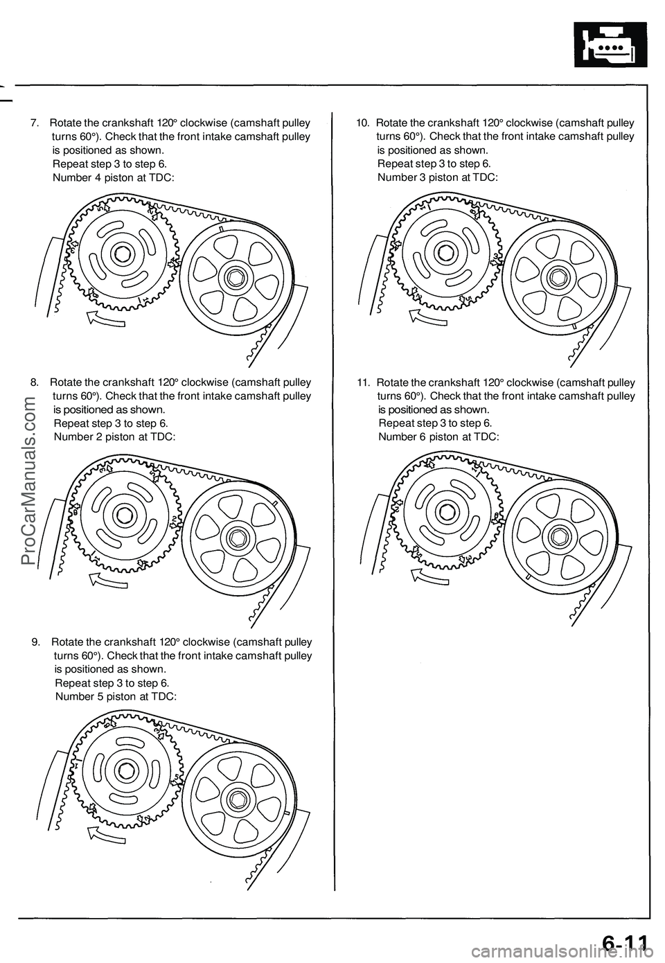
7. Rotat e th e crankshaf t 120 ° clockwis e (camshaf t pulle y
turn s 60°) . Chec k tha t th e fron t intak e camshaf t pulle y
i s positione d a s shown .
Repea t ste p 3 to ste p 6 .
Numbe r 4 pisto n a t TDC :
8 . Rotat e th e crankshaf t 120 ° clockwis e (camshaf t pulle y
turn s 60°) . Chec k tha t th e fron t intak e camshaf t pulle y
is positione d a s shown .
Repea t ste p 3 to ste p 6 .
Numbe r 2 pisto n a t TDC :
9 . Rotat e th e crankshaf t 120 ° clockwis e (camshaf t pulle y
turn s 60°) . Chec k tha t th e fron t intak e camshaf t pulle y
i s positione d a s shown .
Repea t ste p 3 to ste p 6 .
Numbe r 5 pisto n a t TDC : 10
. Rotat e th e crankshaf t 120 ° clockwis e (camshaf t pulle y
turn s 60°) . Chec k tha t th e fron t intak e camshaf t pulle y
i s positione d a s shown .
Repea t ste p 3 to ste p 6 .
Numbe r 3 pisto n a t TDC :
11 . Rotat e th e crankshaf t 120 ° clockwis e (camshaf t pulle y
turn s 60°) . Chec k tha t th e fron t intak e camshaf t pulle y
is positione d a s shown .
Repea t ste p 3 to ste p 6 .
Numbe r 6 pisto n a t TDC :
ProCarManuals.com
Page 431 of 1503
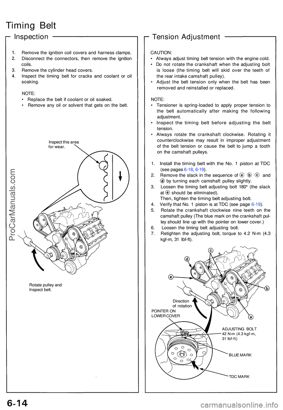
Timing Bel t
Inspectio n
Remove th e ignitio n coi l cover s an d harnes s clamps .
Disconnec t th e connectors , the n remov e th e ignitio n
coils .
Remov e th e cylinde r hea d covers .
Inspec t th e timin g bel t fo r crack s an d coolan t o r oi l
soaking .
NOTE:
• Replac e th e bel t i f coolan t o r oi l soaked .
• Remov e an y oi l o r solven t tha t get s o n th e belt .
Inspec t thi s are a
fo r wear .
Rotate pulle y an d
Inspec t belt .
Tensio n Adjustmen t
CAUTION:
• Alway s adjus t timin g bel t tensio n wit h th e engin e cold .
• D o no t rotat e th e crankshaf t whe n th e adjustin g bol t
i s loos e (th e timin g bel t wil l ski d ove r th e teet h o f
th e rea r intak e camshaf t pulley) .
• Adjus t th e bel t tensio n onl y whe n th e bel t ha s bee n
remove d an d reinstalle d o r replaced .
NOTE:
• Tensione r i s spring-loade d t o appl y prope r tensio n t o
th e bel t automaticall y afte r makin g th e followin g
adjustment .
• Inspec t th e timin g bel t befor e adjustin g th e bel t
tension .
• Alway s rotat e th e crankshaf t clockwise . Rotatin g i t
counterclockwis e ma y resul t i n imprope r adjustmen t
o f th e bel t tensio n o r caus e th e bel t t o jum p a toot h
o n th e camshaf t pulleys .
1. Instal l th e timin g bel t wit h th e No . 1 pisto n a t TD C
(see page s 6-18 , 6-19 ).
2 . Remov e th e slac k i n th e sequenc e o f an d
by turnin g eac h camshaf t pulle y slightly .
3 . Loose n th e timin g bel t adjustin g bol t 180 ° (th e slac k
at shoul d b e eliminated) .
Then, tighte n th e timin g bel t adjustin g bolt .
4. Verif y tha t No . 1 pisto n i s a t TD C (se e pag e 6-19 ).
5 . Rotat e th e crankshaf t clockwis e nin e teet h o n th e
camshaf t pulle y (Th e blu e mar k o n th e crankshaf t pul -
le y shoul d lin e u p wit h th e pointe r o n lowe r cover. )
6 . Loose n th e timin g bel t adjustin g bolt .
7 . Retighte n th e adjustin g bolt , torqu e t o 4. 2 N- m (4. 3
kgf-m , 3 1 Ibf-ft) .
Directio nof rotatio nPOINTE R O NLOWE R COVE R
ADJUSTING BOL T
42 N- m (4. 3 kgf-m ,
3 1 Ibf-ft )
BLUE MAR K
TDC MAR K
ProCarManuals.com
Page 435 of 1503
Timing Belt
Installation
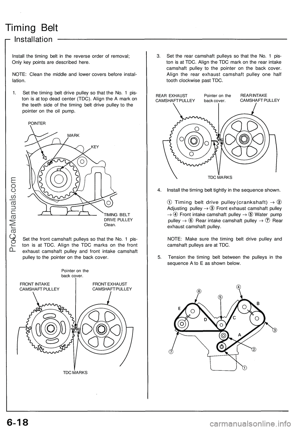
Install the timing belt in the reverse order of removal;
Only key points are described here.
NOTE: Clean the middle and lower covers before instal-
lation.
1. Set the timing belt drive pulley so that the No. 1 pis-
ton is at top dead center (TDC). Align the A mark on
the teeth side of the timing belt drive pulley to the
pointer on the oil pump.
POINTER
MARK
KEY
TIMING BELT
DRIVE PULLEY
Clean.
2. Set the front camshaft pulleys so that the No. 1 pis-
ton is at TDC. Align the TDC marks on the front
exhaust camshaft pulley and front intake camshaft
pulley to the pointer on the back cover.
Pointer on the
back cover.
FRONT INTAKE
CAMSHAFT PULLEY
FRONT EXHAUST
CAMSHAFT PULLEY
TDC MARKS
3. Set the rear camshaft pulleys so that the No. 1 pis-
ton is at TDC. Align the TDC mark on the rear intake
camshaft pulley to the pointer on the back cover.
Align the rear exhaust camshaft pulley one half
tooth clockwise past TDC.
REAR EXHAUST
CAMSHAFT PULLEY
Pointer on the
back cover.
REAR INTAKE
CAMSHAFT PULLEY
TDC MARKS
4. Install the timing belt tightly in the sequence shown.
Timing belt drive pulley (crankshaft)
Adjusting pulley Front exhaust camshaft pulley
Front intake camshaft pulley Water pump
pulley Rear intake camshaft pulley Rear
exhaust camshaft pulley.
NOTE: Make sure the timing belt drive pulley and
camshaft pulleys are at TDC.
5. Tension the timing belt between the pulleys in the
sequence A to E as shown below.ProCarManuals.com
Page 463 of 1503
Reaming
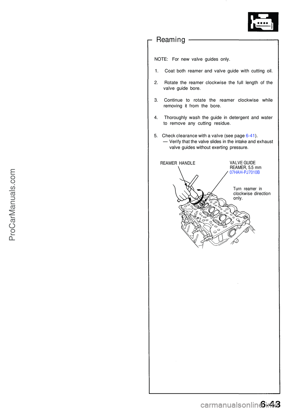
NOTE: Fo r ne w valv e guide s only .
1 . Coa t bot h reame r an d valv e guid e wit h cuttin g oil .
2 . Rotat e th e reame r clockwis e th e ful l lengt h o f th e
valv e guid e bore .
3 . Continu e t o rotat e th e reame r clockwis e whil e
removin g i t fro m th e bore .
4 . Thoroughl y was h th e guid e i n detergen t an d wate r
t o remov e an y cuttin g residue .
5 . Chec k clearanc e wit h a valv e (se e pag e 6-41 ).
— Verif y tha t th e valv e slide s in th e intak e an d exhaus t
valv e guide s withou t exertin g pressure .
REAMER HANDL E VALV
E GUID E
REAMER , 5. 5 m m
07HAH-PJ7010 B
Tur n reame r i n
clockwis e directio nonly.
ProCarManuals.com