door lock ACURA NSX 1997 Service Repair Manual
[x] Cancel search | Manufacturer: ACURA, Model Year: 1997, Model line: NSX, Model: ACURA NSX 1997Pages: 1503, PDF Size: 57.08 MB
Page 258 of 1503
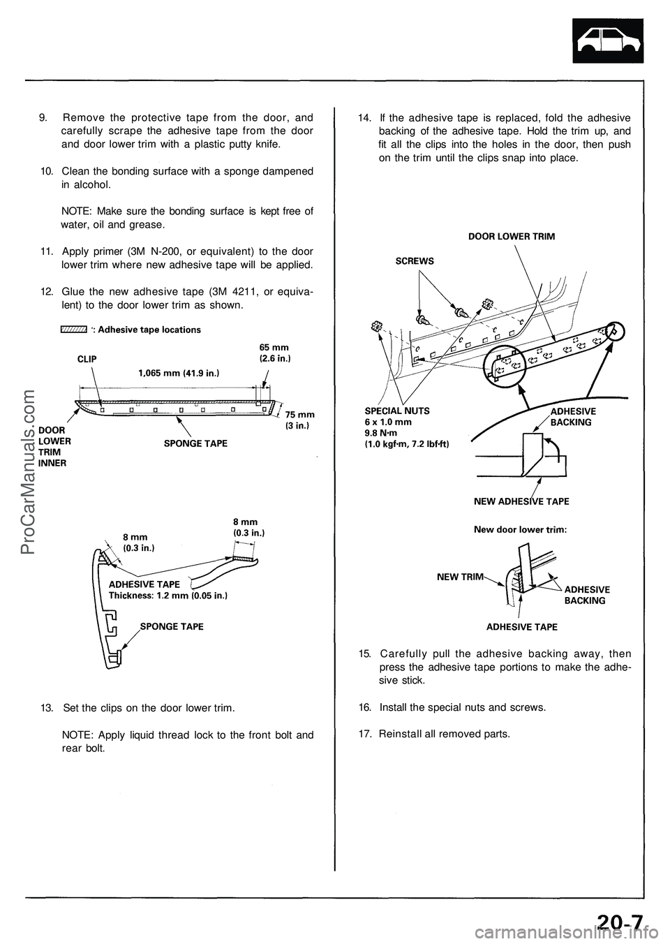
14. If the adhesive tape is replaced, fold the adhesive
backing of the adhesive tape. Hold the trim up, and
fit all the clips into the holes in the door, then push
on the trim until the clips snap into place.
15. Carefully pull the adhesive backing away, then
press the adhesive tape portions to make the adhe-
sive stick.
16. Install the special nuts and screws.
17. Reinstall all removed parts.
13. Set the clips on the door lower trim.
NOTE: Apply liquid thread lock to the front bolt and
rear bolt.
9. Remove the protective tape from the door, and
carefully scrape the adhesive tape from the door
and door lower trim with a plastic putty knife.
10. Clean the bonding surface with a sponge dampened
in alcohol.
NOTE: Make sure the bonding surface is kept free of
water, oil and grease.
11. Apply primer (3M N-200, or equivalent) to the door
lower trim where new adhesive tape will be applied.
12. Glue the new adhesive tape (3M 4211, or equiva-
lent) to the door lower trim as shown.ProCarManuals.com
Page 354 of 1503
Power Door Locks
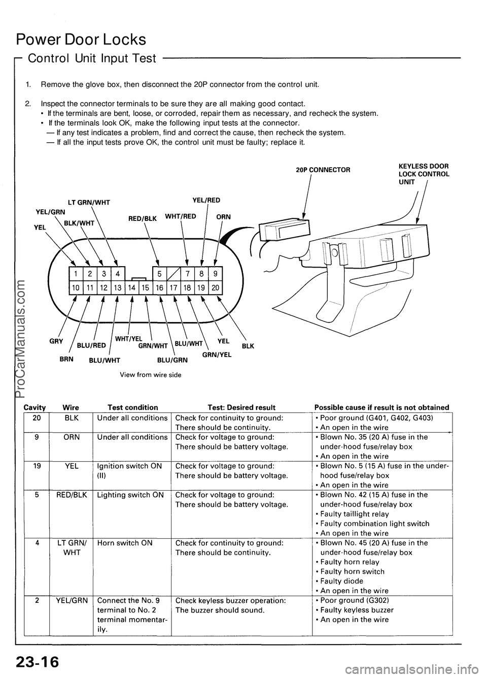
Control Unit Input Test
1. Remove the glove box, then disconnect the 20P connector from the control unit.
2. Inspect the connector terminals to be sure they are all making good contact.
• If the terminals are bent, loose, or corroded, repair them as necessary, and recheck the system.
• If the terminals look OK, make the following input tests at the connector.
— If any test indicates a problem, find and correct the cause, then recheck the system.
— If all the input tests prove OK, the control unit must be faulty; replace it.ProCarManuals.com
Page 356 of 1503
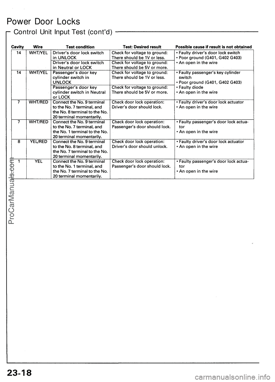
Power Door Locks
Control Unit Input Test (cont'd)ProCarManuals.com
Page 358 of 1503
Power Door Locks
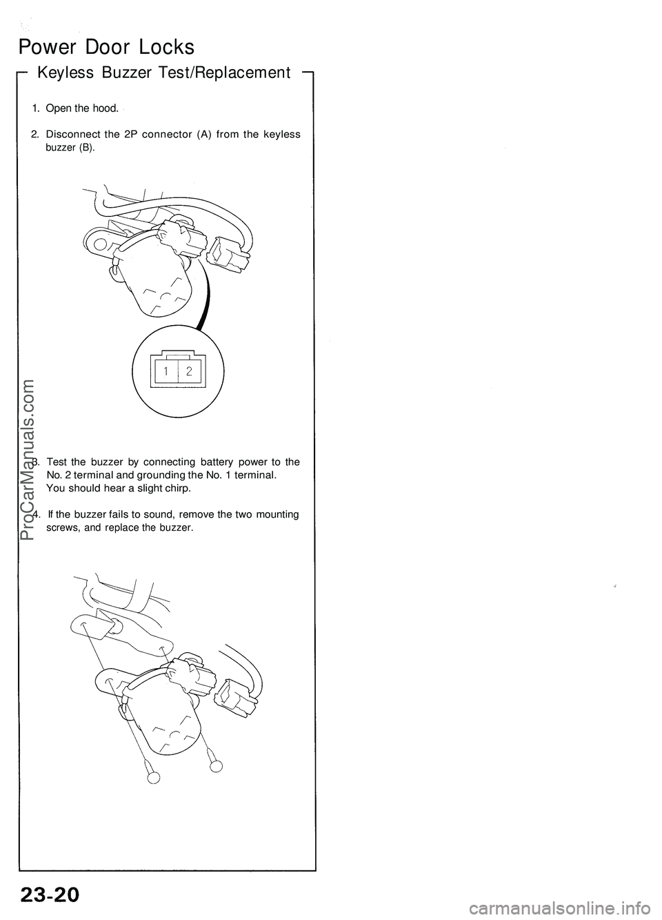
Keyless Buzzer Test/Replacement
1. Open the hood.
2. Disconnect the 2P connector (A) from the keyless
buzzer (B).
3. Test the buzzer by connecting battery power to the
No. 2 terminal and grounding the No. 1 terminal.
You should hear a slight chirp.
4. If the buzzer fails to sound, remove the two mounting
screws, and replace the buzzer.ProCarManuals.com
Page 359 of 1503
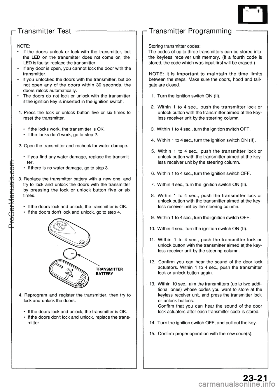
Transmitter Test
NOTE:
• If the doors unlock or lock with the transmitter, but
the LED on the transmitter does not come on, the
LED is faulty; replace the transmitter.
• If any door is open, you cannot lock the door with the
transmitter.
• If you unlocked the doors with the transmitter, but do
not open any of the doors within 30 seconds, the
doors relock automatically.
• The doors do not lock or unlock with the transmitter
if the ignition key is inserted in the ignition switch.
1. Press the lock or unlock button five or six times to
reset the transmitter.
• If the locks work, the transmitter is OK.
• If the locks don't work, go to step 2.
2. Open the transmitter and recheck for water damage.
• If you find any water damage, replace the transmit-
ter.
• If there is no water damage, go to step 3.
3. Replace the transmitter battery with a new one, and
try to lock and unlock the doors with the transmitter
by pressing the lock or unlock button five or six
times.
• If the doors lock and unlock, the transmitter is OK.
• If the doors don't lock and unlock, go to step 4.
4. Reprogram and register the transmitter, then try to
lock and unlock the doors.
• If the doors lock and unlock, the transmitter is OK.
• If the doors don't lock and unlock, replace the trans-
mitter
Transmitter Programming
Storing transmitter codes:
The codes of up to three transmitters can be stored into
the keyless receiver unit memory. (If a fourth code is
stored, the code which was input first will be erased.)
NOTE: It is important to maintain the time limits
between the steps. Make sure the doors, hood and tail-
gate are closed.
1. Turn the ignition switch ON (II).
2. Within 1 to 4 sec., push the transmitter lock or
unlock button with the transmitter aimed at the key-
less receiver unit by the steering column.
3. Within 1 to 4 sec., turn the ignition switch OFF.
4. Within 1 to 4 sec., turn the ignition switch ON (II).
5. Within 1 to 4 sec., push the transmitter lock or
unlock button with the transmitter aimed at the key-
less receiver unit by the steering column.
6. Within 1 to 4 sec., turn the ignition switch OFF.
7. Within 4 sec., turn the ignition switch ON (II).
8. Within 1 to 4 sec., push the transmitter lock or
unlock button with the transmitter aimed at the key-
less receiver unit by the steering column.
9. Within 1 to 4 sec., turn the ignition switch OFF.
10. Within 4 sec., turn the ignition switch ON (II).
11. Within 1 to 4 sec., push the transmitter lock or
unlock button with the transmitter aimed at the key-
less receiver unit by the steering column.
12. Confirm you can hear the sound of the door lock
actuators. Within 1 to 4 sec., push the transmitter
lock or unlock button again.
13. Within 10 sec., aim the transmitters (up to two addi-
tional ones) whose codes you want to store at the
keyless receiver unit, and press the transmitter lock
or unlock buttons.
Confirm that you can hear the sound of the door
lock actuators after each transmitter code is stored.
14. Turn the ignition switch OFF, and pull out the key.
15. Confirm proper operation with the new code(s).ProCarManuals.com
Page 371 of 1503
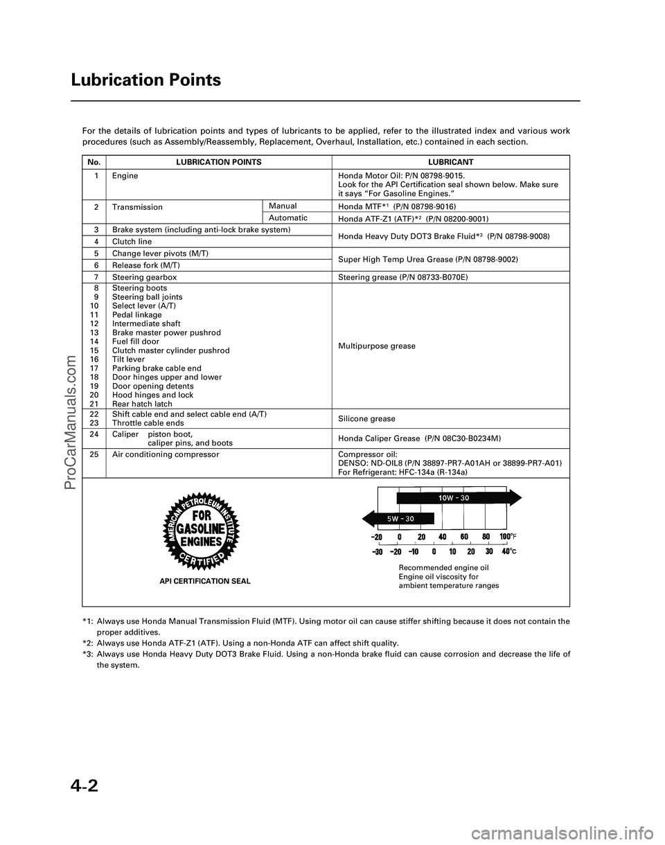
4-2
For the details of lubrication points and types of lubricants to be appl\
ied, refer to the illustrated index and various work
procedures (such as Assembly/Reassembly, Replacement, Overhaul, Install\
ation, etc.) contained in each section.
*1: Always use Honda Manual Transmission Fluid (MTF). Using motor oil can \
cause stiffer shifting because it does not contain theproper additives.
*2: Always use Honda ATF-Z1 (ATF). Using a non-Honda ATF can affect shift \
quality.
*3: Always use Honda Heavy Duty DOT3 Brake Fluid. Using a non-Honda brake fl\
uid can cause corrosion and decrease the life of the system.
Lubrication Points
No.LUBRICATION POINTSLUBRICANT
1Honda Motor Oil: P/N 08798-9015.
Look for the API Certification seal shown below. Make sure
it says “For Gasoline Engines.”
2TransmissionHonda MTF*1(P/N 08798-9016)
3Brake system (including anti-lock brake system)Honda Heavy Duty DOT3 Brake Fluid*3(P/N 08798-9008)4Clutch line
5Change lever pivots (M/T)Super High Temp Urea Grease (P/N 08798-9002)6Release fork (M/T)
8
9
10
11
12
13
14
15
16
17
18
19
20
21Steering boots
Steering ball joints
Select lever (A/T)
Pedal linkage
Intermediate shaft
Brake master power pushrod
Fuel fill door
Clutch master cylinder pushrod
Tilt lever
Parking brake cable end
Door hinges upper and lower
Door opening detents
Hood hinges and lock
Rear hatch latch
Multipurpose grease
24
22
23
Caliper piston boot, caliper pins, and boots
Shift cable end and select cable end (A/T)
Throttle cable ends
Honda Caliper Grease (P/N 08C30-B0234M)
Silicone grease
25Air conditioning compressorCompressor oil:
DENSO: ND-OIL8 (P/N 38897-PR7-A01AH or 38899-PR7-A01)
For Refrigerant: HFC-134a (R-134a)
Manual
Honda ATF-Z1 (ATF)*2(P/N 08200-9001)Automatic
7Steering gearboxSteering grease (P/N 08733-B070E)
Engine
API CERTIFICATION SEAL
Recommended engine oil
Engine oil viscosity for
ambient temperature ranges
*05-NSX (61SW004)SEC04(01-10) 9/22/04 1:49 PM Page 4-2
ProCarManuals.com
Page 1065 of 1503
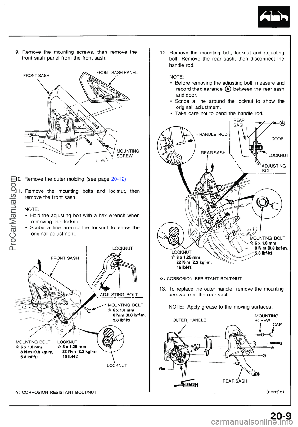
9. Remov e th e mountin g screws , the n remov e th e
fron t sas h pane l fro m th e fron t sash .
FRONT SASH FRONT SASH PANEL
MOUNTIN GSCREW
10. Remov e th e oute r moldin g (se e pag e 20-12) .
11 . Remov e th e mountin g bolt s an d locknut , the n
remov e th e fron t sash .
NOTE :
• Hol d th e adjustin g bol t wit h a he x wrenc h whe n
removin g th e locknut .
• Scrib e a lin e aroun d th e locknu t t o sho w th e
origina l adjustment .
LOCKNUT
MOUNTIN G BOL T
MOUNTIN G BOL T LOCKNU T
LOCKNUT
CORROSIO N RESISTAN T BOLT/NU T
12. Remov e th e mountin g bolt , locknu t an d adjustin g
bolt . Remov e th e rea r sash , the n disconnec t th e
handl e rod .
NOTE :
• Befor e removin g th e adjustin g bolt , measur e an d
recor d th e clearanc e betwee n th e rea r sas h
an d door .
• Scrib e a lin e aroun d th e locknu t t o sho w th e
origina l adjustment .
• Tak e car e no t t o ben d th e handl e rod .
REA RSASH
LOCKNUT
CORROSIO N RESISTAN T BOLT/NU T
13. T o replac e th e oute r handle , remov e th e mountin g
screw s fro m th e rea r sash .
NOTE : Appl y greas e t o th e movin g surfaces .
OUTER HANDL EMOUNTIN GSCREWCAP
REA R SAS H
FRON
T SAS H
ADJUSTING BOL T HANDL
E RO D
DOO R
REAR SAS H
ADJUSTING
BOLT
LOCKNU T
MOUNTIN G BOL T
ProCarManuals.com
Page 1066 of 1503
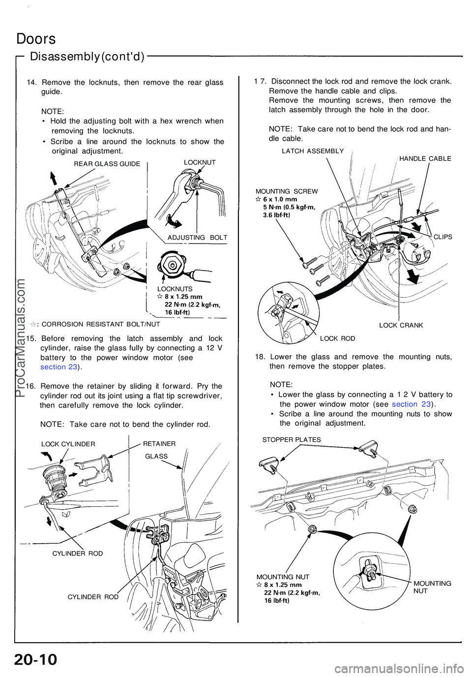
Doors
Disassembl y (cont'd )
14. Remov e th e locknuts , the n remov e th e rea r glas s
guide .
NOTE :
• Hol d th e adjustin g bol t wit h a he x wrenc h whe n
removin g th e locknuts .
• Scrib e a lin e aroun d th e locknut s t o sho w th e
origina l adjustment .
CORROSION RESISTAN T BOLT/NU T
15. Befor e removin g th e latc h assembl y an d loc k
cylinder , rais e th e glas s full y b y connectin g a 1 2 V
batter y t o th e powe r windo w moto r (se e
section 23 ).
16 . Remov e th e retaine r b y slidin g i t forward . Pr y th e
cylinde r ro d ou t it s join t usin g a fla t ti p screwdriver ,
the n carefull y remov e th e loc k cylinder .
NOTE : Tak e car e no t t o ben d th e cylinde r rod .
LOC K CYLINDE RRETAINER
CYLINDER RO D
1 7 . Disconnec t th e loc k ro d an d remov e th e loc k crank .
Remov e th e handl e cabl e an d clips .
Remov e th e mountin g screws , the n remov e th e
latc h assembl y throug h th e hol e i n th e door .
NOTE : Tak e car e no t t o ben d th e loc k ro d an d han -
dl e cable .
LATCH ASSEMBL Y
HANDLE CABL E
MOUNTIN G SCRE W
CLIPS
LOCK CRAN K
LOC K RO D
18. Lowe r th e glas s an d remov e th e mountin g nuts ,
the n remov e th e stoppe r plates .
NOTE:
• Lowe r th e glas s b y connectin g a 1 2 V batter y t o
th e powe r windo w moto r (se e sectio n 23 ).
• Scrib e a lin e aroun d th e mountin g nut s t o sho w
th e origina l adjustment .
STOPPER PLATE S
MOUNTIN G NU TMOUNTIN GNUT
REA R GLAS S GUID E LOCKNU
T
ADJUSTIN G BOL T
GLAS S
CYLINDE R RO D LOCKNUT
S
ProCarManuals.com
Page 1067 of 1503
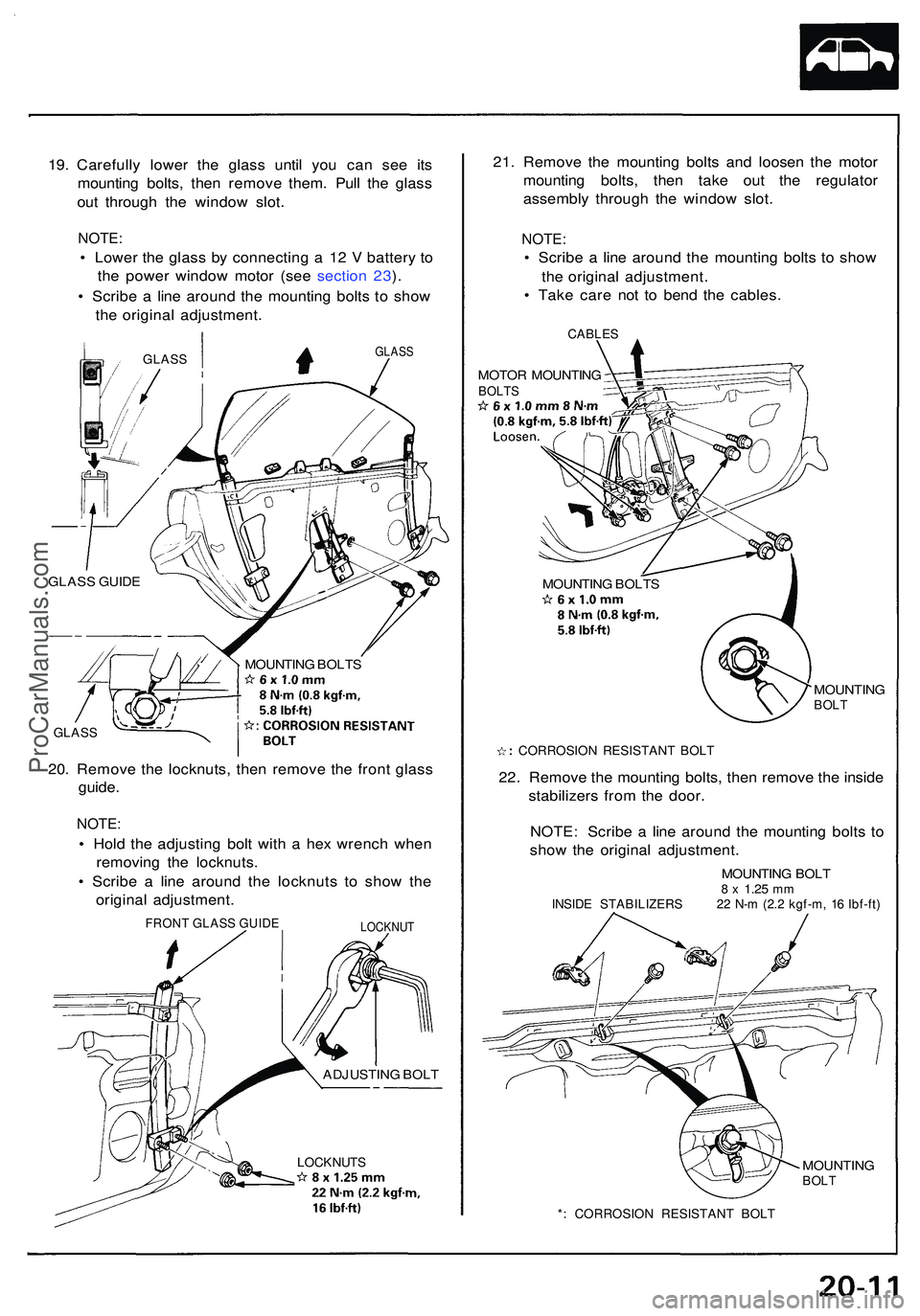
19. Carefull y lowe r th e glas s unti l yo u ca n se e it s
mountin g bolts , the n remov e them . Pul l th e glas s
ou t throug h th e windo w slot .
NOTE :
• Lowe r th e glas s b y connectin g a 1 2 V batter y t o
th e powe r windo w moto r (se e sectio n 23 ).
• Scrib e a lin e aroun d th e mountin g bolt s t o sho w
th e origina l adjustment .
GLASS
GLAS S GUID E
GLAS S
MOUNTIN G BOLT S
20. Remov e th e locknuts , the n remov e th e fron t glas s
guide .
NOTE :
• Hol d th e adjustin g bol t wit h a he x wrenc h whe n
removin g th e locknuts .
• Scrib e a lin e aroun d th e locknut s t o sho w th e
origina l adjustment .
LOCKNUTS
21. Remov e th e mountin g bolt s an d loose n th e moto r
mountin g bolts , the n tak e ou t th e regulato r
assembl y throug h th e windo w slot .
NOTE :
• Scrib e a lin e aroun d th e mountin g bolt s t o sho w
th e origina l adjustment .
• Tak e car e no t t o ben d th e cables .
CABLES
MOTOR MOUNTIN GBOLTS
MOUNTIN G BOLT S
MOUNTING
BOLT
CORROSIO N RESISTAN T BOL T
22. Remov e th e mountin g bolts , the n remov e th e insid e
stabilizer s fro m th e door .
NOTE : Scrib e a lin e aroun d th e mountin g bolt s t o
sho w th e origina l adjustment .
MOUNTING BOL T8 x 1.2 5 mmINSID E STABILIZER S 2 2 N- m (2. 2 kgf-m , 1 6 Ibf-ft )
MOUNTIN GBOLT
*: CORROSIO N RESISTAN T BOL T
GLAS S
FRON T GLAS S GUID ELOCKNU T
ADJUSTIN G BOL T
ProCarManuals.com
Page 1072 of 1503
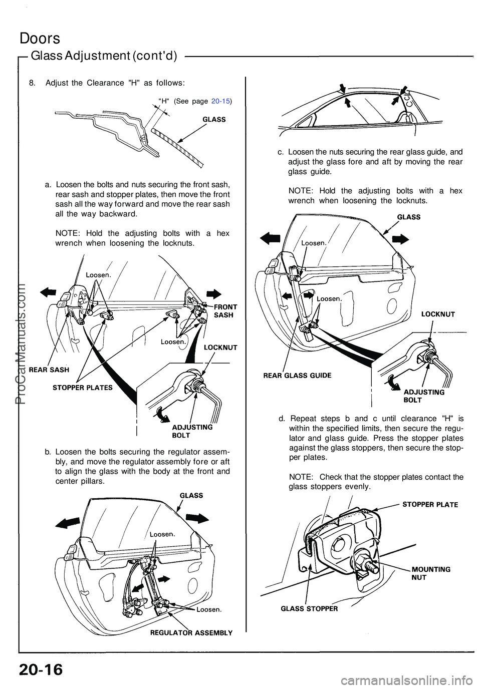
Doors
Glass Adjustmen t (cont'd )
a. Loose n th e bolt s an d nut s securin g th e fron t sash ,
rea r sas h an d stoppe r plates , the n mov e th e fron t
sas h al l th e wa y forwar d an d mov e th e rea r sas h
al l th e wa y backward .
NOTE : Hol d th e adjustin g bolt s wit h a he x
wrenc h whe n loosenin g th e locknuts .
b . Loose n th e bolt s securin g th e regulato r assem -
bly , an d mov e th e regulato r assembl y for e o r af t
t o alig n th e glas s with the bod y a t th e fron t an d
cente r pillars . c
. Loose n th e nut s securin g th e rea r glas s guide , an d
adjus t th e glas s for e an d af t b y movin g th e rea r
glas s guide .
NOTE : Hol d th e adjustin g bolt s with a he x
wrenc h whe n loosenin g th e locknuts .
d . Repea t step s b an d c unti l clearanc e "H " i s
withi n th e specifie d limits , the n secur e th e regu -
lato r an d glas s guide . Pres s th e stoppe r plate s
agains t th e glas s stoppers , the n secur e th e stop -
pe r plates .
NOTE : Chec k tha t th e stoppe r plate s contac t th e
glas s stopper s evenly .
8
. Adjus t th e Clearanc e "H " a s follows :
"H" (Se e pag e 20-15 )
ProCarManuals.com