timing belt ACURA NSX 1997 Service Repair Manual
[x] Cancel search | Manufacturer: ACURA, Model Year: 1997, Model line: NSX, Model: ACURA NSX 1997Pages: 1503, PDF Size: 57.08 MB
Page 375 of 1503
4-6
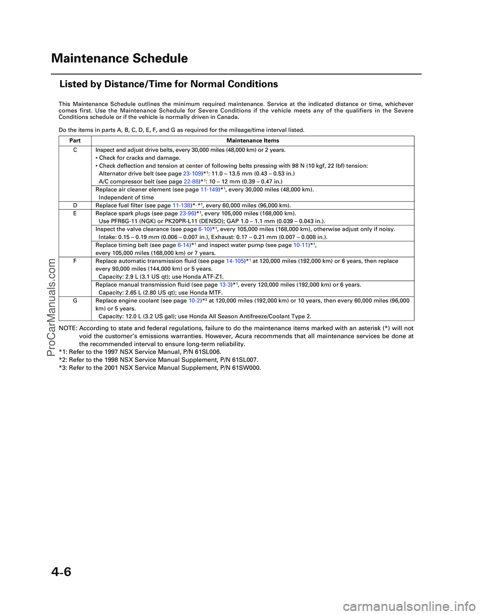
This Maintenance Schedule outlines the minimum required maintenance. Ser\
vice at the indicated distance or time, whichever
comes first. Use the Maintenance Schedule for Severe Conditions if the v\
ehicle meets any of the qualifiers in the Severe
Conditions schedule or if the vehicle is normally driven in Canada.
Do the items in parts A, B, C, D, E, F, and G as required for the mileag\
e/time interval listed.
NOTE: According to state and federal regulations, failure to do the maintenanc\
e items marked with an asterisk (*) will not
void the customer ’s emissions warranties. However, Acura recommends that all maintenance s\
ervices be done at
the recommended interval to ensure long-term reliability.
*1: Refer to the 1997 NSX Service Manual, P/N 61SL006.
*2: Refer to the 1998 NSX Service Manual Supplement, P/N 61SL007.
*3: Refer to the 2001 NSX Service Manual Supplement, P/N 61SW000.
C
D
E
F
G Inspect and adjust drive belts, every 30,000 miles (48,000 km) or 2 ye\
ars.
•
Check for cracks and damage.
• Check deflection and tension at center of following belts pressing with\
98 N (10 kgf, 22 lbf) tension:
Alternator drive belt (see page 23-109)*
1: 11.0 – 13.5 mm (0.43 – 0.53 in.)
A/C compressor belt (see page 22-88)*1: 10 – 12 mm (0.39 – 0.47 in.)
Replace air cleaner element (see page 11-149)*1, every 30,000 miles (48,000 km).
Independent of time
Replace fuel filter (see page 11-138)*, *1, every 60,000 miles (96,000 km).
Replace spark plugs (see page 23-96)*1, every 105,000 miles (168,000 km).
Use PFR6G-11 (NGK) or PK20PR-L11 (DENSO); GAP 1.0 – 1.1 mm (0.039 – 0.043 in.).
Inspect the valve clearance (see page 6-10)*1, every 105,000 miles (168,000 km), otherwise adjust only if noisy.
Intake: 0.15 – 0.19 mm (0.006 – 0.007 in.), Exhaust: 0.17 – 0.21 mm (0.007 – 0.008 in.).
Replace timing belt (see page 6-14)*1 and inspect water pump (see page 10-11)*1,
every 105,000 miles (168,000 km) or 7 years.
Replace automatic transmission fluid (see page 14-105)*1 at 120,000 miles (192,000 km) or 6 years, then replace
every 90,000 miles (144,000 km) or 5 years.
Capacity: 2.9 L (3.1 US qt); use Honda ATF-Z1.
Replace manual transmission fluid (see page 13-3)*1, every 120,000 miles (192,000 km) or 6 years.
Capacity: 2.65 L (2.80 US qt); use Honda MTF.
Replace engine coolant (see page 10-2 )*3 at 120,000 miles (192,000 km) or 10 years, then every 60,000 miles (9\
6,000
km) or 5 years. Capacity: 12.0 L (3.2 US gal); use Honda All Season Antifreeze/Coolant\
Type 2.
Part Maintenance Items
Maintenance Schedule
Listed by Distance/Time for Normal Conditions
*05-NSX (61SW004)SEC04(01-10) 9/22/04 1:49 PM Page 4-6
ProCarManuals.com
Page 430 of 1503
Timing Bel t
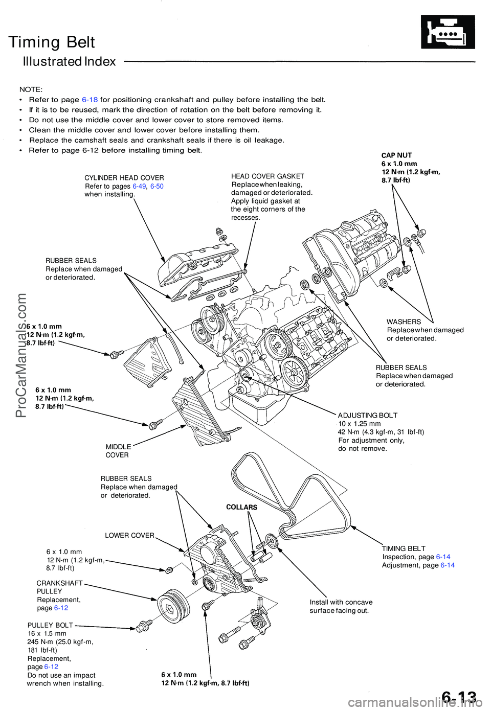
Illustrate d Inde x
NOTE :
• Refe r t o pag e 6-1 8 fo r positionin g crankshaf t an d pulle y befor e installin g th e belt .
• I f i t i s t o b e reused , mar k th e directio n o f rotatio n o n th e bel t befor e removin g it .
• D o no t us e th e middl e cove r an d lowe r cove r t o stor e remove d items .
• Clea n th e middl e cove r an d lowe r cove r befor e installin g them .
• Replac e th e camshaf t seal s an d crankshaf t seal s i f ther e i s oi l leakage .
• Refe r t o pag e 6-1 2 befor e installin g timin g belt .
CYLINDE R HEA D COVE RRefer t o page s 6-49 , 6-5 0whe n installing .
HEAD COVE R GASKE TReplace whe n leaking ,
damage d o r deteriorated .
Appl y liqui d gaske t a t
th e eigh t corner s o f th e
recesses .
RUBBER SEAL SReplac e whe n damage dor deteriorated .
WASHERSReplace whe n damage d
o r deteriorated .
RUBBER SEAL SReplac e whe n damage dor deteriorated .
MIDDLECOVER
RUBBE R SEAL SReplac e whe n damage dor deteriorated . ADJUSTIN
G BOL T
10 x 1.2 5 mm42 N- m (4. 3 kgf-m , 3 1 Ibf-ft )For adjustmen t only ,
d o no t remove .
LOWER COVE R
6 x 1. 0 m m12 N- m (1. 2 kgf-m ,8.7 Ibf-ft )
CRANKSHAF TPULLEYReplacement ,page 6-1 2
PULLE Y BOL T16 x 1. 5 m m245 N- m (25. 0 kgf-m ,181 Ibf-ft )Replacement ,page 6-1 2Do no t us e a n impac t
wrenc h whe n installing . TIMIN
G BEL T
Inspection , pag e 6-1 4
Adjustment , pag e 6-1 4
Instal l wit h concav e
surfac e facin g out .
ProCarManuals.com
Page 431 of 1503
Timing Bel t
Inspectio n
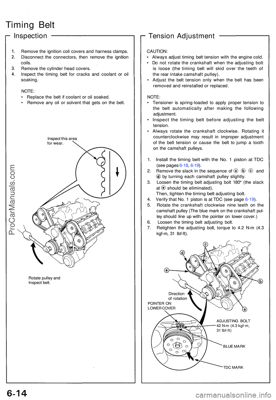
Remove th e ignitio n coi l cover s an d harnes s clamps .
Disconnec t th e connectors , the n remov e th e ignitio n
coils .
Remov e th e cylinde r hea d covers .
Inspec t th e timin g bel t fo r crack s an d coolan t o r oi l
soaking .
NOTE:
• Replac e th e bel t i f coolan t o r oi l soaked .
• Remov e an y oi l o r solven t tha t get s o n th e belt .
Inspec t thi s are a
fo r wear .
Rotate pulle y an d
Inspec t belt .
Tensio n Adjustmen t
CAUTION:
• Alway s adjus t timin g bel t tensio n wit h th e engin e cold .
• D o no t rotat e th e crankshaf t whe n th e adjustin g bol t
i s loos e (th e timin g bel t wil l ski d ove r th e teet h o f
th e rea r intak e camshaf t pulley) .
• Adjus t th e bel t tensio n onl y whe n th e bel t ha s bee n
remove d an d reinstalle d o r replaced .
NOTE:
• Tensione r i s spring-loade d t o appl y prope r tensio n t o
th e bel t automaticall y afte r makin g th e followin g
adjustment .
• Inspec t th e timin g bel t befor e adjustin g th e bel t
tension .
• Alway s rotat e th e crankshaf t clockwise . Rotatin g i t
counterclockwis e ma y resul t i n imprope r adjustmen t
o f th e bel t tensio n o r caus e th e bel t t o jum p a toot h
o n th e camshaf t pulleys .
1. Instal l th e timin g bel t wit h th e No . 1 pisto n a t TD C
(see page s 6-18 , 6-19 ).
2 . Remov e th e slac k i n th e sequenc e o f an d
by turnin g eac h camshaf t pulle y slightly .
3 . Loose n th e timin g bel t adjustin g bol t 180 ° (th e slac k
at shoul d b e eliminated) .
Then, tighte n th e timin g bel t adjustin g bolt .
4. Verif y tha t No . 1 pisto n i s a t TD C (se e pag e 6-19 ).
5 . Rotat e th e crankshaf t clockwis e nin e teet h o n th e
camshaf t pulle y (Th e blu e mar k o n th e crankshaf t pul -
le y shoul d lin e u p wit h th e pointe r o n lowe r cover. )
6 . Loose n th e timin g bel t adjustin g bolt .
7 . Retighte n th e adjustin g bolt , torqu e t o 4. 2 N- m (4. 3
kgf-m , 3 1 Ibf-ft) .
Directio nof rotatio nPOINTE R O NLOWE R COVE R
ADJUSTING BOL T
42 N- m (4. 3 kgf-m ,
3 1 Ibf-ft )
BLUE MAR K
TDC MAR K
ProCarManuals.com
Page 433 of 1503
Timing Bel t
Remova l (cont'd )
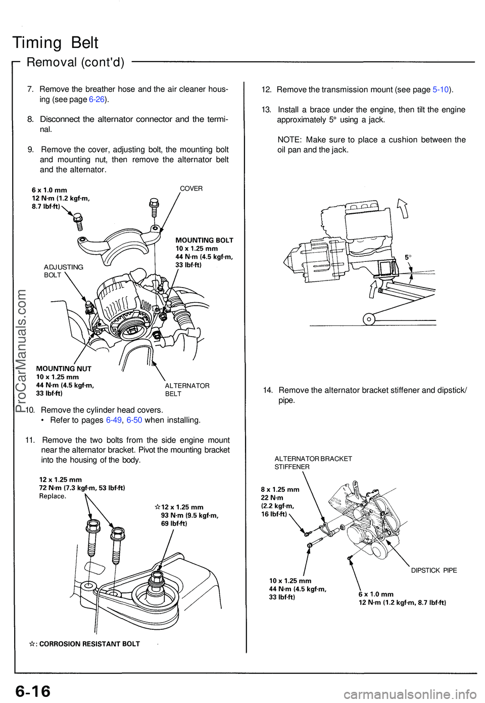
7. Remov e th e breathe r hos e an d th e ai r cleaner hous-
in g (se e pag e 6-26 ).
8 . Disconnec t th e alternato r connecto r an d th e termi -
nal.
9. Remov e th e cover , adjustin g bolt , th e mountin g bol t
an d mountin g nut , the n remov e th e alternato r bel t
an d th e alternator .
COVER
ADJUSTIN GBOLT
ALTERNATO RBELT
12. Remov e th e transmissio n moun t (se e pag e 5-10 ).
13 . Instal l a brac e unde r th e engine , the n til t th e engin e
approximatel y 5 ° usin g a jack .
NOTE : Mak e sur e t o plac e a cushio n betwee n th e
oi l pa n an d th e jack .
14 . Remov e th e alternato r bracke t stiffene r an d dipstick /
pipe .
ALTERNATO R BRACKE TSTIFFENE R
DIPSTICK PIP E
10. Remov e th e cylinde r hea d covers .
• Refe r t o page s 6-49 , 6-5 0 whe n installing .
11 . Remov e th e tw o bolt s fro m th e sid e engin e moun t
nea r th e alternato r bracket . Pivo t th e mountin g bracke t
int o th e housin g o f th e body .
ProCarManuals.com
Page 435 of 1503
Timing Belt
Installation
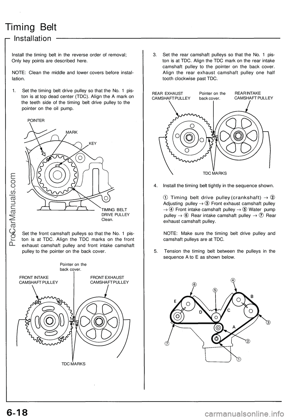
Install the timing belt in the reverse order of removal;
Only key points are described here.
NOTE: Clean the middle and lower covers before instal-
lation.
1. Set the timing belt drive pulley so that the No. 1 pis-
ton is at top dead center (TDC). Align the A mark on
the teeth side of the timing belt drive pulley to the
pointer on the oil pump.
POINTER
MARK
KEY
TIMING BELT
DRIVE PULLEY
Clean.
2. Set the front camshaft pulleys so that the No. 1 pis-
ton is at TDC. Align the TDC marks on the front
exhaust camshaft pulley and front intake camshaft
pulley to the pointer on the back cover.
Pointer on the
back cover.
FRONT INTAKE
CAMSHAFT PULLEY
FRONT EXHAUST
CAMSHAFT PULLEY
TDC MARKS
3. Set the rear camshaft pulleys so that the No. 1 pis-
ton is at TDC. Align the TDC mark on the rear intake
camshaft pulley to the pointer on the back cover.
Align the rear exhaust camshaft pulley one half
tooth clockwise past TDC.
REAR EXHAUST
CAMSHAFT PULLEY
Pointer on the
back cover.
REAR INTAKE
CAMSHAFT PULLEY
TDC MARKS
4. Install the timing belt tightly in the sequence shown.
Timing belt drive pulley (crankshaft)
Adjusting pulley Front exhaust camshaft pulley
Front intake camshaft pulley Water pump
pulley Rear intake camshaft pulley Rear
exhaust camshaft pulley.
NOTE: Make sure the timing belt drive pulley and
camshaft pulleys are at TDC.
5. Tension the timing belt between the pulleys in the
sequence A to E as shown below.ProCarManuals.com
Page 437 of 1503
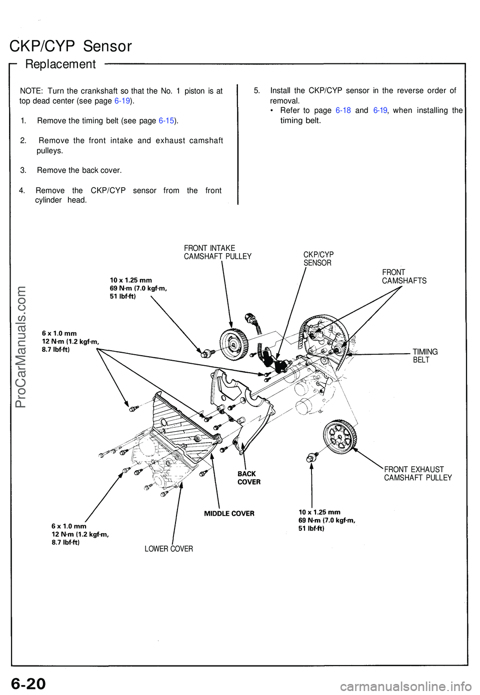
CKP/CYP Senso r
Replacemen t
NOTE: Tur n th e crankshaf t s o tha t th e No . 1 pisto n i s a t
to p dea d cente r (se e pag e 6-19 ).
1 . Remov e th e timin g bel t (se e pag e 6-15 ).
2 . Remov e th e fron t intak e an d exhaus t camshaf t
pulleys .
3 . Remov e th e bac k cover .
4 . Remov e th e CKP/CY P senso r fro m th e fron t
cylinde r head . 5
. Instal l th e CKP/CY P senso r i n th e revers e orde r o f
removal .
• Refe r t o pag e 6-1 8 an d 6-19 , whe n installin g th e
timin g belt .
FRON T INTAK ECAMSHAF T PULLE YCKP/CY PSENSOR
LOWER COVE R
FRONTCAMSHAFT S
TIMINGBELT
FRON T EXHAUS TCAMSHAF T PULLE Y
ProCarManuals.com
Page 470 of 1503
Camshafts
Installation (cont'd)
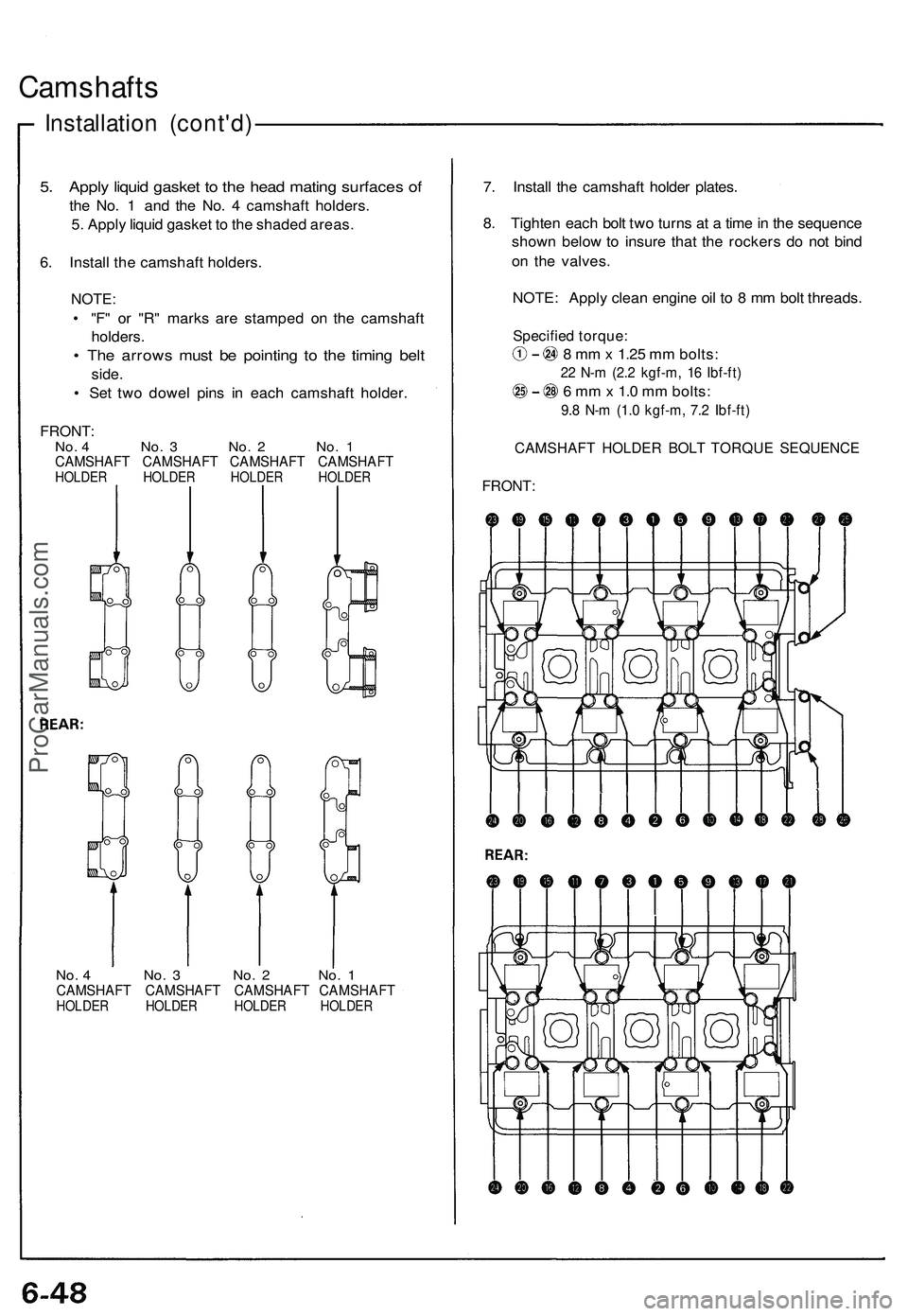
5. Apply liquid gasket to the head mating surfaces of
the No. 1 and the No. 4 camshaft holders.
5. Apply liquid gasket to the shaded areas.
6. Install the camshaft holders.
NOTE:
• "F" or "R" marks are stamped on the camshaft
holders.
• The arrows must be pointing to the timing belt
side.
• Set two dowel pins in each camshaft holder.
FRONT:
No. 4 No. 3 No. 2 No. 1
CAMSHAFT CAMSHAFT CAMSHAFT CAMSHAFT
HOLDER HOLDER HOLDER HOLDER
No. 4 No. 3 No. 2 No. 1
CAMSHAFT CAMSHAFT CAMSHAFT CAMSHAFT
HOLDER HOLDER HOLDER HOLDER
7. Install the camshaft holder plates.
8. Tighten each bolt two turns at a time in the sequence
shown below to insure that the rockers do not bind
on the valves.
NOTE: Apply clean engine oil to 8 mm bolt threads.
Specified torque:
8 mm x 1.25 mm bolts:
22 N-m (2.2 kgf-m, 16 Ibf-ft)
6 mm x 1.0 mm bolts:
9.8 N-m (1.0 kgf-m, 7.2 Ibf-ft)
CAMSHAFT HOLDER BOLT TORQUE SEQUENCE
FRONT:ProCarManuals.com
Page 495 of 1503
Crankshaft
Installation
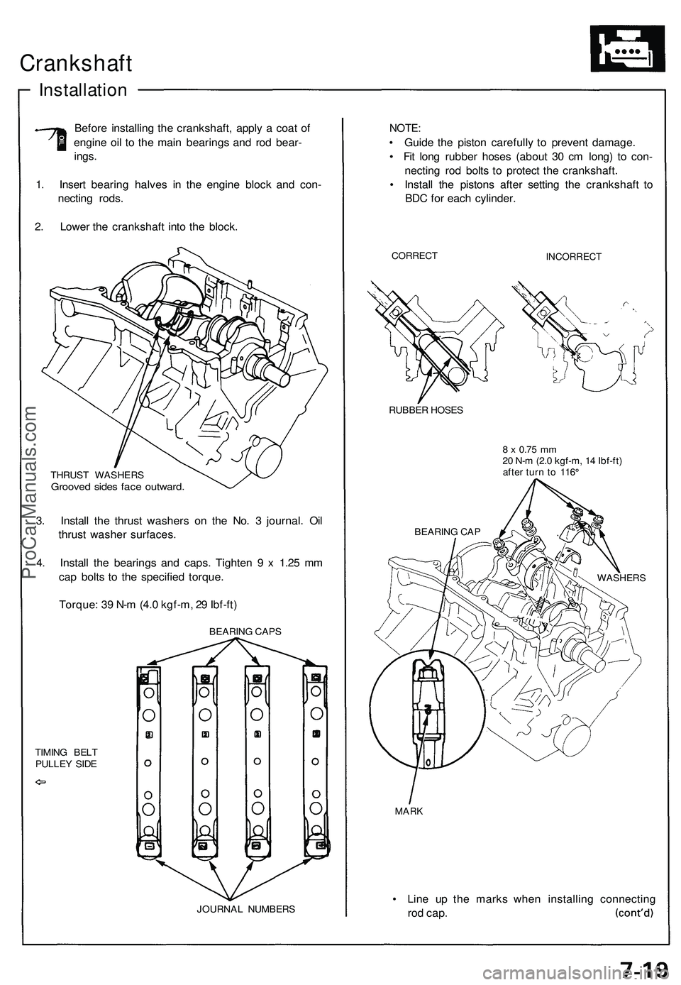
Before installing the crankshaft, apply a coat of
engine oil to the main bearings and rod bear-
ings.
1. Insert bearing halves in the engine block and con-
necting rods.
2. Lower the crankshaft into the block.
THRUST WASHERS
Grooved sides face outward.
3. Install the thrust washers on the No. 3 journal. Oil
thrust washer surfaces.
4. Install the bearings and caps. Tighten 9 x 1.25 mm
cap bolts to the specified torque.
Torque: 39 N-m (4.0 kgf-m, 29 Ibf-ft)
TIMING BELT
PULLEY SIDE
JOURNAL NUMBERS
NOTE:
• Guide the piston carefully to prevent damage.
• Fit long rubber hoses (about 30 cm long) to con-
necting rod bolts to protect the crankshaft.
• Install the pistons after setting the crankshaft to
BDC for each cylinder.
CORRECT
INCORRECT
RUBBER HOSES
8 x
0.75
mm
20 N-m (2.0 kgf-m, 14 Ibf-ft)
after turn to 116°
MARK
• Line up the marks when installing connecting
rod
cap.
BEARING CAP
WASHERS
BEARING CAPSProCarManuals.com