trunk ACURA NSX 1997 Service Repair Manual
[x] Cancel search | Manufacturer: ACURA, Model Year: 1997, Model line: NSX, Model: ACURA NSX 1997Pages: 1503, PDF Size: 57.08 MB
Page 261 of 1503
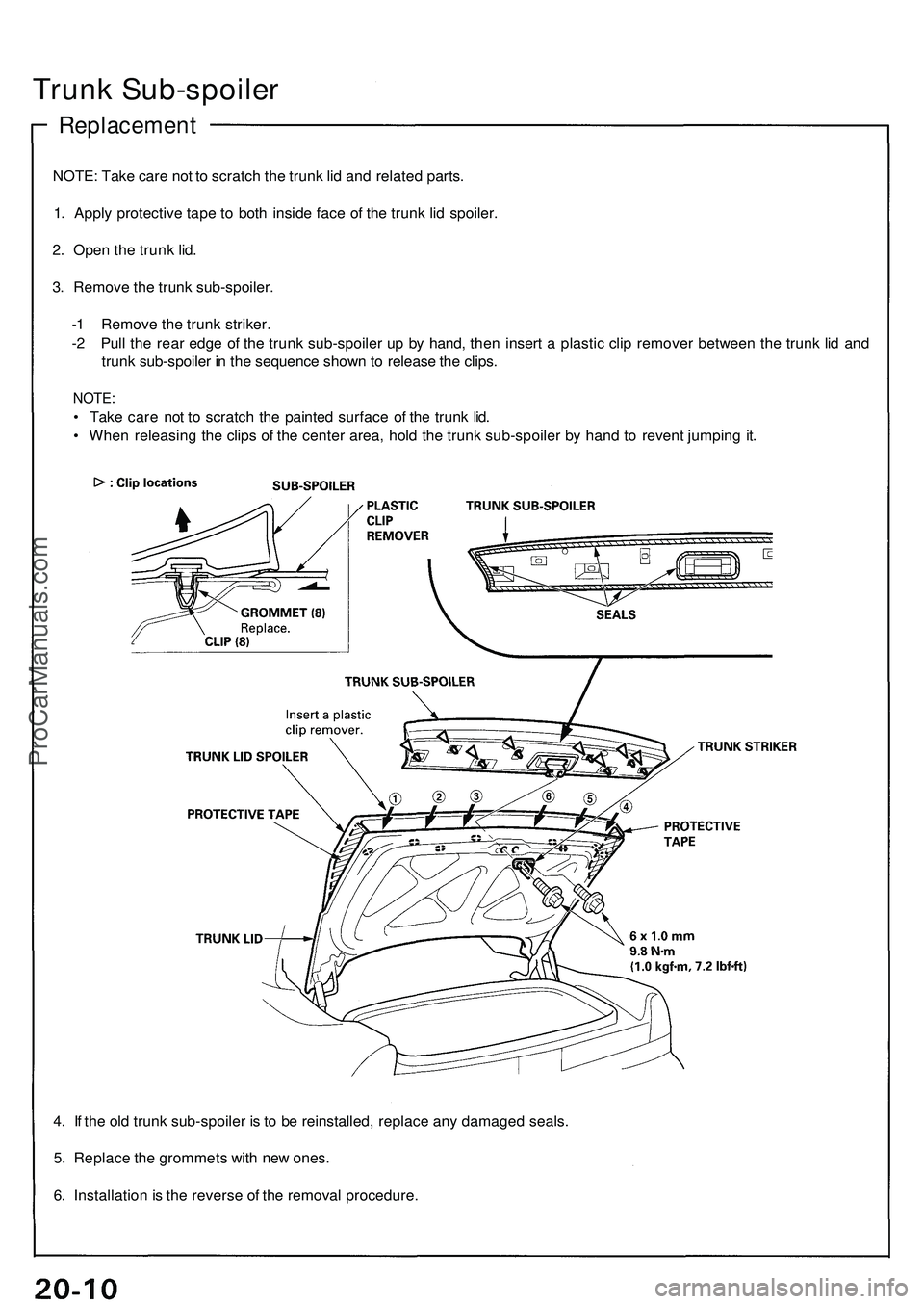
4. I f th e ol d trun k sub-spoile r i s t o b e reinstalled , replac e an y damage d seals .
5 . Replac e th e grommet s wit h ne w ones .
6 . Installatio n is th e revers e o f th e remova l procedure .
Trunk Sub-spoile r
Replacemen t
NOTE: Tak e car e no t t o scratc h th e trun k li d an d relate d parts .
1 . Appl y protectiv e tap e t o bot h insid e fac e o f th e trun k li d spoiler .
2 . Ope n th e trun k lid .
3 . Remov e th e trun k sub-spoiler .
- 1 Remov e th e trun k striker .
- 2 Pul l th e rea r edg e o f th e trun k sub-spoile r u p b y hand , the n inser t a plasti c cli p remove r betwee n th e trun k li d an d
trun k sub-spoile r i n th e sequenc e shown to releas e th e clips .
NOTE :
• Tak e car e no t t o scratc h th e painte d surfac e o f th e trun k lid .
• Whe n releasin g th e clip s o f th e cente r area , hol d th e trun k sub-spoile r b y han d t o reven t jumpin g it .
ProCarManuals.com
Page 277 of 1503
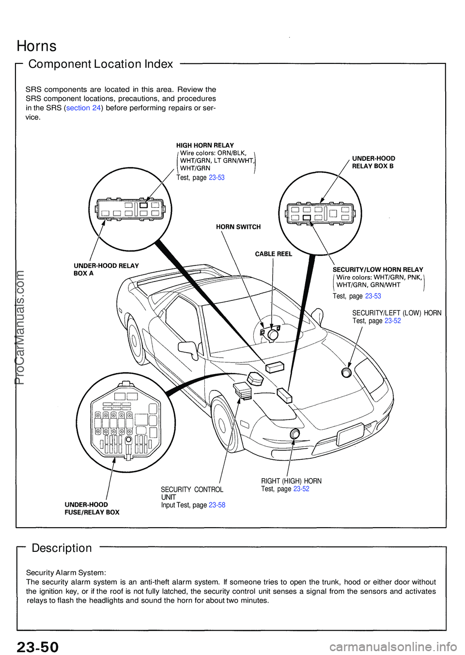
Description
Security Alar m System :
Th e securit y alar m syste m is a n anti-thef t alar m system . I f someon e trie s t o ope n th e trunk , hoo d o r eithe r doo r withou t
th e ignitio n key , o r i f th e roo f i s no t full y latched , th e securit y contro l uni t sense s a signa l fro m th e sensor s an d activate s
relay s t o flas h th e headlight s an d soun d th e hor n fo r abou t tw o minutes .
SECURIT Y CONTRO LUNITInpu t Test , pag e 23-5 8
RIGH T (HIGH ) HOR N
Test , pag e 23-5 2
Horn s
Componen t Locatio n Inde x
SRS component s ar e locate d i n thi s area . Revie w th e
SR S componen t locations , precautions , an d procedure s
i n th e SR S (sectio n 24 ) befor e performin g repair s o r ser -
vice .
Test , pag e 23-5 3
Test, pag e 23-5 3
SECURITY/LEF T (LOW ) HOR N
Test , pag e 23-5 2
ProCarManuals.com
Page 315 of 1503
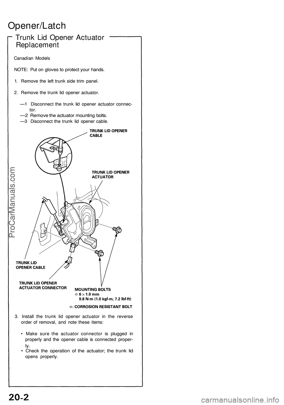
Opener/Latch
Trunk Lid Opener Actuator
Replacement
Canadian Models
NOTE: Put on gloves to protect your hands.
1. Remove the left trunk side trim panel.
2. Remove the trunk lid opener actuator.
—1 Disconnect the trunk lid opener actuator connec-
tor.
—2 Remove the actuator mounting bolts.
—3 Disconnect the trunk lid opener cable.
3. Install the trunk lid opener actuator in the reverse
order of removal, and note these items:
• Make sure the actuator connector is plugged in
properly and the opener cable is connected proper-
ly.
• Check the operation of the actuator; the trunk lid
opens properly.ProCarManuals.com
Page 363 of 1503
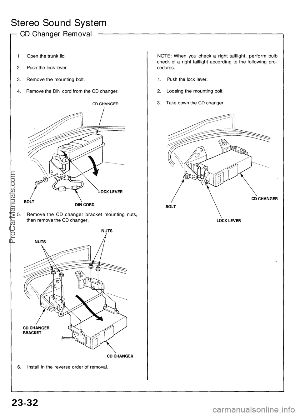
Stereo Sound System
CD Changer Removal
1. Open the trunk lid.
2. Push the lock lever.
3. Remove the mounting bolt.
4. Remove the DIN cord from the CD changer.
CD CHANGER
5. Remove the CD changer bracket mounting nuts,
then remove the CD changer.
6. Install in the reverse order of removal.
NOTE: When you check a right taillight, perform bulb
check of a right taillight according to the following pro-
cedures.
1. Push the lock lever.
2. Loosing the mounting bolt.
3. Take down the CD changer.ProCarManuals.com
Page 370 of 1503
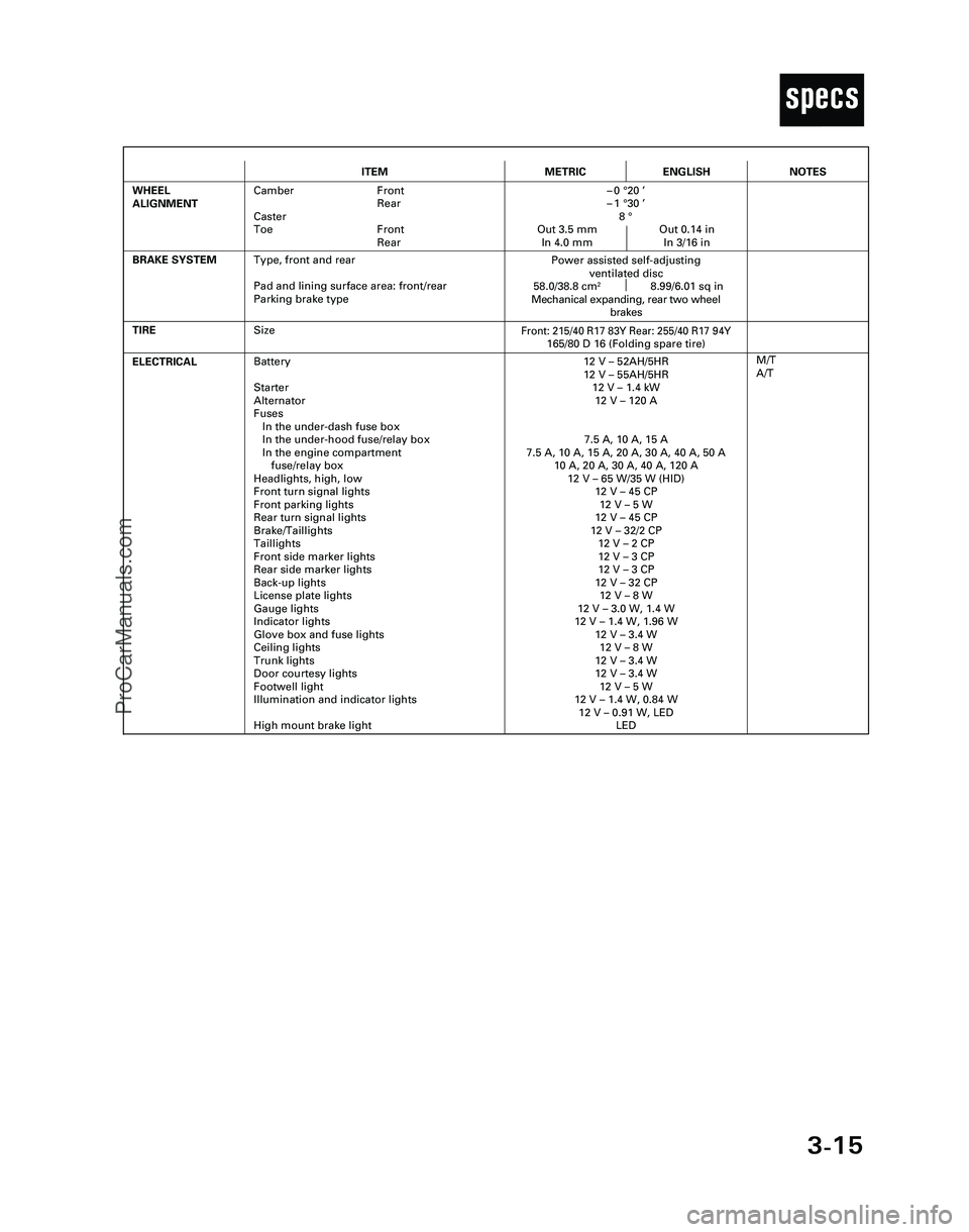
3-15
T
ITEMMETRICENGLISH
ELECTRICALBattery
Starter
Alternator
Fuses
In the under-dash fuse box
In the under-hood fuse/relay box
In the engine compartment
fuse/relay box
Headlights, high, low
Front turn signal lights
Front parking lights
Rear turn signal lights
Brake/Taillights
Taillights
Front side marker lights
Rear side marker lights
Back-up lights
License plate lights
Gauge lights
Indicator lights
Glove box and fuse lights
Ceiling lights
Trunk lights
Door courtesy lights
Footwell light
Illumination and indicator lights
High mount brake light12 V – 52AH/5HR
12 V – 55AH/5HR
12 V – 1.4 kW
12 V – 120 A
7.5 A, 10 A, 15 A
7.5 A, 10 A, 15 A, 20 A, 30 A, 40 A, 50 A
10 A, 20 A, 30 A, 40 A, 120 A
12 V – 65 W/35 W (HID)
12 V – 45 CP
12 V – 5 W
12 V – 45 CP
12 V – 32/2 CP
12 V – 2 CP
12 V – 3 CP
12 V – 3 CP
12 V – 32 CP
12 V – 8 W
12 V – 3.0 W, 1.4 W
12 V – 1.4 W, 1.96 W
12 V – 3.4 W
12 V – 8 W
12 V – 3.4 W
12 V – 3.4 W
12 V – 5 W
12 V – 1.4 W, 0.84 W
12 V – 0.91 W, LED
LED
TIRE
M/T
A/T
BRAKE SYSTEM
Front: 215/40 R17 83Y Rear: 255/40 R17 94Y165/80 D 16 (Folding spare tire)
Power assisted self-adjusting
ventilated disc
58.0/38.8 cm
28.99/6.01 sq in
Mechanical expanding, rear two wheel
brakes
WHEEL
ALIGNMENTCamber Front
Rear
Caster
Toe Front
Rear–0 °20 ’
–1 °30 ’
8 °
Out 3.5 mm Out 0.14 in
In 4.0 mm In 3/16 in
NOTES
Size
Type, front and rear
Pad and lining surface area: front/rear
Parking brake type
*04-NSX (61SW004)SEC03(01-16) 9/22/04 1:49 PM Page 3-15
ProCarManuals.com
Page 1060 of 1503
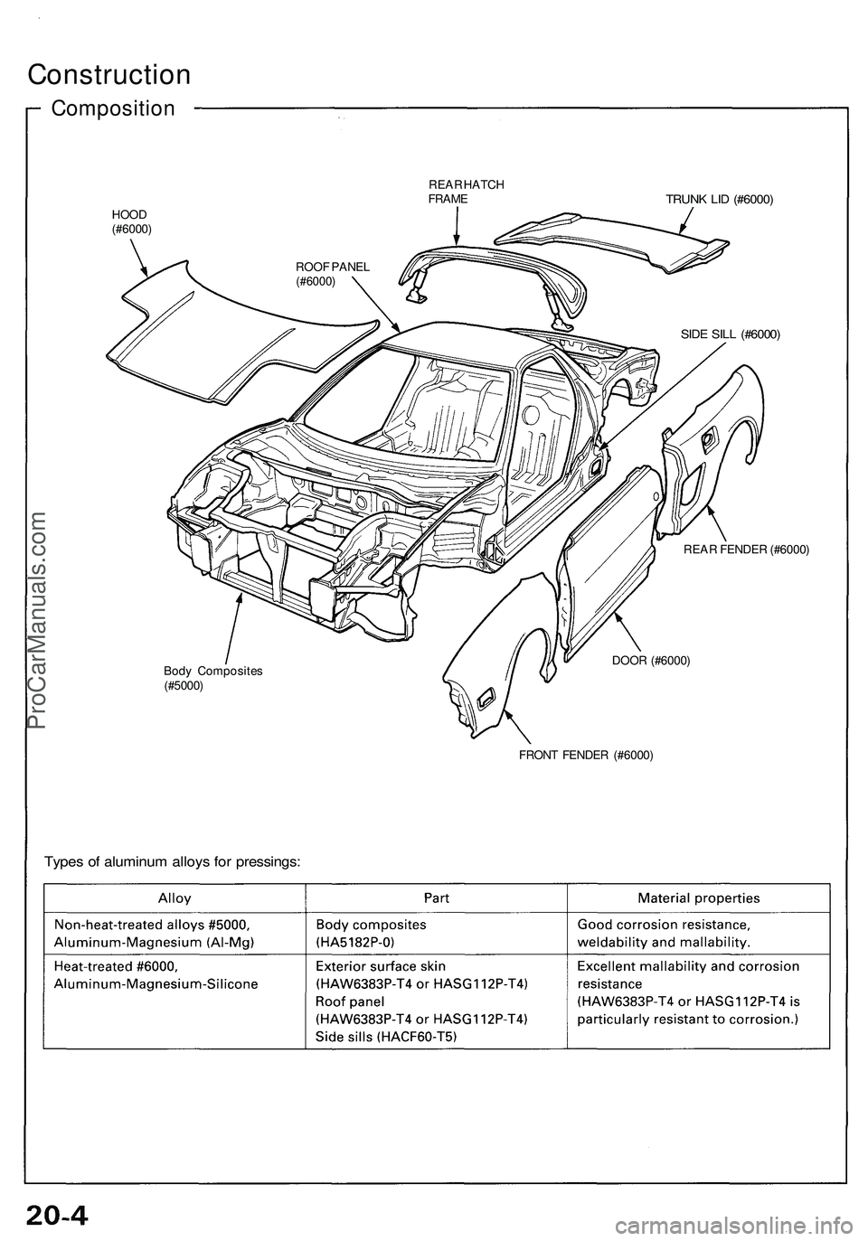
Construction
Composition
REAR HATCH
FRAME
TRUNK LID (#6000)
HOOD
(#6000)
SIDE SILL (#6000)
REAR FENDER (#6000)
Body Composites
(#5000)
DOOR (#6000)
FRONT FENDER (#6000)
Types of aluminum alloys for pressings:
ROOF PANEL
(#6000)ProCarManuals.com
Page 1064 of 1503
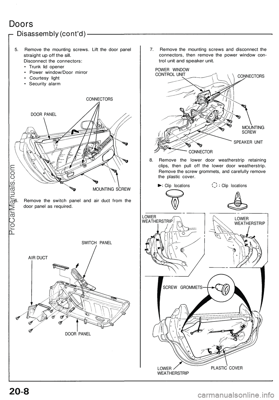
Doors
Disassembly (cont'd)
5. Remove the mounting screws. Lift the door panel
straight up off the sill.
Disconnect the connectors:
• Trunk lid opener
• Power window/Door mirror
• Courtesy light
• Security alarm
DOOR PANEL
CONNECTORS
MOUNTING SCREW
6. Remove the switch panel and air duct from the
door panel as required.
SWITCH PANEL
AIR DUCT
DOOR PANEL
7. Remove the mounting screws and disconnect the
connectors, then remove the power window con-
trol unit and speaker unit.
POWER WINDOW
CONTROL UNIT
CONNECTORS
MOUNTING
SCREW
SPEAKER UNIT
CONNECTOR
8. Remove the lower door weatherstrip retaining
clips, then pull off the lower door weatherstrip.
Remove the screw grommets, and carefully remove
the plastic cover.
Clip locations
Clip locations
LOWER
WEATHERSTRIP
PLASTIC COVER
LOWER
WEATHERSTRIP
LOWER
WEATHERSTRIP
SCREW GROMMETSProCarManuals.com
Page 1112 of 1503
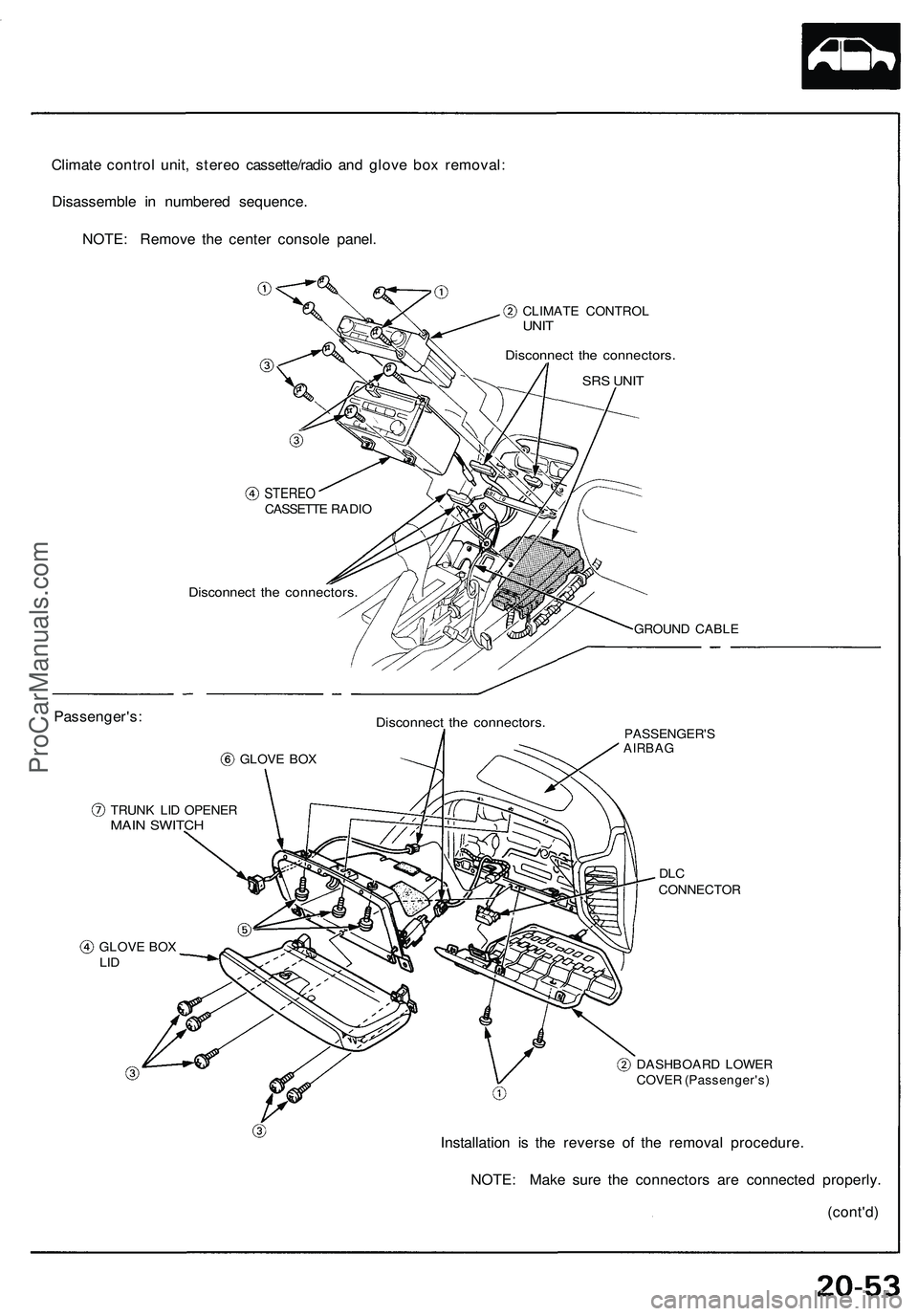
Climate control unit, stereo cassette/radio and glove box removal:
Disassemble in numbered sequence.
NOTE: Remove the center console panel.
CLIMATE CONTROL
UNIT
Disconnect the connectors.
SRS UNIT
Passenger's:
STEREO
CASSETTE RADIO
Disconnect the connectors.
GROUND CABLE
GLOVE BOX
Disconnect the connectors.
TRUNK LID OPENER
MAIN SWITCH
PASSENGER'S
AIRBAG
DLC
CONNECTOR
GLOVE BOX
LID
DASHBOARD LOWER
COVER (Passenger's)
Installation is the reverse of the removal procedure.
NOTE: Make sure the connectors are connected properly.
(cont'd)ProCarManuals.com
Page 1122 of 1503
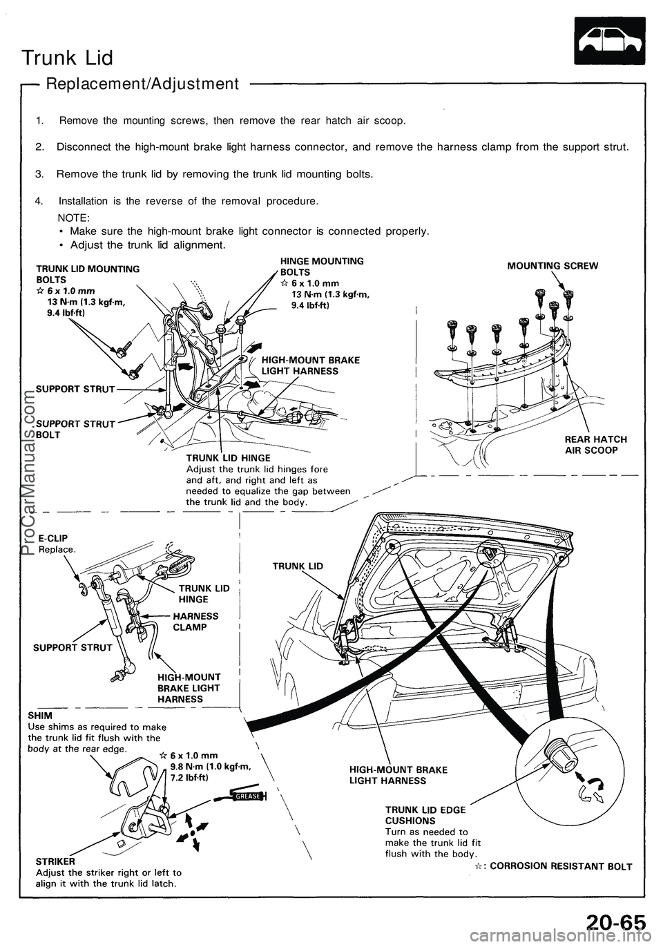
Trunk Lid
Replacement/Adjustment
1. Remove the mounting screws, then remove the rear hatch air scoop.
2. Disconnect the high-mount brake light harness connector, and remove the harness clamp from the support strut.
3. Remove the trunk lid by removing the trunk lid mounting bolts.
4. Installation is the reverse of the removal procedure.
NOTE:
• Make sure the high-mount brake light connector is connected properly.
• Adjust the trunk lid alignment.ProCarManuals.com
Page 1123 of 1503
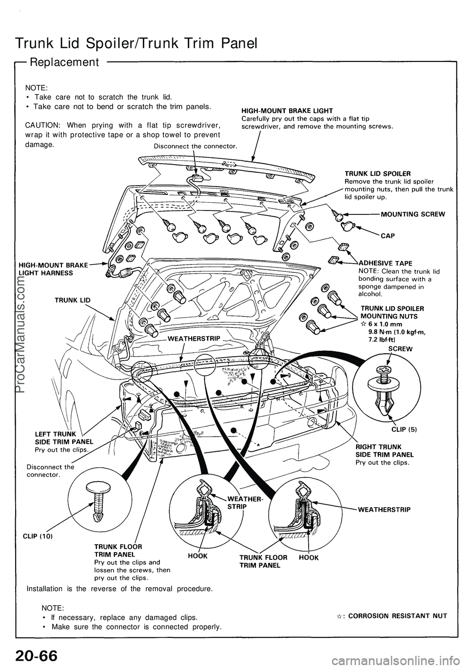
Trunk Lid Spoiler/Trunk Trim Panel
Replacement
NOTE:
• Take care not to scratch the trunk lid.
• Take care not to bend or scratch the trim panels.
CAUTION: When prying with a flat tip screwdriver,
wrap it with protective tape or a shop towel to prevent
damage.
Installation is the reverse of the removal procedure.
NOTE:
• If necessary, replace any damaged clips.
• Make sure the connector is connected properly.ProCarManuals.com