stop start ACURA RL KA9 1996 Service User Guide
[x] Cancel search | Manufacturer: ACURA, Model Year: 1996, Model line: RL KA9, Model: ACURA RL KA9 1996Pages: 1954, PDF Size: 61.44 MB
Page 1084 of 1954
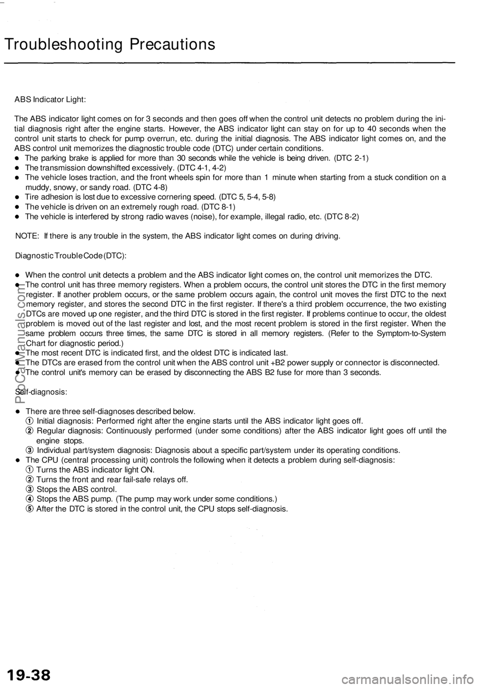
Troubleshooting Precautions
ABS Indicator Light:
The ABS indicator light comes on for 3 seconds and then goes off when the control unit detects no problem during the ini-
tial diagnosis right after the engine starts. However, the ABS indicator light can stay on for up to 40 seconds when the
control unit starts to check for pump overrun, etc. during the initial diagnosis. The ABS indicator light comes on, and the
ABS control unit memorizes the diagnostic trouble code (DTC) under certain conditions.
The parking brake is applied for more than 30 seconds while the vehicle is being driven. (DTC 2-1)
The transmission downshifted excessively. (DTC 4-1, 4-2)
The vehicle loses traction, and the front wheels spin for more than 1 minute when starting from a stuck condition on a
muddy, snowy, or sandy road. (DTC 4-8)
Tire adhesion is lost due to excessive cornering speed. (DTC 5, 5-4, 5-8)
The vehicle is driven on an extremely rough road. (DTC 8-1)
The vehicle is interfered by strong radio waves (noise), for example, illegal radio, etc. (DTC 8-2)
NOTE: If there is any trouble in the system, the ABS indicator light comes on during driving.
Diagnostic Trouble Code (DTC):
When the control unit detects a problem and the ABS indicator light comes on, the control unit memorizes the DTC.
The control unit has three memory registers. When a problem occurs, the control unit stores the DTC in the first memory
register. If another problem occurs, or the same problem occurs again, the control unit moves the first DTC to the next
memory register, and stores the second DTC in the first register. If there's a third problem occurrence, the two existing
DTCs are moved up one register, and the third DTC is stored in the first register. If problems continue to occur, the oldest
problem is moved out of the last register and lost, and the most recent problem is stored in the first register. When the
same problem occurs three times, the same DTC is stored in all memory registers. (Refer to the Symptom-to-System
Chart for diagnostic period.)
The most recent DTC is indicated first, and the oldest DTC is indicated last.
The DTCs are erased from the control unit when the ABS control unit +B2 power supply or connector is disconnected.
The control unit's memory can be erased by disconnecting the ABS B2 fuse for more than 3 seconds.
Self-diagnosis:
There are three self-diagnoses described below.
Initial diagnosis: Performed right after the engine starts until the ABS indicator light goes off.
Regular diagnosis: Continuously performed (under some conditions) after the ABS indicator light goes off until the
engine stops.
Individual part/system diagnosis: Diagnosis about a specific part/system under its operating conditions.
The CPU (central processing unit) controls the following when it detects a problem during self-diagnosis:
Turns the ABS indicator light ON.
Turns the front and rear fail-safe relays off.
Stops the ABS control.
Stops the ABS pump. (The pump may work under some conditions.)
After the DTC is stored in the control unit, the CPU stops self-diagnosis.ProCarManuals.com
Page 1104 of 1954
Troubleshooting
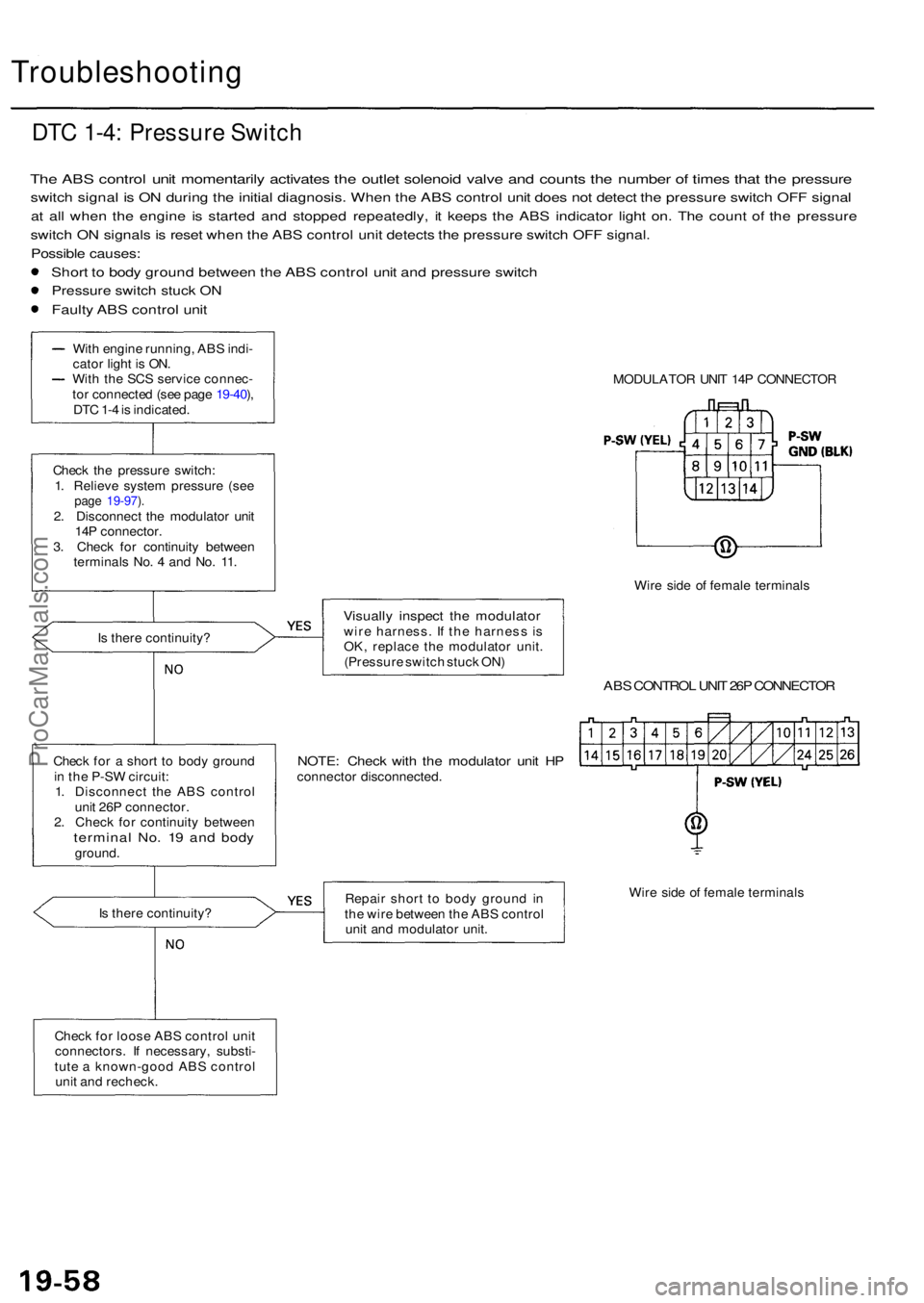
DTC 1-4 : Pressur e Switc h
The AB S contro l uni t momentaril y activate s th e outle t solenoi d valv e an d count s th e numbe r o f time s tha t th e pressur e
switch signa l i s O N durin g th e initia l diagnosis . Whe n th e AB S contro l uni t doe s no t detec t th e pressur e switc h OF F signa l
at al l whe n th e engin e i s starte d an d stoppe d repeatedly , i t keep s th e AB S indicato r ligh t on . Th e coun t o f th e pressur e
switch O N signal s i s rese t whe n th e AB S contro l uni t detect s th e pressur e switc h OF F signal .
Possibl e causes :
Short t o bod y groun d betwee n th e AB S contro l uni t an d pressur e switc h
Pressur e switc h stuc k O N
Fault y AB S contro l uni t
MODULATO R UNI T 14 P CONNECTO R
Wir e sid e o f femal e terminal s
Visually inspec t th e modulato rwire harness . I f th e harnes s i s
OK , replac e th e modulato r unit .
(Pressur e switc h stuc k ON )
ABS CONTRO L UNI T 26 P CONNECTO R
NOTE: Chec k wit h th e modulato r uni t H Pconnecto r disconnected .
Repai r shor t t o bod y groun d i n
th e wir e betwee n th e AB S contro l
uni t an d modulato r unit . Wir
e sid e o f femal e terminal s
Chec k fo r loos e AB S contro l uni t
connectors . I f necessary , substi -
tut e a known-goo d AB S contro l
uni t an d recheck .
I
s ther e continuity ?
Chec
k fo r a shor t t o bod y groun d
i n th e P-S W circuit :
1 . Disconnec t th e AB S contro l
uni t 26 P connector .
2 . Chec k fo r continuit y betwee n
termina l No . 1 9 an d bod yground .
Chec
k th e pressur e switch :
1 . Reliev e syste m pressur e (se e
page 19-97 ).2 . Disconnec t th e modulato r uni t
14 P connector .
3 . Chec k fo r continuit y betwee n
terminal s No . 4 an d No . 11 .
I s ther e continuity ?
Wit
h engin e running , AB S indi -
cato r ligh t i s ON .
Wit h th e SC S servic e connec -
to r connecte d (se e pag e 19-40 ),
DT C 1- 4 is indicated .
ProCarManuals.com
Page 1144 of 1954
Modulator Uni t
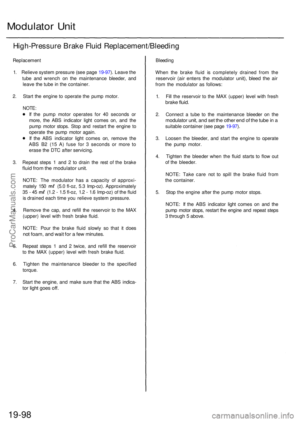
High-Pressur e Brak e Flui d Replacement/Bleedin g
Replacement
1. Reliev e syste m pressur e (se e pag e 19-97 ). Leav e th e
tub e an d wrenc h o n th e maintenanc e bleeder , an d
leav e th e tub e in th e container .
2 . Star t th e engin e t o operat e th e pum p motor .
NOTE:
If th e pum p moto r operate s fo r 4 0 second s o r
more , th e AB S indicato r ligh t come s on , an d th e
pum p moto r stops . Sto p an d restar t th e engin e t o
operat e th e pum p moto r again .
I f th e AB S indicator light come s on , remov e th e
AB S B 2 (1 5 A ) fus e fo r 3 second s o r mor e t o
eras e th e DT C afte r servicing .
3 . Repea t step s 1 an d 2 to drai n th e res t o f th e brak e
fluid fro m th e modulato r unit .
NOTE : Th e modulato r ha s a capacit y o f approxi -
mately 15 0 (5. 0 fl-oz , 5. 3 Imp-oz) . Approximatel y
35 - 4 5 (1. 2 - 1. 5 fl-oz , 1. 2 - 1. 6 Imp-oz ) o f th e flui d
i s draine d eac h tim e yo u reliev e syste m pressure .
4 . Remov e th e cap , an d refil l th e reservoi r t o th e MA X
(upper ) leve l wit h fres h brak e fluid .
NOTE : Pou r th e brak e flui d slowl y s o tha t i t doe s
not foam , an d wai t fo r a fe w minutes .
5. Repea t step s 1 an d 2 twice , an d refil l th e reservoi r
t o th e MA X (upper ) leve l wit h fres h brak e fluid .
6 . Tighte n th e maintenanc e bleede r t o th e specifie d
torque .
7 . Star t th e engine , an d mak e sur e tha t th e AB S indica -
tor ligh t goe s off .
Bleedin g
Whe n th e brak e flui d i s completel y draine d fro m th e
reservoi r (ai r enter s th e modulato r unit) , blee d th e ai r
from th e modulato r a s follows :
1 . Fil l th e reservoi r t o th e MA X (upper ) leve l wit h fres h
brake fluid .
2. Connec t a tub e t o th e maintenanc e bleede r o n th e
modulato r unit , an d se t th e othe r en d o f th e tub e in a
suitabl e containe r (se e pag e 19-97 ).
3 . Loose n th e bleeder , an d star t th e engin e t o operat e
th e pum p motor .
4 . Tighte n th e bleede r whe n th e flui d start s t o flo w ou t
o f th e bleeder .
NOTE : Tak e car e no t t o spil l th e brak e flui d fro m
th e container .
5 . Sto p th e engin e afte r th e pum p moto r stops .
NOTE : I f th e AB S indicato r ligh t come s o n an d th e
pum p moto r stops , restar t th e engin e an d repea t step s
3 throug h 5 above .
19-98ProCarManuals.com
Page 1152 of 1954
Anti-lock Brak e Syste m (ABS )
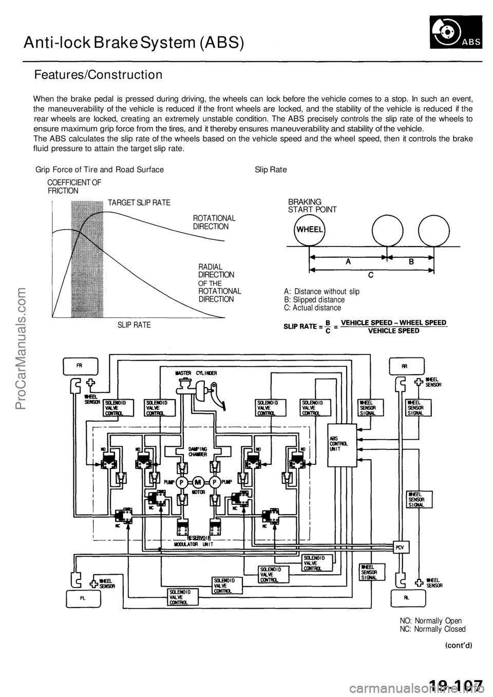
Features/Constructio n
When th e brak e peda l i s presse d durin g driving , th e wheel s ca n loc k befor e th e vehicl e come s t o a stop . I n suc h a n event ,
th e maneuverabilit y o f th e vehicl e i s reduce d i f th e fron t wheel s ar e locked , an d th e stabilit y o f th e vehicl e is reduce d if th e
rea r wheel s ar e locked , creatin g a n extremel y unstabl e condition . Th e AB S precisel y control s th e sli p rat e o f th e wheel s t o
ensur e maximu m gri p forc e fro m th e tires , an d it thereb y ensure s maneuverability and stabilit y o f th e vehicle .
The AB S calculate s th e sli p rat e o f th e wheel s base d o n th e vehicl e spee d an d th e whee l speed , the n it control s th e brak e
flui d pressur e to attai n th e targe t sli p rate .
Grip Forc e o f Tir e an d Roa d Surfac eSlip Rat e
COEFFICIEN T O F
FRICTIO N
TARGET SLI P RAT E
SLIP RAT E
ROTATIONA LDIRECTION
RADIALDIRECTIO NOF TH EROTATIONA L
DIRECTIO N
BRAKINGSTART POIN T
A: Distanc e withou t sli p
B : Slippe d distanc e
C : Actua l distanc e
NO: Normall y Ope n
NC : Normall y Close d
ProCarManuals.com
Page 1154 of 1954
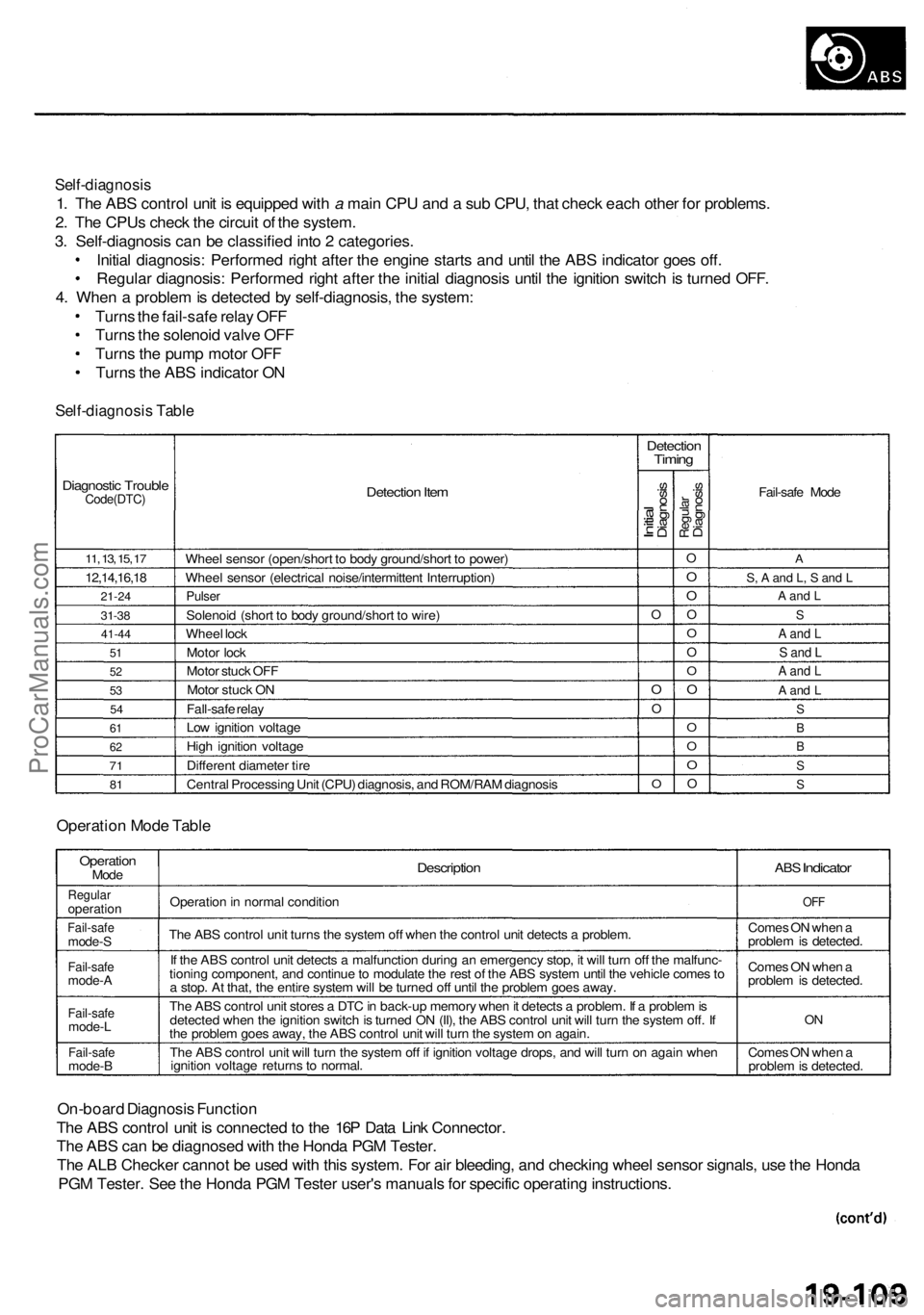
Self-diagnosis
1. The ABS control unit is equipped with a main CPU and a sub CPU, that check each other for problems.
2. The CPUs check the circuit of the system.
3. Self-diagnosis can be classified into 2 categories.
Initial diagnosis: Performed right after the engine starts and until the ABS indicator goes off.
Regular diagnosis: Performed right after the initial diagnosis until the ignition switch is turned OFF.
4. When a problem is detected by self-diagnosis, the system:
Turns the fail-safe relay OFF
Turns the solenoid valve OFF
Turns the pump motor OFF
Turns the ABS indicator ON
Self-diagnosis Table
Diagnostic Trouble
Code(DTC)
11, 13, 15, 17
12,14,16,18
21-24
31-38
41-44
51
52
53
54
61
62
71
81
Detection Item
Wheel sensor (open/short to body ground/short to power)
Wheel sensor (electrical noise/intermittent Interruption)
Pulser
Solenoid (short to body ground/short to wire)
Wheel lock
Motor lock
Motor stuck OFF
Motor stuck ON
Fall-safe relay
Low ignition voltage
High ignition voltage
Different diameter tire
Central Processing Unit (CPU) diagnosis, and ROM/RAM diagnosis
Detection
Timing
Initial
Diagnosis
O
O
O
O
Regular
Diagnosis
O
O
O
O
O
O
O
O
O
O
O
O
Fail-safe Mode
A
S, A and L, S and L
A and L
S
A and L
S and L
A and L
A and L
S
B
B
S
S
Operation Mode Table
Operation
Mode
Regular
operation
Fail-safe
mode-S
Fail-safe
mode-A
Fail-safe
mode-L
Fail-safe
mode-B
Description
Operation in normal condition
The ABS control unit turns the system off when the control unit detects a problem.
If the ABS control unit detects a malfunction during an emergency stop, it will turn off the malfunc-
tioning component, and continue to modulate the rest of the ABS system until the vehicle comes to
a stop. At that, the entire system will be turned off until the problem goes away.
The ABS control unit stores a DTC in back-up memory when it detects a problem. If a problem is
detected when the ignition switch is turned ON (II), the ABS control unit will turn the system off. If
the problem goes away, the ABS control unit will turn the system on again.
The ABS control unit will turn the system off if ignition voltage drops, and will turn on again when
ignition voltage returns to normal.
ABS
Indicator
OFF
Comes ON when a
problem is detected.
Comes ON when a
problem is detected.
ON
Comes ON when a
problem is detected.
On-board Diagnosis Function
The ABS control unit is connected to the 16P Data Link Connector.
The ABS can be diagnosed with the Honda PGM Tester.
The ALB Checker cannot be used with this system. For air bleeding, and checking wheel sensor signals, use the Honda
PGM Tester. See the Honda PGM Tester user's manuals for specific operating instructions.
ProCarManuals.com
Page 1155 of 1954
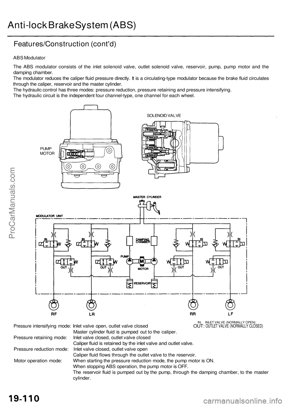
Anti-lock Brak e Syste m (ABS )
Features/Constructio n (cont'd )
ABS Modulato r
Th e AB S modulato r consist s of the inle t solenoi d valve , outle t solenoi d valve , reservoir , pump , pum p moto r an d th e
dampin g chamber .
The modulato r reduce s th e calipe r flui d pressur e directly . I t i s a circulating-typ e modulato r becaus e th e brak e flui d circulate s
throug h th e caliper , reservoi r an d th e maste r cylinder .
Th e hydrauli c contro l ha s thre e modes : pressur e reduction , pressur e retainin g an d pressur e intensifying .
Th e hydrauli c circui t i s th e independen t fou r channel-type , on e channe l fo r eac h wheel .
SOLENOI D VALV E
PUMPMOTO R
IN: INLE T VALV E (NORMALL Y OPEN )Pressur e intensifyin g mode : Inlet valv e open , outle t valv e close d OUT : OUTLET VALV E (NORMALL Y CLOSED )
Master cylinde r flui d is pumpe d ou t t o th e caliper .
Pressur e retainin g mode : Inle t valv e closed , outle t valv e close d
Caliper flui d is retaine d b y th e inle t valv e an d outle t valve .
Pressur e reductio n mode : Inle t valv e closed , outle t valv e ope n
Calipe r flui d flow s throug h th e outle t valv e to th e reservoir .
Whe n startin g th e pressur e reductio n mode , th e pum p moto r i s ON .
Whe n stoppin g AB S operation , th e pum p moto r i s OFF .
Th e reservoi r flui d is pumpe d ou t b y th e pump , throug h th e dampin g chamber , t o th e maste r
cylinder .
Moto
r operatio n mode :
ProCarManuals.com
Page 1196 of 1954

TCS CONTROL UNIT 20P CONNECTOR
Wire side of female terminals
VB: Battery Voltage
Terminal
number
1
2
4
5
6
9
10
11
12
13
14
15
16
17
20
Wire
color
BLK/YEL
GRN/RED
BLU
PNK/BLU
BLK/WHT
BLK
BRN/WHT
GRN/WHT
BLU
GRN/ORN
BLK/ORN
BRN/BLK
WHT/BLU
BLU/GRY
GRN
BRN
Terminal sign
(Terminal name)
IG1
(Ignition 1)
PARK
(Parking)
SCS
(Service check
signal)
STR-GND
(Steering ground)
AT-SHIFT
(AT shift)
FSR
(Fail-safe relay)
PMG
(Power motor
Ground)
VPM
(Voltage power
motor)
STOP
(Stop)
NEP (Engine
speed pulse)
BARO
(Barometric)
TC-FC
(Traction control
fuel cut)
LG2
(Logic ground 2)
STR-VCC (Steer-
ing power supply)
WARN2
(Warning 2)
SH-MOT
(Shield motor)
MOT +
(Motor +)
MOT-
(Motor -)
Description
Detects ignition switch
IG1 signal
Detects parking brake
switch signal
Detects service check
connector signal
(Diagnostic trouble
code indication)
Ground for the steering
angle sensor
Detects A/T shift posi-
tion signal
Drives fail-safe relay
Power ground for the
TCS control valve
actuator motor
Power source for the
TCS control valve
actuator motor
Detects brake pedal
position switch signal
Detects engine speed
signal
Detects barometric
sensor signal
TCS Fl, Fuel cut
(torque down) signal
Ground for the logic
circuit
Power source for the
steering angle sensor
Drives TCS indicator light
(The indicator light comes
on by the self-bias)
Shield for the TCS con-
trol valve actuator motor
Drives TCS control
valve actuator motor
Drives TCS control
valve actuator motor
Measurement
terminals
1-GND
2
3-GND
4-GND
5-GND
6-GND
9-GND
10-GND
11-GND
12-GND
13-GND
14-GND
15-GND
16-GND
17-GND
19-20
20-19
Voltage
Conditions
(Ignition Switch ON (II))
Depress the parking
brake pedal.
Release the parking
brake pedal.
SCS service connector
connected.
SCS service connector
disconnected.
Shift the transmission
to position, then
start the engine.
Start the engine.
Start the engine.
Brake pedal depressed.
Brake pedal released.
Engine idling
TCS is functioning,
(maximum fuel cut)
TCS is not functioning.
Indicator light ON
Indicator light OFF
TCS is functioning.
TCS is not functioning.
TCS is functioning.
TCS is not functioning.
Output
voltage
VB
Below 0.6 V
VB
0V
5V
Below 0.3V
About 4V
(5V 0V)
VB
1.5V
Below 0.3 V
0V
VB
VB
0V
About 6V
(12V
0V)
About 3 V
About 1.5V
About 4.5 V
(5 V,
PWM)
Below 0.3V
About 5 V
About 2 V
VB
VB
0V
VB
0VProCarManuals.com
Page 1306 of 1954
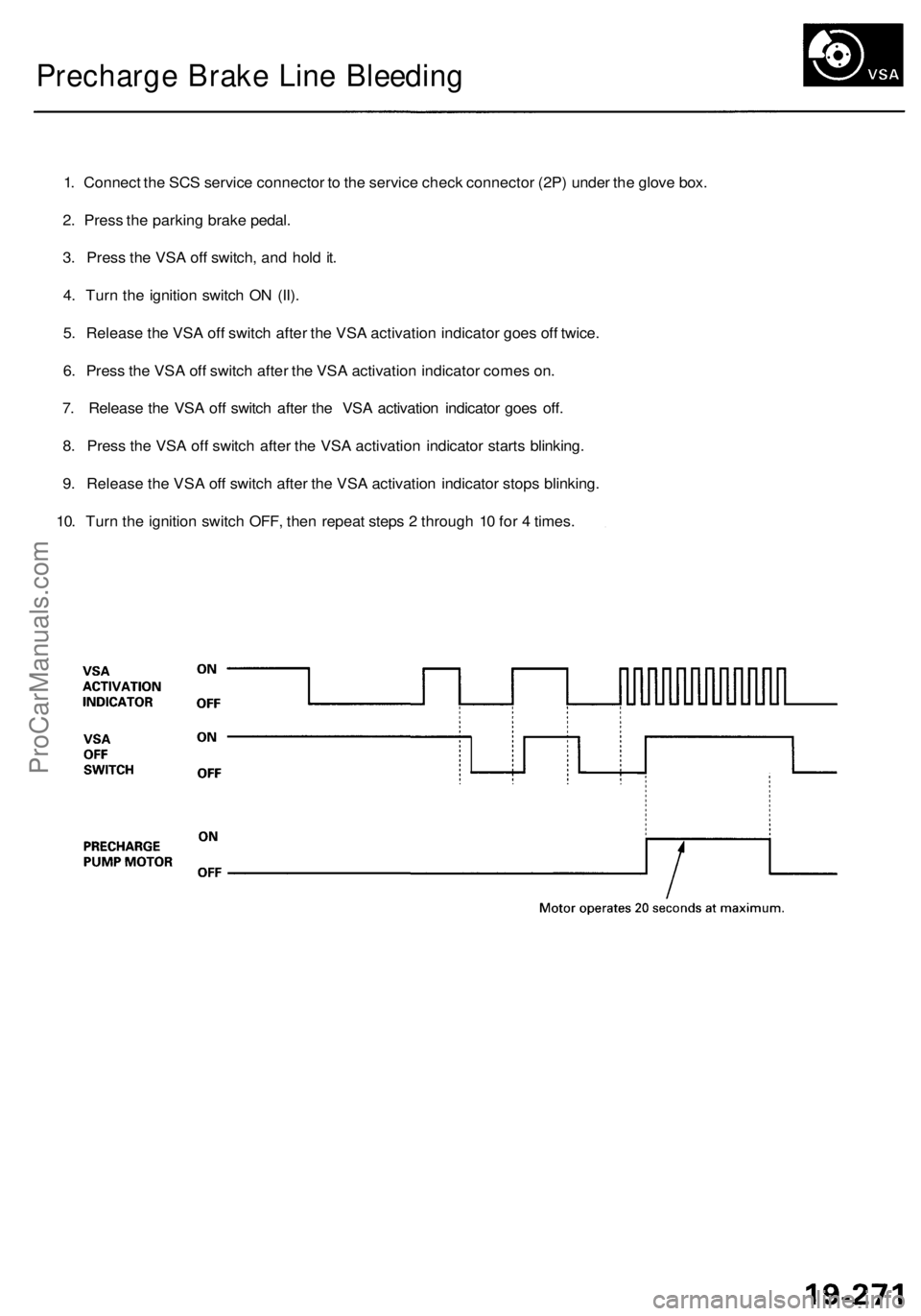
Precharge Brake Line Bleeding
1. Connect the SCS service connector to the service check connector (2P) under the glove box.
2. Press the parking brake pedal.
3. Press the VSA off switch, and hold it.
4. Turn the ignition switch ON (II).
5. Release the VSA off switch after the VSA activation indicator goes off twice.
6. Press the VSA off switch after the VSA activation indicator comes on.
7. Release the VSA off switch after the VSA activation indicator goes off.
8. Press the VSA off switch after the VSA activation indicator starts blinking.
9. Release the VSA off switch after the VSA activation indicator stops blinking.
10. Turn the ignition switch OFF, then repeat steps 2 through 10 for 4 times.ProCarManuals.com
Page 1580 of 1954
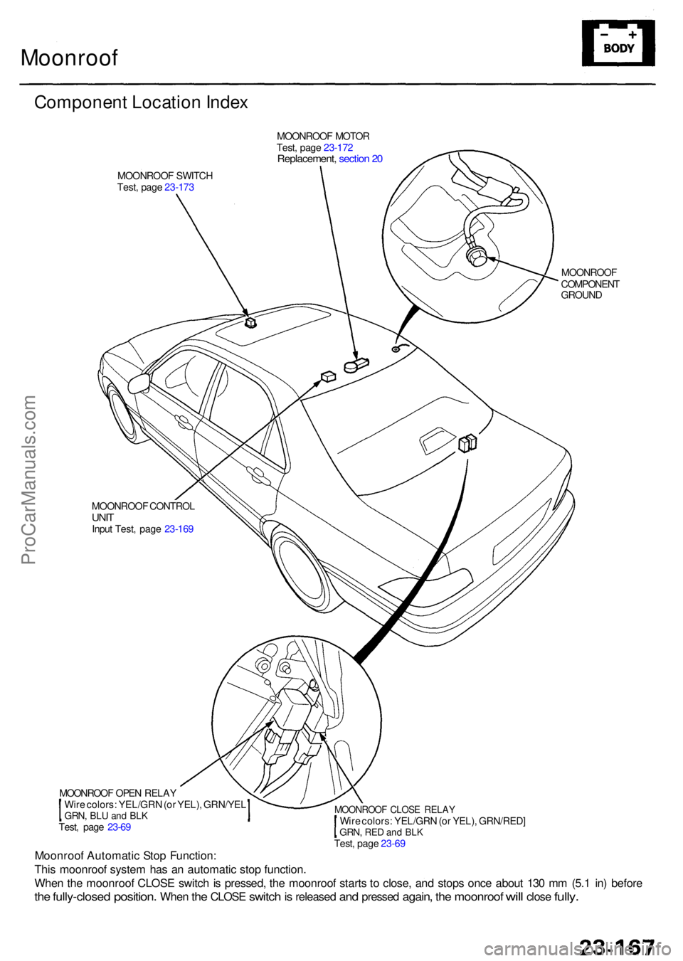
Moonroof
Componen t Locatio n Inde x
MOONROO F MOTO R
Test , pag e 23-17 2
Replacement , sectio n 2 0
MOONROO F SWITC H
Test , pag e 23-17 3
MOONROOF
COMPONEN T
GROUN D
MOONROO F CONTRO L
UNITInpu t Test , pag e 23-16 9
Moonroo f Automati c Sto p Function :
Thi s moonroo f syste m ha s a n automati c sto p function .
Whe n th e moonroo f CLOS E switc h is pressed , th e moonroo f start s t o close , an d stop s onc e abou t 13 0 m m (5. 1 in ) befor e
the fully-close d position. When the CLOS E switch is release d and presse d again, the moonroo f will clos e fully.
MOONROO F OPE N RELA Y
Wir e colors : YEL/GR N (o r YEL) , GRN/YE L
GRN, BLU an d BL KTest , pag e 23-6 9
MOONROO F CLOS E RELA YWire colors : YEL/GR N (o r YEL) , GRN/RED ]GRN, RED an d BL K Test , pag e 23-6 9
ProCarManuals.com
Page 1712 of 1954
![ACURA RL KA9 1996 Service User Guide From pag e 23-332
Indicato r flashe s
0.2 se c ON/2. 4 se c OF F(ARMED )
YES
Wan t th e syste m disarmed ?
• Trun k li d switc h O N
• Trun k ke y cylinde r switc h O N[UNLOCK ]
Trunk opene d wit ACURA RL KA9 1996 Service User Guide From pag e 23-332
Indicato r flashe s
0.2 se c ON/2. 4 se c OF F(ARMED )
YES
Wan t th e syste m disarmed ?
• Trun k li d switc h O N
• Trun k ke y cylinde r switc h O N[UNLOCK ]
Trunk opene d wit](/img/32/56992/w960_56992-1711.png)
From pag e 23-332
Indicato r flashe s
0.2 se c ON/2. 4 se c OF F(ARMED )
YES
Wan t th e syste m disarmed ?
• Trun k li d switc h O N
• Trun k ke y cylinde r switc h O N[UNLOCK ]
Trunk opene d wit h key ?YES
NO
N O
Illega l activit y (An y o f th e following )
1. Doo r i s opene d forcibl y o r
2 . Trun k li d is opene d withou t usin g th e ke y o r
3 . Hoo d is opene d o r
4 . Batter y terminal(s ) ar e disconnecte d an d
reconnecte d o r5. Engin e starte r circui t an d batter y circui t ar e
bypasse d b y breakin g th e ignitio n switc h o r
6 . Hood/trun k li d opene r i n th e vehicl e is
operate d o r
7. Pani c butto n is pushe d
• Th e horns , headlights , sid e marke r lights , an d tail -
light s soun d an d flas h repeatedl y fo r tw o minutes .
• Engin e starte r circui t interrupte d
Abou t 2 minute s passed ?
YESNOWan t th e syste m disarmed ?
YES
Eithe r doo r unlocke d b y usin g
th e ke y o r transmitte r
• Eithe r doo r ke y cylinde r switc h
ON [UNLOCK ]
The securit y alar m syste m isdisarme d
Indicato r stop s flashin g
Rear m th e securit y alar m system ?
NOYE S
To pag e 23-332
ProCarManuals.com