air bleeding ACURA RL KA9 1996 Service Repair Manual
[x] Cancel search | Manufacturer: ACURA, Model Year: 1996, Model line: RL KA9, Model: ACURA RL KA9 1996Pages: 1954, PDF Size: 61.44 MB
Page 422 of 1954
Hydraulic Tappets
Bleeding
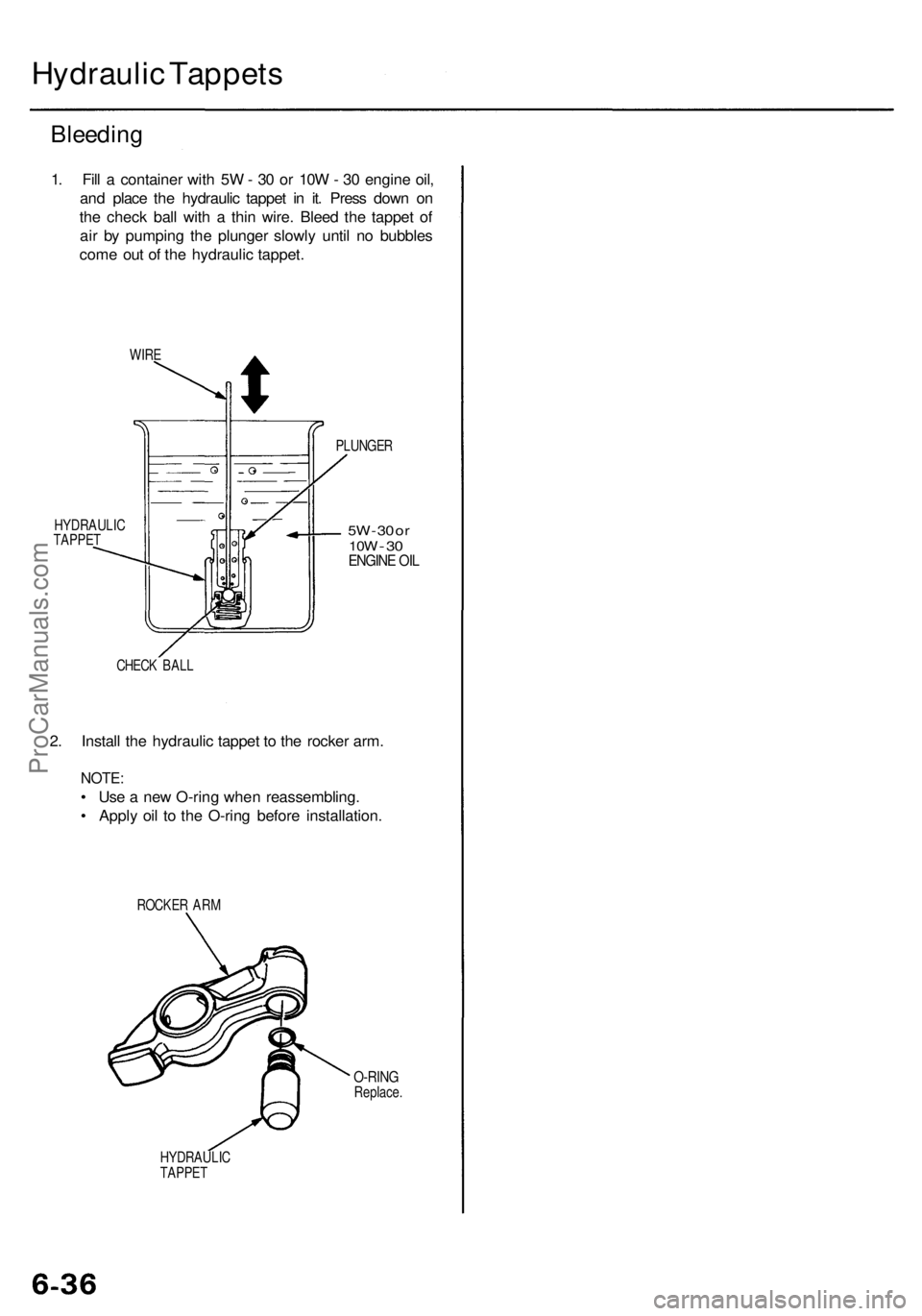
1. Fill a container with 5W - 30 or 10W - 30 engine oil,
and place the hydraulic tappet in it. Press down on
the check ball with a thin wire. Bleed the tappet of
air by pumping the plunger slowly until no bubbles
come out of the hydraulic tappet.
WIRE
HYDRAULIC
TAPPET
PLUNGER
5W
- 30 or
10W
-
30
ENGINE OIL
CHECK BALL
2. Install the hydraulic tappet to the rocker arm.
NOTE:
• Use a new O-ring when reassembling.
• Apply oil to the O-ring before installation.
ROCKER ARM
O-RING
Replace.
HYDRAULIC
TAPPETProCarManuals.com
Page 487 of 1954
Radiator
Illustrate d Inde x
Syste m is unde r hig h pressur e whe n th e
engin e i s hot . T o avoi d dange r o f releasin g scaldin g
coolant , remov e th e ca p onl y whe n th e engin e is cool .
Tota l Coolin g Syste m Capacit y (Includin g heate r an d
reservoir )
8.6 (9. 1 US qt , 7. 6 Im p qt )
Reservoi r capacity : 0.6 5 (0.6 9 U S qt , 0.5 7 Im p qt ) CAUTION
: Whe n pourin g engin e coolant , b e sur e t o
shu t th e rela y bo x li d an d no t t o spil l coolan t o n th e elec -
trica l part s o r th e painte d portion . I f an y coolan t spills ,
rins e it of f immediately .
NOTE:
Check al l coolin g syste m hose s fo r damage , leak s o r
deterioratio n an d replac e if necessary .
Chec k al l hos e clamp s an d retighte n i f necessary .
Us e ne w O-ring s whe n reassembling .
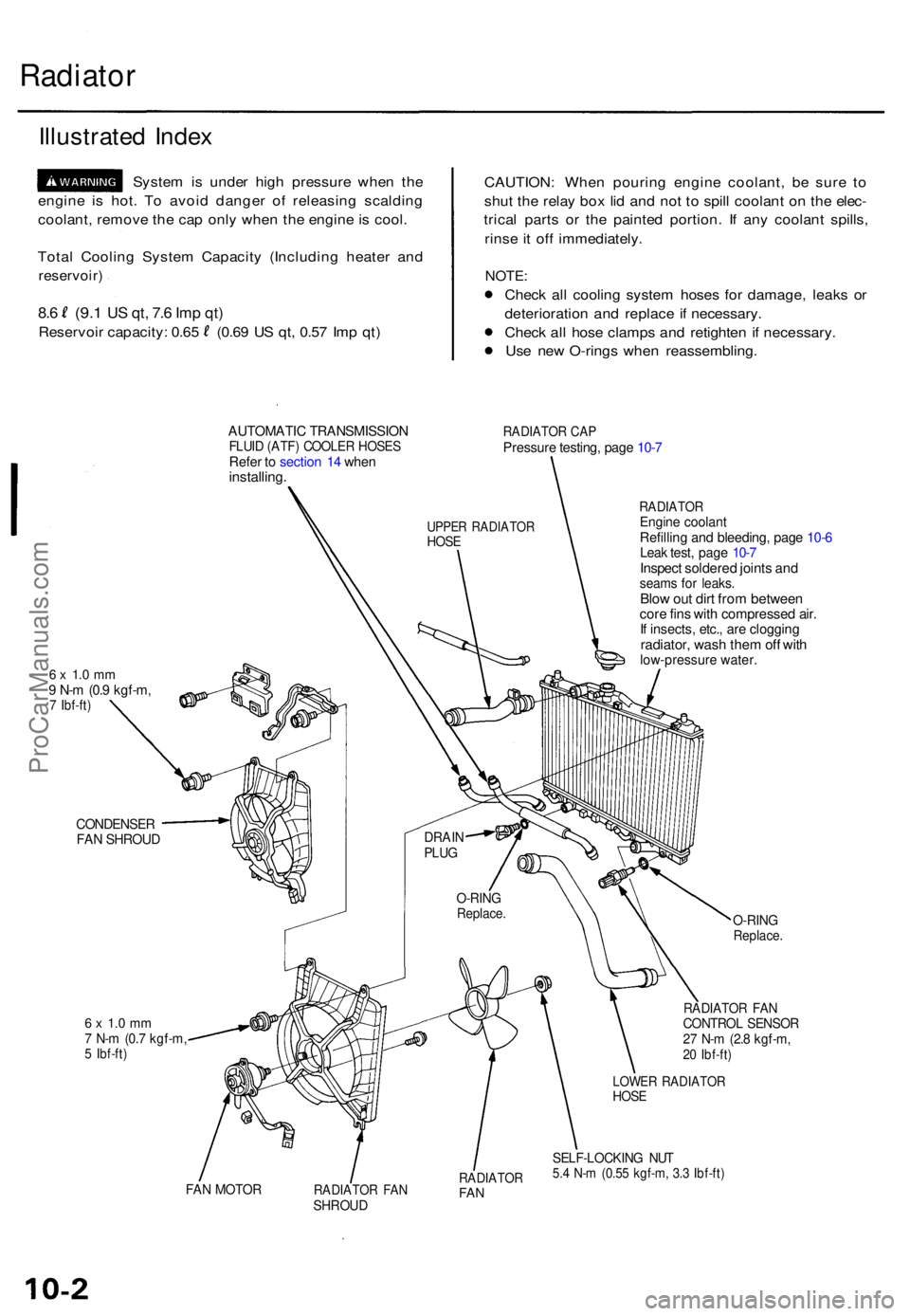
AUTOMATIC TRANSMISSIO NFLUID (ATF ) COOLE R HOSE SRefer t o sectio n 1 4 whe ninstalling .
RADIATO R CA PPressur e testing , pag e 10-7
6 x 1. 0 m m9 N- m (0. 9 kgf-m ,7 Ibf-ft )
RADIATO REngine coolan tRefilling an d bleeding , pag e 10-6Lea k test , pag e 10-7Inspec t soldere d joint s an dseam s fo r leaks .Blow ou t dir t fro m betwee ncore fin s wit h compresse d air .If insects , etc. , ar e cloggin gradiator, was h the m of f wit hlow-pressur e water .
CONDENSE RFAN SHROU D
6 x 1. 0 m m7 N- m (0. 7 kgf-m ,5 Ibf-ft )
O-RIN GReplace .
RADIATO R FA NCONTRO L SENSO R27 N- m (2. 8 kgf-m ,20 Ibf-ft )
FAN MOTO RRADIATO R FA NSHROU D
RADIATO RFAN
LOWE R RADIATO RHOSE
SELF-LOCKIN G NU T5.4 N- m (0.5 5 kgf-m , 3. 3 Ibf-ft )
O-RIN GReplace .
DRAINPLUG
UPPE R RADIATO RHOSE
ProCarManuals.com
Page 1054 of 1954
Inspection and Adjustment
Bleeding
CAUTION:
• Always use Genuine Honda DOT 3 Brake Fluid. Using
a non-Honda brake fluid can cause corrosion and
decrease the life of the system.
• Make sure no dirt or other foreign matter is allowed
to contaminate the brake fluid.
• Do not spill brake fluid on the vehicle, it may damage
the paint; if brake fluid does contact the paint, wash
it off immediately with water.
NOTE: The reservoir on the master cylinder must be at
the MAX (upper) level mark at the start of the bleeding
procedure and checked after bleeding each brake
caliper. Add fluid as required.
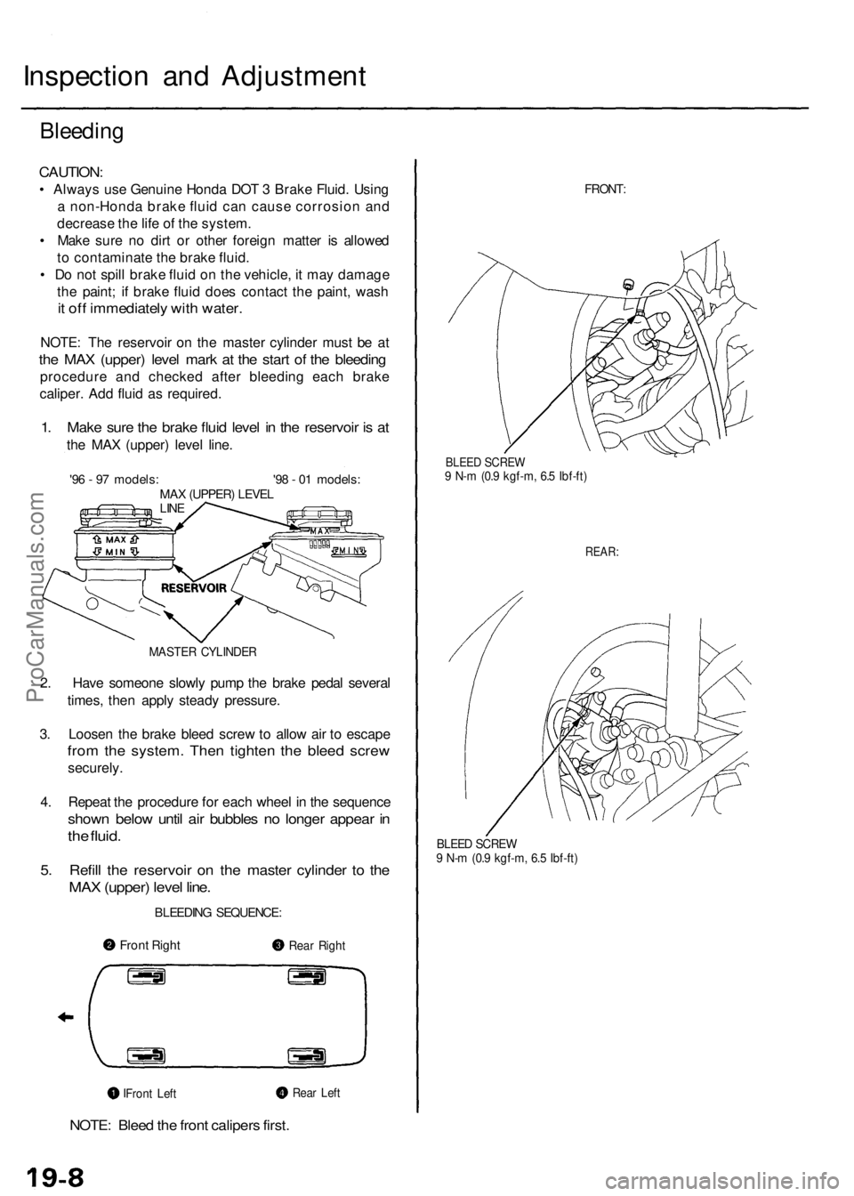
1. Make sure the brake fluid level in the reservoir is at
the MAX (upper) level line.
'96 - 97 models: '98 - 01 models:
MAX (UPPER) LEVEL
LINE
MASTER CYLINDER
2. Have someone slowly pump the brake pedal several
times, then apply steady pressure.
3. Loosen the brake bleed screw to allow air to escape
from the system. Then tighten the bleed screw
securely.
4. Repeat the procedure for each wheel in the sequence
shown below until air bubbles no longer appear in
the fluid.
5. Refill the reservoir on the master cylinder to the
MAX (upper) level line.
BLEEDING SEQUENCE:
NOTE: Bleed the front calipers first.
FRONT:
BLEED SCREW
9 N-m (0.9 kgf-m, 6.5 Ibf-ft)
REAR:
BLEED SCREW
9 N-m (0.9 kgf-m, 6.5 Ibf-ft)
Front Right
Rear Right
Rear Left
Front LeftProCarManuals.com
Page 1154 of 1954
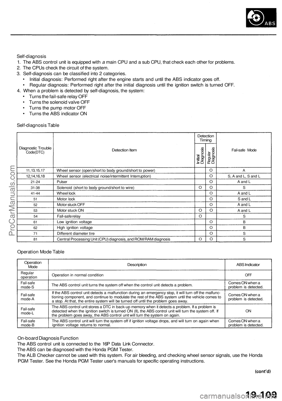
Self-diagnosis
1. The ABS control unit is equipped with a main CPU and a sub CPU, that check each other for problems.
2. The CPUs check the circuit of the system.
3. Self-diagnosis can be classified into 2 categories.
Initial diagnosis: Performed right after the engine starts and until the ABS indicator goes off.
Regular diagnosis: Performed right after the initial diagnosis until the ignition switch is turned OFF.
4. When a problem is detected by self-diagnosis, the system:
Turns the fail-safe relay OFF
Turns the solenoid valve OFF
Turns the pump motor OFF
Turns the ABS indicator ON
Self-diagnosis Table
Diagnostic Trouble
Code(DTC)
11, 13, 15, 17
12,14,16,18
21-24
31-38
41-44
51
52
53
54
61
62
71
81
Detection Item
Wheel sensor (open/short to body ground/short to power)
Wheel sensor (electrical noise/intermittent Interruption)
Pulser
Solenoid (short to body ground/short to wire)
Wheel lock
Motor lock
Motor stuck OFF
Motor stuck ON
Fall-safe relay
Low ignition voltage
High ignition voltage
Different diameter tire
Central Processing Unit (CPU) diagnosis, and ROM/RAM diagnosis
Detection
Timing
Initial
Diagnosis
O
O
O
O
Regular
Diagnosis
O
O
O
O
O
O
O
O
O
O
O
O
Fail-safe Mode
A
S, A and L, S and L
A and L
S
A and L
S and L
A and L
A and L
S
B
B
S
S
Operation Mode Table
Operation
Mode
Regular
operation
Fail-safe
mode-S
Fail-safe
mode-A
Fail-safe
mode-L
Fail-safe
mode-B
Description
Operation in normal condition
The ABS control unit turns the system off when the control unit detects a problem.
If the ABS control unit detects a malfunction during an emergency stop, it will turn off the malfunc-
tioning component, and continue to modulate the rest of the ABS system until the vehicle comes to
a stop. At that, the entire system will be turned off until the problem goes away.
The ABS control unit stores a DTC in back-up memory when it detects a problem. If a problem is
detected when the ignition switch is turned ON (II), the ABS control unit will turn the system off. If
the problem goes away, the ABS control unit will turn the system on again.
The ABS control unit will turn the system off if ignition voltage drops, and will turn on again when
ignition voltage returns to normal.
ABS
Indicator
OFF
Comes ON when a
problem is detected.
Comes ON when a
problem is detected.
ON
Comes ON when a
problem is detected.
On-board Diagnosis Function
The ABS control unit is connected to the 16P Data Link Connector.
The ABS can be diagnosed with the Honda PGM Tester.
The ALB Checker cannot be used with this system. For air bleeding, and checking wheel sensor signals, use the Honda
PGM Tester. See the Honda PGM Tester user's manuals for specific operating instructions.
ProCarManuals.com
Page 1161 of 1954
Troubleshooting Precautions
Kickback
1. The motor operates when the ABS is functioning, and the fluid in the reservoir is forced out to the master cylinder,
causing kickback at the brake pedal.
Pump Motor
1. The pump motor operates when the ABS is functioning.
2. The ABS control unit checks the pump motor operation during initial diagnosis when the vehicle is started. You may
hear the motor operate at this time, but it is normal.
Brake Fluid Replacement/Air Bleeding
1. Brake fluid replacement and air bleeding procedures are the same as vehicles without ABS. To ease bleeding, start
with the front wheels.
Troubleshooting
1. The troubleshooting flowcharts procedures assume that the cause of the problem is still present and the ABS indicator
is still on. Following the flowchart when the ABS indicator does not come on can result in incorrect diagnosis.
2. Question the customer about the conditions when the problem occurred, and try to reproduce the same conditions
for troubleshooting.
Find out when the ABS indicator came on, such as during initial diagnosis, during ABS control, after ABS control,
when vehicle speed was at a certain speed, etc.
3. When the ABS indicator does not come on during the test-drive, but troubleshooting is performed based on the DTC,
check for loose connectors, poor contact at the terminals, etc. before you start troubleshooting.
4. After troubleshooting, erase the DTC and test-drive the vehicle. Be sure the ABS indicator does not come on.
5. The connector illustrations show the female terminals with a single outline and the male terminals with a double outline.ProCarManuals.com