brake fluid ACURA RL KA9 1996 Service Repair Manual
[x] Cancel search | Manufacturer: ACURA, Model Year: 1996, Model line: RL KA9, Model: ACURA RL KA9 1996Pages: 1954, PDF Size: 61.44 MB
Page 309 of 1954
Lubrication Points
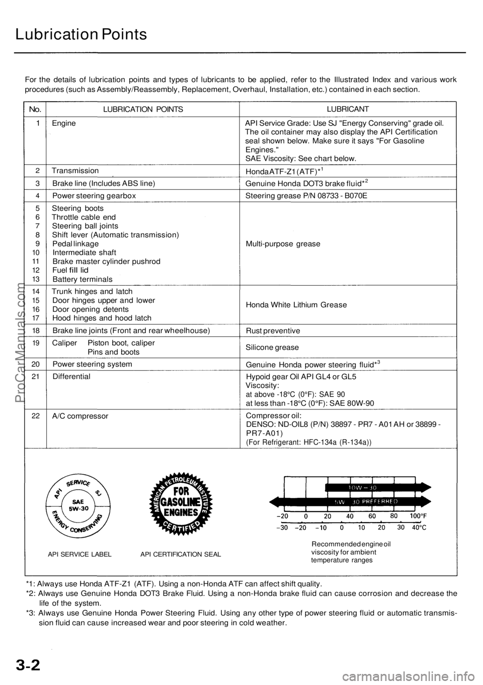
For the details of lubrication points and types of lubricants to be applied, refer to the Illustrated Index and various work
procedures (such as Assembly/Reassembly, Replacement, Overhaul, Installation, etc.) contained in each section.
No.
1
2
3
4
5
6
7
8
9
10
11
12
13
14
15
16
17
18
19
20
21
22
LUBRICATION POINTS
Engine
Transmission
Brake line (Includes ABS line)
Power steering gearbox
Steering boots
Throttle cable end
Steering ball joints
Shift lever (Automatic transmission)
Pedal linkage
Intermediate shaft
Brake master cylinder pushrod
Fuel
fill
lid
Battery terminals
Trunk hinges and latch
Door hinges upper and lower
Door opening detents
Hood hinges and hood latch
Brake line joints (Front and rear wheelhouse)
Caliper Piston boot, caliper
Pins and boots
Power steering system
Differential
A/C compressor
API SERVICE LABEL API CERTIFICATION SEAL
LUBRICANT
API Service Grade: Use SJ "Energy Conserving" grade oil.
The oil container may also display the API Certification
seal shown below. Make sure it says "For Gasoline
Engines."
SAE Viscosity: See chart below.
Honda ATF-Z1 (ATF)*1
Genuine Honda DOT3 brake fluid*2
Steering grease P/N 08733 - B070E
Multi-purpose grease
Honda White Lithium Grease
Rust preventive
Silicone grease
Genuine Honda power steering fluid*3
Hypoid gear Oil API GL4 or GL5
Viscosity:
at above -18°C (0°F): SAE 90
at less than -18°C (0°F): SAE 80W-90
Compressor oil:
DENSO: ND-OIL8 (P/N) 38897 - PR7 - A01 AH or 38899 -
PR7-A01)
(For Refrigerant: HFC-134a (R-134a))
Recommended engine oil
viscosity for ambient
temperature ranges
*1: Always use Honda ATF-Z1 (ATF). Using a non-Honda ATF can affect shift quality.
*2: Always use Genuine Honda DOT3 Brake Fluid. Using a non-Honda brake fluid can cause corrosion and decrease the
life of the system.
*3: Always use Genuine Honda Power Steering Fluid. Using any other type of power steering fluid or automatic transmis-
sion fluid can cause increased wear and poor steering in cold weather.ProCarManuals.com
Page 1050 of 1954
Inspection
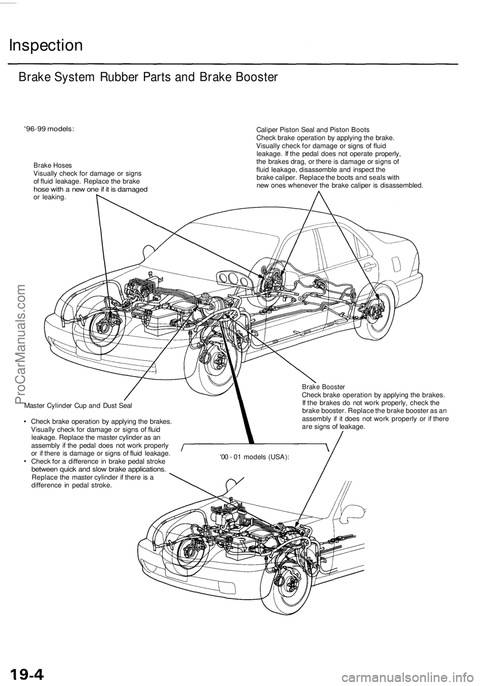
'96-99 models:
Brake Hoses
Visually check for damage or signs
of fluid leakage. Replace the brake
hose with a new one if it is damaged
or leaking.
Caliper Piston Seal and Piston Boots
Check brake operation by applying the brake.
Visually check for damage or signs of fluid
leakage. If the pedal does not operate properly,
the brakes drag, or there is damage or signs of
fluid leakage, disassemble and inspect the
brake caliper. Replace the boots and seals with
new ones whenever the brake caliper is disassembled.
Master Cylinder Cup and Dust Seal
Check brake operation by applying the brakes.
Visually check for damage or signs of fluid
leakage. Replace the master cylinder as an
assembly if the pedal does not work properly
or if there is damage or signs of fluid leakage.
Check for a difference in brake pedal stroke
between quick and slow brake applications.
Replace the master cylinder if there is a
difference in pedal stroke.
Brake Booster
Check brake operation by applying the brakes.
If the brakes do not work properly, check the
brake booster. Replace the brake booster as an
assembly if it does not work properly or if there
are signs of leakage.
Brake System Rubber Parts and Brake Booster
'00 - 01 models (USA):ProCarManuals.com
Page 1054 of 1954
Inspection and Adjustment
Bleeding
CAUTION:
• Always use Genuine Honda DOT 3 Brake Fluid. Using
a non-Honda brake fluid can cause corrosion and
decrease the life of the system.
• Make sure no dirt or other foreign matter is allowed
to contaminate the brake fluid.
• Do not spill brake fluid on the vehicle, it may damage
the paint; if brake fluid does contact the paint, wash
it off immediately with water.
NOTE: The reservoir on the master cylinder must be at
the MAX (upper) level mark at the start of the bleeding
procedure and checked after bleeding each brake
caliper. Add fluid as required.
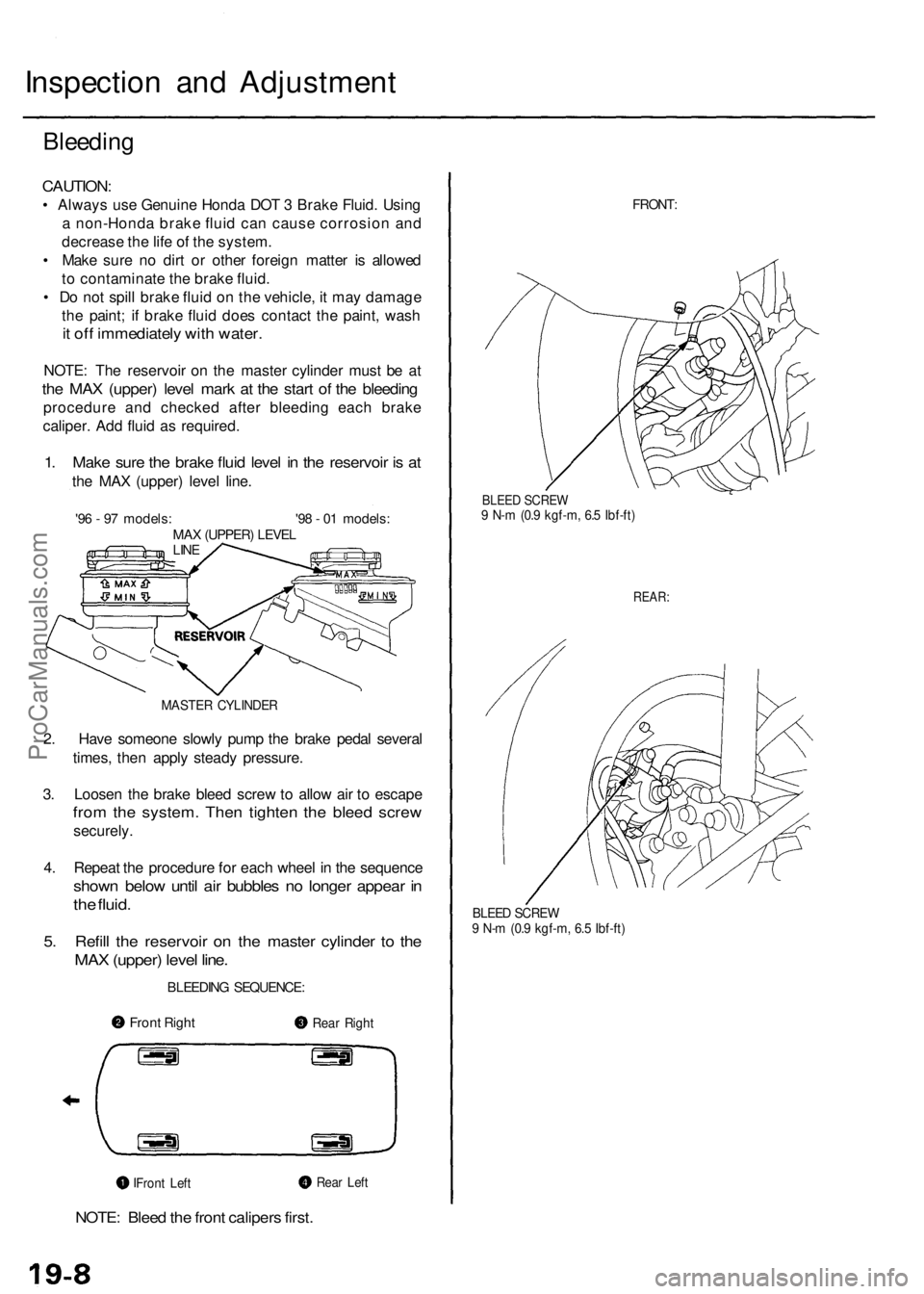
1. Make sure the brake fluid level in the reservoir is at
the MAX (upper) level line.
'96 - 97 models: '98 - 01 models:
MAX (UPPER) LEVEL
LINE
MASTER CYLINDER
2. Have someone slowly pump the brake pedal several
times, then apply steady pressure.
3. Loosen the brake bleed screw to allow air to escape
from the system. Then tighten the bleed screw
securely.
4. Repeat the procedure for each wheel in the sequence
shown below until air bubbles no longer appear in
the fluid.
5. Refill the reservoir on the master cylinder to the
MAX (upper) level line.
BLEEDING SEQUENCE:
NOTE: Bleed the front calipers first.
FRONT:
BLEED SCREW
9 N-m (0.9 kgf-m, 6.5 Ibf-ft)
REAR:
BLEED SCREW
9 N-m (0.9 kgf-m, 6.5 Ibf-ft)
Front Right
Rear Right
Rear Left
Front LeftProCarManuals.com
Page 1059 of 1954
Front Brake Caliper
Disassembly/Reassembly
Never use an air hose or dry brush to clean brake assemblies.
Use an OSHA-approved vacuum cleaner to avoid breathing brake dust.
Contaminated brake discs or pads reduce stopping ability.
When reusing the pads, always reinstall the brake pads in their original positions to prevent loss of braking efficiency.
CAUTION:
Do not spill brake fluid on the vehicle; it may damage the paint; if brake fluid does contact the paint, wash it off imme-
diately with water.
To prevent spills, cover the hose joints with rags or shop towels.
Clean all parts in brake fluid and air dry; blow out all passages with compressed air.
Before reassembling, check that all parts are free of dust and other foreign particles.
Replace parts with new ones whenever specified to do so.
Make sure no dirt or other foreign matter is allowed to contaminate the brake fluid.
Always use Genuine Honda DOT 3 Brake Fluid. Using a non-Honda brake fluid can cause corrosion and decrease the
life of the system.
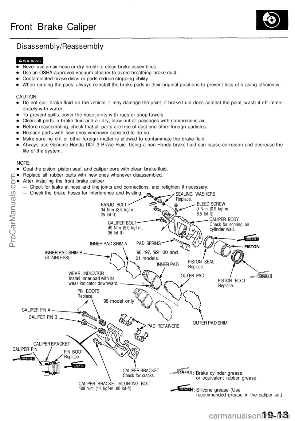
INNER PAD SHIM A
INNER PAD SHIM B
(STAINLESS)
'96, '97, '99,
'00 and
01 models:
INNER PAD
WEAR INDICATOR
Install inner pad with its
wear indicator downward.
PISTON SEAL
Replace.
OUTER PAD
PIN BOOTS
Replace.
'98 model only
CALIPER PIN A
CALIPER PIN B
CALIPER BRACKET
CALIPER PIN
PIN BOOT
Replace.
PISTON BOOT
Replace.
PAD RETAINERS
OUTER PAD SHIM
CALIPER BRACKET
Check for cracks.
CALIPER BRACKET MOUNTING BOLT
108 N-m (11 kgf-m, 80 Ibf-ft)
Brake cylinder grease
or equivalent rubber grease.
Silicone grease (Use
recommended grease in the caliper set).
NOTE:
Coat the piston, piston seal, and caliper bore with clean brake fluid.
Replace all rubber parts with new ones whenever disassembled.
After installing the front brake caliper:
— Check for leaks at hose and line joints and connections, and retighten if necessary.
— Check the brake hoses for interference and twisting.
BANJO BOLT
34 N-m (3.5 kgf-m,
25 Ibf-ft)
CALIPER BOLT
49 N-m (5.0 kgf-m,
36 Ibf-ft)
SEALING WASHERS
Replace.
BLEED SCREW
9 N-m (0.9 kgf-m,
6.5 Ibf-ft)
CALIPER BODY
Check for scoring on
cylinder wall.
PAD SPRINGProCarManuals.com
Page 1061 of 1954
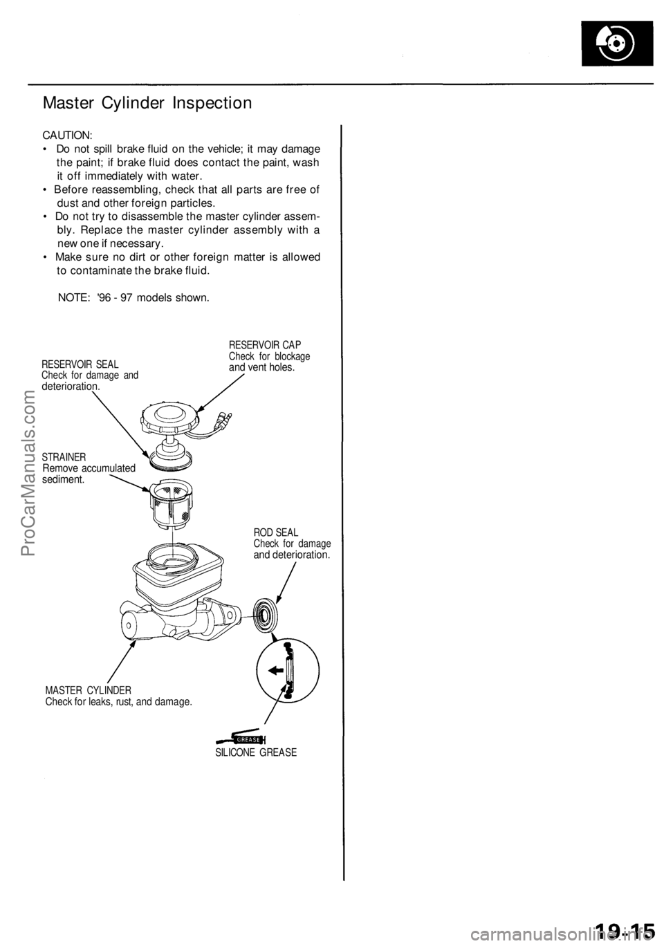
Master Cylinder Inspection
CAUTION:
• Do not spill brake fluid on the vehicle; it may damage
the paint; if brake fluid does contact the paint, wash
it off immediately with water.
• Before reassembling, check that all parts are free of
dust and other foreign particles.
• Do not try to disassemble the master cylinder assem-
bly. Replace the master cylinder assembly with a
new one if necessary.
• Make sure no dirt or other foreign matter is allowed
to contaminate the brake fluid.
NOTE: '96 - 97 models shown.
RESERVOIR SEAL
Check for damage and
deterioration.
RESERVOIR CAP
Check for blockage
and vent holes.
STRAINER
Remove accumulated
sediment.
ROD SEAL
Check for damage
and deterioration.
MASTER CYLINDER
Check for leaks, rust, and damage.
SILICONE GREASEProCarManuals.com
Page 1068 of 1954
Rear Brake Caliper
Disassembly/Reassembly
Never use an air hose or dry brush to clean brake assemblies.
Use an OSHA-approved vacuum cleaner to avoid breathing brake dust.
Contaminated brake discs or pads reduce stopping ability.
When reusing the pads, always reinstall the brake pads in their original positions to prevent loss of braking efficiency.
CAUTION:
Do not spill brake fluid on the vehicle; it may damage the paint; if brake fluid does contact the paint, wash it off imme-
diately with water.
To prevent spills, cover the hose joints with rags or shop towels.
Clean all parts in brake fluid and air dry; blow out all passages with compressed air.
Before reassembling, check that all parts are free of dust and other foreign particles.
Replace parts with new ones whenever specified to do so.
Make sure no dirt or other foreign matter is allowed to contaminate the brake fluid.
Always use Genuine Honda DOT 3 Brake Fluid. Using a non-Honda brake fluid can cause corrosion and decrease the
life of the system.
NOTE:
Coat the piston, piston seal, and caliper bore with clean brake fluid.
Replace all rubber parts with new ones whenever disassembled.
After installing the rear brake caliper:
— Check for leaks at hose and line joints and connections, and retighten if necessary.
— Check the brake hoses for interference and twisting.ProCarManuals.com
Page 1144 of 1954
Modulator Uni t
High-Pressur e Brak e Flui d Replacement/Bleedin g
Replacement
1. Reliev e syste m pressur e (se e pag e 19-97 ). Leav e th e
tub e an d wrenc h o n th e maintenanc e bleeder , an d
leav e th e tub e in th e container .
2 . Star t th e engin e t o operat e th e pum p motor .
NOTE:
If th e pum p moto r operate s fo r 4 0 second s o r
more , th e AB S indicato r ligh t come s on , an d th e
pum p moto r stops . Sto p an d restar t th e engin e t o
operat e th e pum p moto r again .
I f th e AB S indicator light come s on , remov e th e
AB S B 2 (1 5 A ) fus e fo r 3 second s o r mor e t o
eras e th e DT C afte r servicing .
3 . Repea t step s 1 an d 2 to drai n th e res t o f th e brak e
fluid fro m th e modulato r unit .
NOTE : Th e modulato r ha s a capacit y o f approxi -
mately 15 0 (5. 0 fl-oz , 5. 3 Imp-oz) . Approximatel y
35 - 4 5 (1. 2 - 1. 5 fl-oz , 1. 2 - 1. 6 Imp-oz ) o f th e flui d
i s draine d eac h tim e yo u reliev e syste m pressure .
4 . Remov e th e cap , an d refil l th e reservoi r t o th e MA X
(upper ) leve l wit h fres h brak e fluid .
NOTE : Pou r th e brak e flui d slowl y s o tha t i t doe s
not foam , an d wai t fo r a fe w minutes .
5. Repea t step s 1 an d 2 twice , an d refil l th e reservoi r
t o th e MA X (upper ) leve l wit h fres h brak e fluid .
6 . Tighte n th e maintenanc e bleede r t o th e specifie d
torque .
7 . Star t th e engine , an d mak e sur e tha t th e AB S indica -
tor ligh t goe s off .
Bleedin g
Whe n th e brak e flui d i s completel y draine d fro m th e
reservoi r (ai r enter s th e modulato r unit) , blee d th e ai r
from th e modulato r a s follows :
1 . Fil l th e reservoi r t o th e MA X (upper ) leve l wit h fres h
brake fluid .
2. Connec t a tub e t o th e maintenanc e bleede r o n th e
modulato r unit , an d se t th e othe r en d o f th e tub e in a
suitabl e containe r (se e pag e 19-97 ).
3 . Loose n th e bleeder , an d star t th e engin e t o operat e
th e pum p motor .
4 . Tighte n th e bleede r whe n th e flui d start s t o flo w ou t
o f th e bleeder .
NOTE : Tak e car e no t t o spil l th e brak e flui d fro m
th e container .
5 . Sto p th e engin e afte r th e pum p moto r stops .
NOTE : I f th e AB S indicato r ligh t come s o n an d th e
pum p moto r stops , restar t th e engin e an d repea t step s
3 throug h 5 above .
19-98ProCarManuals.com
Page 1161 of 1954
Troubleshooting Precautions
Kickback
1. The motor operates when the ABS is functioning, and the fluid in the reservoir is forced out to the master cylinder,
causing kickback at the brake pedal.
Pump Motor
1. The pump motor operates when the ABS is functioning.
2. The ABS control unit checks the pump motor operation during initial diagnosis when the vehicle is started. You may
hear the motor operate at this time, but it is normal.
Brake Fluid Replacement/Air Bleeding
1. Brake fluid replacement and air bleeding procedures are the same as vehicles without ABS. To ease bleeding, start
with the front wheels.
Troubleshooting
1. The troubleshooting flowcharts procedures assume that the cause of the problem is still present and the ABS indicator
is still on. Following the flowchart when the ABS indicator does not come on can result in incorrect diagnosis.
2. Question the customer about the conditions when the problem occurred, and try to reproduce the same conditions
for troubleshooting.
Find out when the ABS indicator came on, such as during initial diagnosis, during ABS control, after ABS control,
when vehicle speed was at a certain speed, etc.
3. When the ABS indicator does not come on during the test-drive, but troubleshooting is performed based on the DTC,
check for loose connectors, poor contact at the terminals, etc. before you start troubleshooting.
4. After troubleshooting, erase the DTC and test-drive the vehicle. Be sure the ABS indicator does not come on.
5. The connector illustrations show the female terminals with a single outline and the male terminals with a double outline.ProCarManuals.com
Page 1186 of 1954
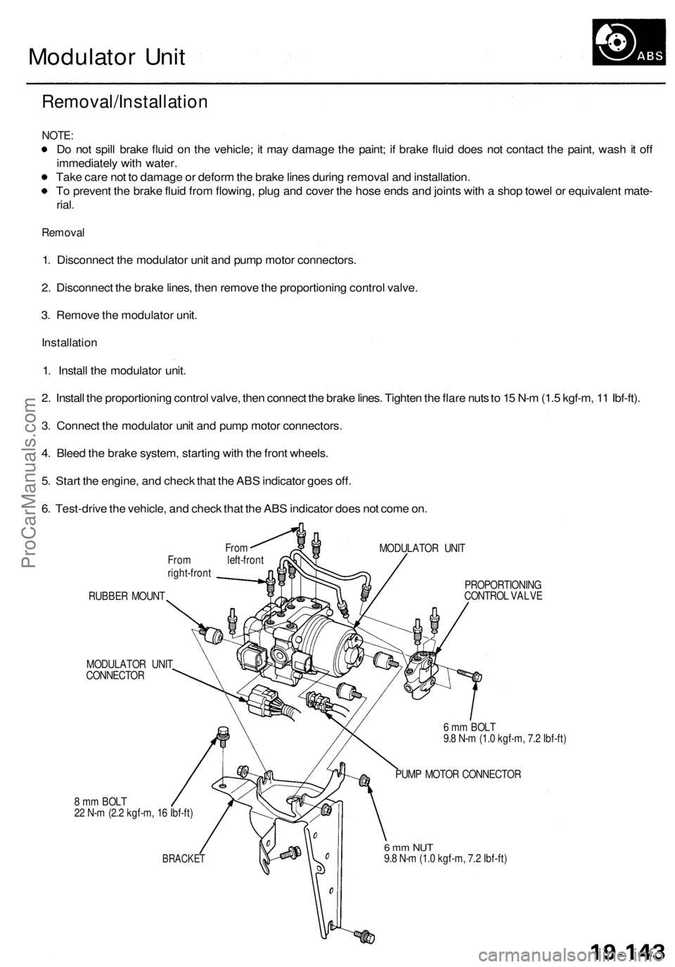
Modulator Unit
Removal/Installation
NOTE:
Do not spill brake fluid on the vehicle; it may damage the paint; if brake fluid does not contact the paint, wash it off
immediately with water.
Take care not to damage or deform the brake lines during removal and installation.
To prevent the brake fluid from flowing, plug and cover the hose ends and joints with a shop towel or equivalent mate-
rial.
Removal
1. Disconnect the modulator unit and pump motor connectors.
2. Disconnect the brake lines, then remove the proportioning control valve.
3. Remove the modulator unit.
Installation
1. Install the modulator unit.
2. Install the proportioning control valve, then connect the brake lines. Tighten the flare nuts to 15 N-m (1.5 kgf-m, 11 Ibf-ft).
3. Connect the modulator unit and pump motor connectors.
4. Bleed the brake system, starting with the front wheels.
5. Start the engine, and check that the ABS indicator goes off.
6. Test-drive the vehicle, and check that the ABS indicator does not come on.
From
From left-front
right-front
MODULATOR UNIT
RUBBER MOUNT
MODULATOR UNIT
CONNECTOR
8 mm BOLT
22 N-m (2.2 kgf-m, 16 Ibf-ft)
BRACKET
PROPORTIONING
CONTROL VALVE
6 mm BOLT
9.8 N-m (1.0 kgf-m, 7.2 Ibf-ft)
PUMP MOTOR CONNECTOR
6 mm NUT
9.8 N-m (1.0 kgf-m, 7.2 Ibf-ft)ProCarManuals.com
Page 1245 of 1954
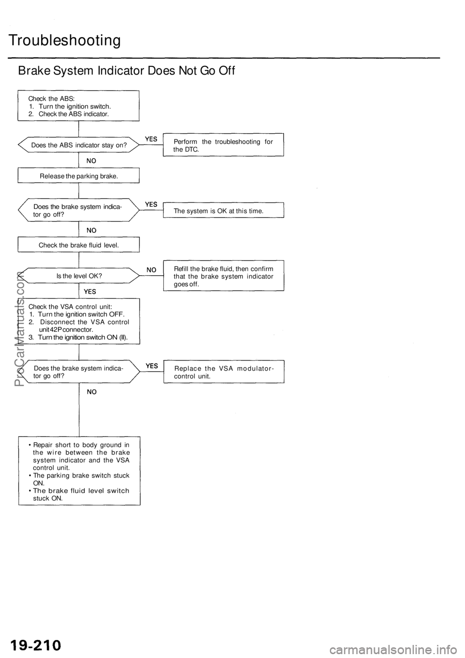
Troubleshooting
Brake System Indicator Does Not Go Off
Check the ABS:
1. Turn the ignition switch.
2. Check the ABS indicator.
Does the ABS indicator stay on?
Perform the troubleshooting for
the
DTC.
Release the parking brake.
Does the brake system indica-
tor go off?
The system is OK at this time.
Check the brake fluid level.
Is the level OK?
Refill the brake fluid, then confirm
that the brake system indicator
goes off.
Check the VSA control unit:
1. Turn the ignition switch OFF.
2. Disconnect the VSA control
unit 42P connector.
3. Turn the ignition switch ON (II).
Does the brake system indica-
tor go off?
Replace the VSA modulator-
control unit.
Repair short to body ground in
the wire between the brake
system indicator and the VSA
control unit.
The parking brake switch stuck
ON.
The brake fluid level switch
stuck ON.ProCarManuals.com