brake light ACURA RL KA9 1996 Service Repair Manual
[x] Cancel search | Manufacturer: ACURA, Model Year: 1996, Model line: RL KA9, Model: ACURA RL KA9 1996Pages: 1954, PDF Size: 61.44 MB
Page 171 of 1954
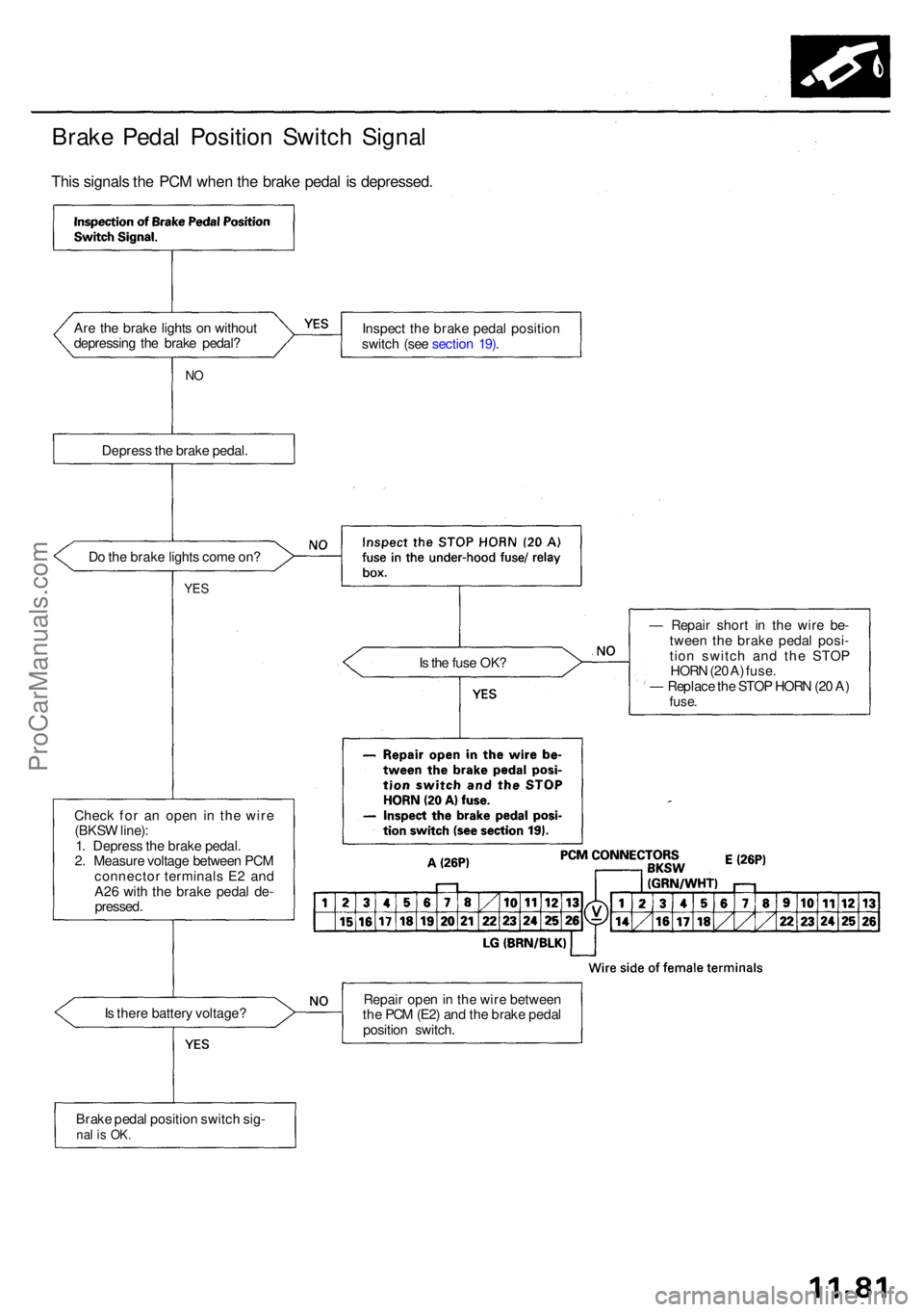
Brake Peda l Positio n Switc h Signa l
This signal s th e PC M whe n th e brak e peda l i s depressed .
Are th e brak e light s o n withou t
depressin g th e brak e pedal ? Inspec
t th e brak e peda l positio n
switc h (se e sectio n 19) .
NO
Depres s th e brak e pedal .
D o th e brak e light s com e on ?
YES
Is th e fus e OK ?
Chec k fo r a n ope n i n th e wir e
(BKS W line) :
1 . Depres s th e brak e pedal .
2 . Measur e voltag e betwee n PC M
connecto r terminal s E 2 an d
A2 6 wit h th e brak e peda l de -
pressed . —
Repai r shor t i n th e wir e be -
twee n th e brak e peda l posi -
tio n switc h an d th e STO P
HOR N (2 0 A ) fuse .
— Replac e th e STO P HOR N (2 0 A )
fuse .
Is ther e batter y voltage ? Repai
r ope n in th e wir e betwee n
th e PC M (E2 ) an d th e brak e peda l
positio n switch .
Brak e peda l positio n switc h sig -
nal i s OK .
ProCarManuals.com
Page 356 of 1954

Cruise Control
Control Unit Input Test (cont'd)
Cavity Wire
Test condition
Test: Desired result
Possible cause if result is not obtained
3
13
7
6
14
12
2
5
10
9
11
1
BLK
LT GRN
LT GRN/BLK
LT GRN/RED
PNK
BLU/WHT
GRY
GRN/WHT
BLU/YEL
BRN
BRN/BLK
BRN/WHT
Under all conditions
Ignition switch ON (II) and
main switch ON
Resume button pushed
Cancel button pushed
Set button pushed
Cancel button pushed
Shift lever in , or
Ignition switch ON (II), and
main switch ON; raise the
front of the vehicle, and rotate
one wheel slowly while
holding the other wheel.
Ignition switch ON (II), main
switch ON; brake pedal
pressed, then released
Brake pedal pressed then
released
Ignition switch ON (II)
Under all conditions
Under all conditions
Under all conditions
Check for continuity to ground:
There should be continuity.
Check for voltage to ground:
There should be battery voltage.
Check for voltage to ground:
There should be battery voltage.
When testing terminal No. 7, there
should be no voltage on terminal No. 6.
Check for voltage to ground:
There should be battery voltage.
When testing terminal No. 7, there
should be voltage on terminal No. 6.
Check for voltage to ground:
There should be battery voltage.
When testing terminal No. 6, there
should be no voltage on terminal No. 7.
Check for voltage to ground:
There should be battery voltage.
When testing terminal No. 6, there
should be voltage on terminal No. 7.
Check for continuity to ground:
There should be continuity.
NOTE: There should be no continuity
when the shift lever is in other positions.
Check for voltage between the
BLU/ WHT and BLK terminals:
There should be cycle 0 - 5 V or
battery voltage.
Check for voltage to ground:
There should be 0 V with the pedal
pressed, and battery voltage with
the pedal released.
Check for voltage to ground:
There should be battery voltage with
the pedal pressed, and 0 V with the
pedal released.
Attach to ground:
The cruise light in the gauge assembly
should come on.
Check for resistance to ground:
There should be 80 -120
Check for resistance to ground:
There should be 70 -110
Check for resistance to ground:
There should be 40 - 60
• Poor ground (G401, G402)
• An open in the wire
• Blown No. 20 (20 A) fuse in the
under-dash fuse/relay box
• Faulty main switch
• An open in the wire
• Blown No. 39 (15 A) fuse in the
under-hood fuse/relay box
• Faulty horn relay
• Faulty set/resume/cancel switch
• Faulty cable reel
• An open in the wire
• Short between LT GRN/BLK and
LT GRN/RED wires
• Blown No. 39 (15 A) fuse in the
under-hood fuse/relay box
• Faulty horn relay
• Faulty set/resume/cancel switch
• Faulty cable reel
• An open in the wire
• Blown No. 39 (15 A) fuse in the
under-hood fuse/relay box
• Faulty horn relay
• Faulty set/resume/cancel switch
• Faulty cable reel
• An open in the wire
• Short between LT GRN/BLK and
LT GRN/RED wires
• Blown No. 39 (15 A) fuse in the
under-hood fuse/relay box
• Faulty horn relay
• Faulty set/resume/cancel switch
• Faulty cable reel
• An open in the wire
• Faulty A/T gear position switch
• Poor ground (G401, G402)
• An open in the wire
• Faulty vehicle speed sensor (VSS)
• An open in the wire
• Short to ground
• Blown No. 39 (15 A) fuse in the
under-hood fuse/relay box
• Faulty brake switch
• An open in the wire
• Blown No. 39 (15 A) fuse in the
under-hood fuse/relay box
• Faulty brake switch
• An open in the wire
• Blown bulb
• Faulty gauge circuit
• An open in the wire
• Faulty actuator solenoid
• An open in the wireProCarManuals.com
Page 621 of 1954
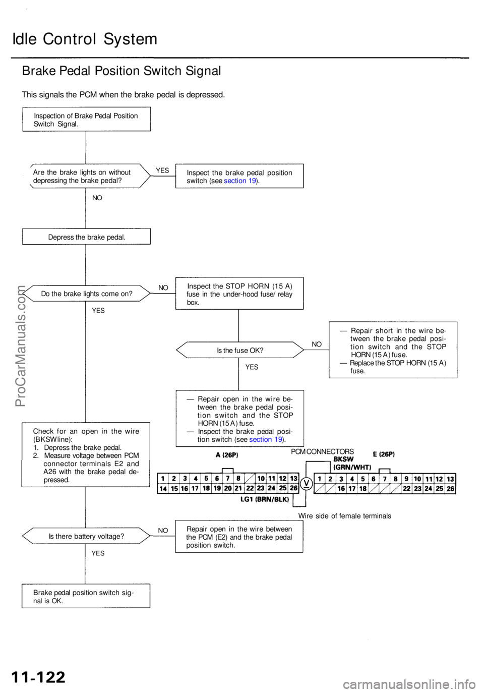
Idle Contro l Syste m
Brake Peda l Positio n Switc h Signa l
Are th e brak e light s o n withou t
depressin g th e brak e pedal ? Inspec
t th e brak e peda l positio n
switc h (se e sectio n 19 ).
N O
Depres s th e brak e pedal .
D o th e brak e light s com e on ?
YES
Is th e fus e OK ?NO
Chec k fo r a n ope n i n th e wir e
(BKS W line) :
1 . Depres s th e brak e pedal .
2 . Measur e voltag e betwee n PC M
connecto r terminal s E 2 an d
A2 6 wit h th e brak e peda l de -
pressed . —
Repai r shor t i n th e wire be-
twee n th e brak e peda l posi -
tio n switc h an d th e STO P
HOR N (1 5 A ) fuse .
— Replac e th e STO P HOR N (1 5 A )
fuse .
Wire sid e o f femal e terminal s
I s ther e batter y voltage ? Repai
r ope n in th e wir e betwee n
th e PC M (E2 ) an d th e brak e peda l
positio n switch .
Brak e peda l positio n switc h sig -
nal i s OK .
YES
NO
— Repai r ope n i n th e wir e be -
twee n th e brak e peda l posi -
tio n switc h an d th e STO P
HOR N (1 5 A ) fuse .
— Inspec t th e brak e peda l posi -
tio n switc h (se e sectio n 19 ).
PC M CONNECTOR S
YES
NOInspec t th e STO P HOR N (1 5 A )
fus e i n th e under-hoo d fuse / rela y
box.
YES
Inspectio n o f Brak e Peda l Positio n
Switc h Signal .
This signal s th e PC M whe n th e brak e peda l i s depressed .
ProCarManuals.com
Page 1051 of 1954
Inspection and Adjustment
Brake Pedal
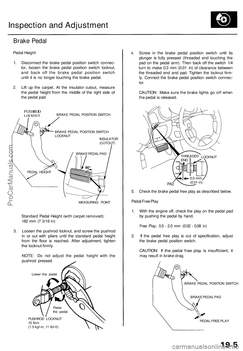
Pedal Height
1. Disconnect the brake pedal position switch connec-
tor, loosen the brake pedal position switch locknut,
and back off the brake pedal position switch
until it is no longer touching the brake pedal.
2.
Lift up the carpet. At the insulator cutout, measure
the pedal height from the middle of the right side of
the pedal pad.
PUSHROD
LOCKNUT
BRAKE PEDAL POSITION SWITCH
BRAKE PEDAL POSITION SWITCH
LOCKNUT
INSULATOR
(CUTOUT)
MEASURING POINT
Standard Pedal Height (with carpet removed):
182 mm (7
3/16
in)
3. Loosen the pushrod locknut, and screw the pushrod
in or out with pliers until the standard pedal height
from the floor is reached. After adjustment, tighten
the locknut firmly.
NOTE: Do not adjust the pedal height with the
pushrod pressed.
Lower the pedal
PUSHROD LOCKNUT
15 N-m
(1.5 kgf-m, 11 Ibf-ft)
4.
Screw in the brake pedal position switch until its
plunger is fully pressed (threaded end touching the
pad on the pedal arm). Then back off the switch 1/4
turn to make 0.3 mm (0.01 in) of clearance between
the threaded end and pad. Tighten the locknut firm-
ly. Connect the brake pedal position switch connec-
tor.
CAUTION: Make sure the brake lights go off when
the pedal is released.
PAD
5. Check the brake pedal free play as described below.
Pedal Free Play
1. With the engine off, check the play on the pedal pad
by pushing the pedal by hand.
Free Play: 0.5 - 2.0 mm (0.02 - 0.08 in)
2. If the pedal free play is out of specification, adjust
the brake pedal position switch.
CAUTION: If the pedal free play is insufficient, it
may result in brake drag.
BRAKE PEDAL POSITION SWITCH
BRAKE PEDAL PAD
PEDAL FREE PLAY
LOCKNUT
THREADED
END
0.3 mm
(0.01
in)
BRAKE PEDAL PAD
PEDAL HEIGHT
Raise
the pedalProCarManuals.com
Page 1052 of 1954
Inspection an d Adjustmen t
Parking Brak e Peda l
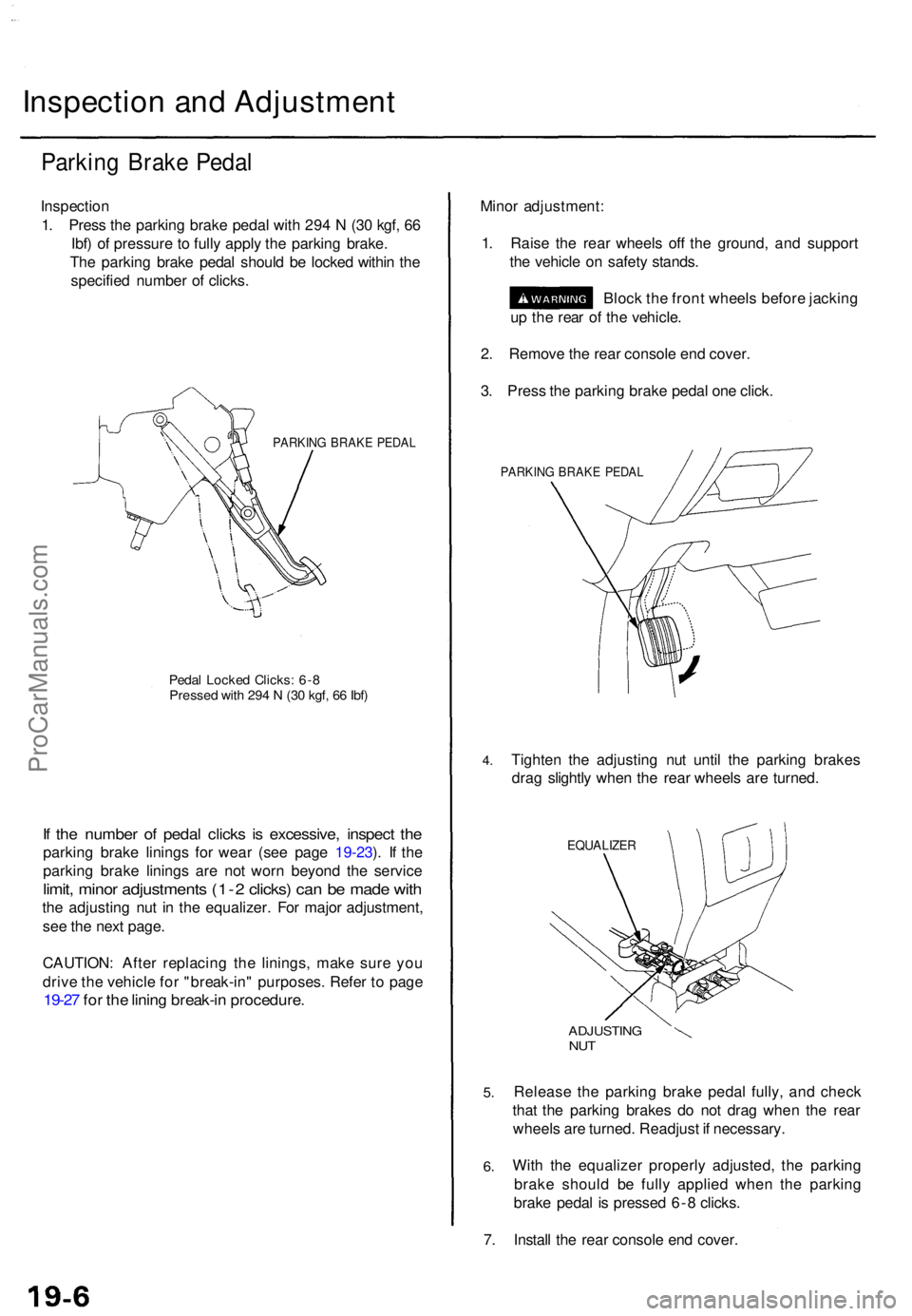
Inspectio n
1 . Pres s th e parkin g brak e peda l wit h 29 4 N (3 0 kgf , 6 6
Ibf ) o f pressur e to full y appl y th e parkin g brake .
Th e parkin g brak e peda l shoul d b e locke d withi n th e
specifie d numbe r o f clicks .
PARKIN G BRAK E PEDA L
Pedal Locke d Clicks : 6- 8Presse d wit h 29 4 N (3 0 kgf , 6 6 Ibf )
If th e numbe r o f peda l click s i s excessive , inspec t th e
parkin g brak e lining s fo r wea r (se e pag e 19-23 ). I f th e
parkin g brak e lining s ar e no t wor n beyon d th e servic e
limit, mino r adjustment s (1- 2 clicks ) ca n b e mad e wit h
the adjustin g nu t i n th e equalizer . Fo r majo r adjustment ,
se e th e nex t page .
CAUTION : Afte r replacin g th e linings , mak e sur e yo u
driv e th e vehicl e fo r "break-in " purposes . Refe r t o pag e
19-27 fo r th e linin g break-i n procedure .
Minor adjustment :
1 . Rais e th e rea r wheel s of f th e ground , an d suppor t
th e vehicl e o n safet y stands .
Bloc k th e fron t wheel s befor e jackin g
u p th e rea r o f th e vehicle .
2 . Remov e th e rea r consol e en d cover .
3 . Pres s th e parkin g brak e peda l on e click .
PARKIN G BRAK E PEDA L
4.Tighte n th e adjustin g nu t unti l th e parkin g brake s
dra g slightl y whe n th e rea r wheel s ar e turned .
EQUALIZE R
5.
6.
ADJUSTIN GNUT
Releas e th e parkin g brak e peda l fully , an d chec k
tha t th e parkin g brake s d o no t dra g whe n th e rea r
wheel s ar e turned . Readjus t i f necessary .
Wit h th e equalize r properl y adjusted , th e parkin g
brak e shoul d b e full y applie d whe n th e parkin g
brak e peda l i s presse d 6- 8 clicks .
7 . Instal l th e rea r consol e en d cover .
ProCarManuals.com
Page 1055 of 1954
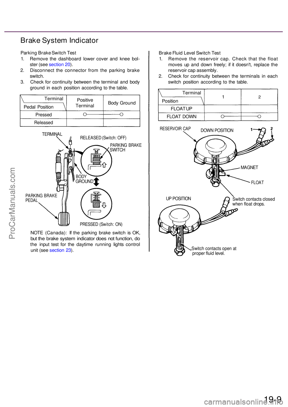
Brake Syste m Indicato r
Parking Brak e Switc h Tes t
1 . Remov e th e dashboar d lowe r cove r an d kne e bol -
ste r (se e sectio n 20 ).
2 . Disconnec t th e connecto r fro m th e parkin g brak e
switch .
3 . Chec k fo r continuit y betwee n th e termina l an d bod y
groun d i n eac h positio n accordin g t o th e table .
TERMINA LRELEASE D (Switch : OFF )
PARKIN G BRAK ESWITCH
PARKIN G BRAK EPEDAL
PRESSE D (Switch : ON )
NOT E (Canada) : I f th e parkin g brak e switc h i s OK ,
but th e brak e syste m indicato r doe s no t function , d o
th e inpu t tes t fo r th e daytim e runnin g light s contro l
uni t (se e sectio n 23 ). Brak
e Flui d Leve l Switc h Tes t
1 . Remov e th e reservoi r cap . Chec k tha t th e floa t
move s u p an d dow n freely ; i f i t doesn't , replac e th e
reservoi r ca p assembly .
2 . Chec k fo r continuit y betwee n th e terminal s i n eac h
switc h positio n accordin g t o th e table .
RESERVOI R CA PDOW N POSITIO N
FLOAT
Switch contact s close dwhen floa t drops .
sSwitch contact s ope n a tprope r flui d level .
19-9
UP POSITIO N
MAGNET
BODYGROUN D
Positive
Termina lBod
y Groun d
Termina
l
Peda l Positio n
Pressed
Release d
Termina l
Positio n
FLOA T U P
FLOA T DOW N
12
ProCarManuals.com
Page 1056 of 1954
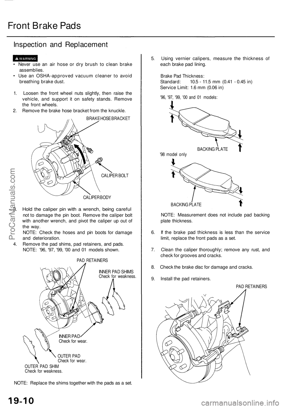
Front Brak e Pad s
Inspectio n an d Replacemen t
• Neve r us e a n ai r hos e o r dr y brus h t o clea n brake
assemblies .
• Us e a n OSHA-approve d vacuu m cleane r t o avoi d
breathin g brak e dust .
1 . Loose n th e fron t whee l nut s slightly , the n rais e th e
vehicle , an d suppor t i t o n safet y stands . Remov e
th e fron t wheels .
2 . Remov e th e brak e hos e bracke t fro m th e knuckle .
BRAKE HOS E BRACKE T
CALIPE R BOL T
CALIPE R BOD Y
3. Hol d th e calipe r pi n wit h a wrench , bein g carefu l
not t o damag e th e pi n boot . Remov e th e calipe r bol t
wit h anothe r wrench , an d pivo t th e calipe r u p ou t o f
the way .
NOTE : Chec k th e hose s an d pi n boot s fo r damag e
an d deterioration .
4 . Remov e th e pa d shims , pa d retainers , an d pads .
NOTE : '96 , '97 , '99 , '0 0 an d 0 1 model s shown .
PAD RETAINER S
INNER PA D SHIM SCheck fo r weakness .
OUTE R PA D
Chec k fo r wear .
OUTE R PA D SHI M
Chec k fo r weakness .
NOTE: Replac e th e shim s togethe r wit h th e pad s a s a set . 5
. Usin g vernie r calipers , measur e th e thicknes s of
eac h brak e pa d lining .
Brake Pa d Thickness :
Standard: 10. 5 - 11. 5 m m (0.4 1 - 0.4 5 in )
Servic e Limit : 1. 6 m m (0.0 6 in )
'96 , '97 , '99 , '0 0 an d 0 1 models :
BACKIN G PLAT E
NOTE: Measuremen t doe s no t includ e pa d backin g
plat e thickness .
6 . I f th e brak e pa d thicknes s i s les s tha n th e servic e
limit , replac e th e fron t pad s a s a set .
7 . Clea n th e calipe r thoroughly ; remov e an y rust , an d
chec k fo r groove s an d cracks .
8 . Chec k th e brak e dis c fo r damag e an d cracks .
9 . Instal l th e pa d retainers .
PAD RETAINER S
BACKIN
G PLAT E
'9 8 mode l onl y
INNE R PA DChec k fo r wear .
ProCarManuals.com
Page 1058 of 1954
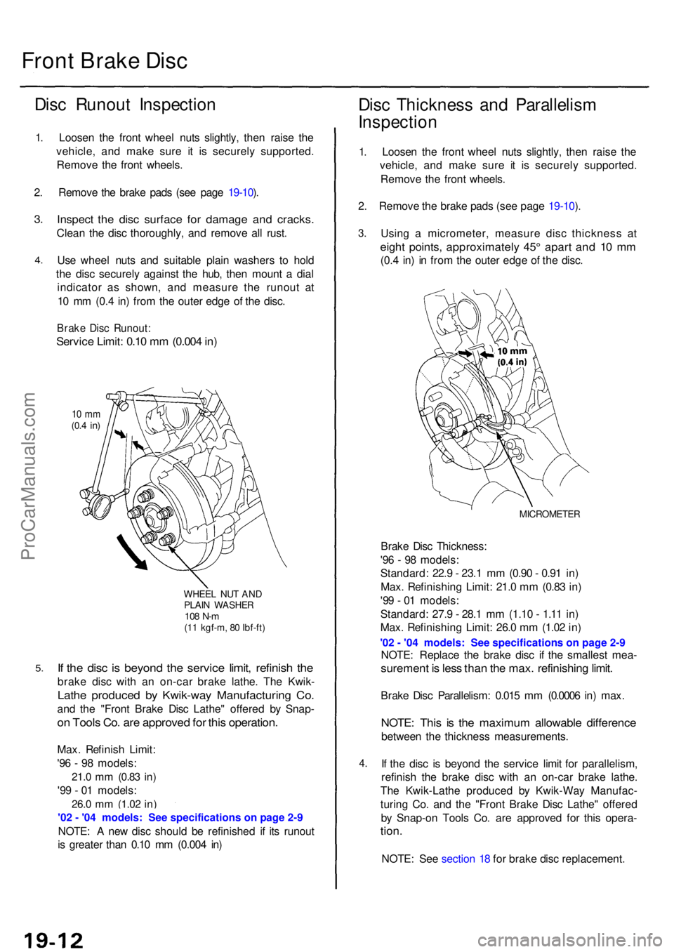
Front Brak e Dis c
Disc Runou t Inspectio n
1. Loose n th e fron t whee l nut s slightly , the n rais e th e
vehicle , an d mak e sur e i t i s securel y supported .
Remov e th e fron t wheels .
2 . Remov e th e brak e pad s (se e pag e 19-10 ).
3 .
4 .
5 .
Inspec t th e dis c surfac e fo r damag e an d cracks .
Clean th e dis c thoroughly , an d remov e al l rust .
Us e whee l nut s an d suitabl e plai n washer s t o hol d
th e dis c securel y agains t th e hub , the n moun t a dia l
indicato r a s shown , an d measur e th e runou t a t
1 0 m m (0. 4 in ) fro m th e oute r edg e o f th e disc .
Brak e Dis c Runout :
Service Limit : 0.1 0 m m (0.00 4 in )
10 m m(0.4 in )
WHEE L NU T AN DPLAI N WASHE R108 N- m(11 kgf-m , 8 0 Ibf-ft )
If th e dis c i s beyon d th e servic e limit , refinis h th e
brak e dis c wit h a n on-ca r brak e lathe . Th e Kwik -
Lathe produce d b y Kwik-wa y Manufacturin g Co .
and th e "Fron t Brak e Dis c Lathe " offere d b y Snap -
on Tool s Co . ar e approve d fo r thi s operation .
Max. Refinis h Limit :
'9 6 - 9 8 models :
21.0 mm (0.8 3 in)
'99 - 0 1 models :
26.0 mm (1.0 2 in)
NOTE : A ne w dis c shoul d b e refinishe d i f it s runou t
i s greate r tha n 0.1 0 m m (0.00 4 in )
Dis c Thicknes s an d Parallelis m
Inspectio n
1. Loose n th e fron t whee l nut s slightly , the n rais e th e
vehicle , an d mak e sur e i t i s securel y supported .
Remov e th e fron t wheels .
2 . Remov e th e brak e pad s (se e pag e 19-10 ).
3 .
4.
Usin g a micrometer , measur e dis c thicknes s a t
eigh t points , approximatel y 45 ° apar t an d 1 0 m m
(0.4 in ) i n fro m th e oute r edg e o f th e disc .
MICROMETE R
Brake Dis c Thickness :
'9 6 - 9 8 models :
Standard : 22. 9 - 23. 1 m m (0.9 0 - 0.9 1 in )
Max . Refinishin g Limit : 21. 0 m m (0.8 3 in )
'9 9 - 0 1 models :
Standard : 27. 9 - 28. 1 m m (1.1 0 - 1.1 1 in )
Max . Refinishin g Limit : 26. 0 m m (1.0 2 in )
NOTE : Replac e th e brak e dis c i f th e smalles t mea -
suremen t i s les s tha n th e max . refinishin g limit .
Brak e Dis c Parallelism : 0.01 5 m m (0.000 6 in ) max .
NOTE : Thi s i s th e maximu m allowabl e differenc e
between th e thicknes s measurements .
I f th e dis c i s beyon d th e servic e limi t fo r parallelism ,
refinis h th e brak e dis c wit h a n on-ca r brak e lathe .
Th e Kwik-Lath e produce d b y Kwik-Wa y Manufac -
turin g Co . an d th e "Fron t Brak e Dis c Lathe " offere d
b y Snap-o n Tool s Co . ar e approve d fo r thi s opera -
tion.
NOTE : Se e sectio n 1 8 fo r brak e dis c replacement .
ProCarManuals.com
Page 1064 of 1954
Master Cylinder/Brak e Booste r
Brake Booste r Inspectio n
Functiona l Tes t
1 . Wit h th e engin e stopped , pres s th e brak e peda l sev -
eral time s t o deplet e th e vacuu m reservoir , the n
pres s th e peda l har d an d hol d i t fo r 1 5 seconds . I f
th e peda l sinks , eithe r th e maste r cylinde r i s
bypassin g internally , o r th e brak e syste m (maste r
cylinder , lines , modulator , o r caliper ) i s leaking .
2 . Star t th e engin e wit h th e peda l pressed . I f th e peda l
sinks slightly , th e vacuu m booste r i s operatin g nor -
mally . I f th e peda l heigh t doe s no t vary , th e booste r
o r chec k valv e is faulty .
3. Wit h th e engin e running , pres s th e brak e peda l light -
ly. Appl y jus t enoug h pressur e t o hol d bac k auto -
mati c transmissio n creep . I f th e brak e peda l sink s
mor e tha n 2 5 m m (1. 0 in. ) i n 3 minutes , th e maste r
cylinde r i s faulty . A sligh t chang e i n peda l heigh t
whe n th e A/ C compresso r cycle s o n an d of f i s nor -
mal . (Th e A/ C compresso r loa d change s th e vacuu m
availabl e to th e booster. )
Leak Tes t
1 . Pres s th e brak e peda l wit h th e engin e running , the n
sto p th e engine . I f th e peda l heigh t doe s no t var y
whil e presse d fo r 3 0 seconds , th e vacuu m booste r i s
OK . I f th e peda l rises , th e booste r i s faulty .
2 . Wit h th e engin e stopped , pres s th e brak e peda l sev -
era l time s usin g norma l pressure . Whe n th e peda l i s
firs t pressed , i t shoul d b e low . O n consecutiv e appli -
cations , th e peda l heigh t shoul d graduall y rise . I f th e
peda l positio n doe s no t vary , chec k th e booste r
chec k valve .
Booste r Chec k Valv e Tes t
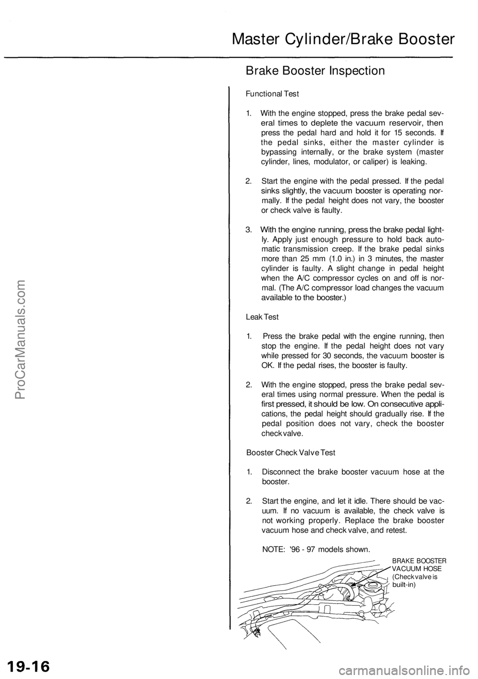
1 . Disconnec t th e brak e booste r vacuu m hos e a t th e
booster .
2 . Star t th e engine , an d le t i t idle . Ther e shoul d b e vac -
uum . I f n o vacuu m is available , th e chec k valv e i s
no t workin g properly . Replac e th e brak e booste r
vacuu m hos e an d chec k valve , an d retest .
NOTE : '9 6 - 9 7 model s shown .
BRAKE BOOSTE RVACUUM HOS E
(Chec k valv e is
built-in )
ProCarManuals.com
Page 1065 of 1954
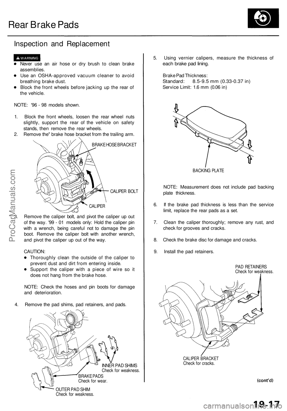
Rear Brake Pads
Inspection and Replacement
Never use an air hose or dry brush to clean brake
assemblies.
Use an OSHA-approved vacuum cleaner to avoid
breathing brake dust.
Block the front wheels before jacking up the rear of
the vehicle.
NOTE: '96 - 98 models shown.
1. Block the front wheels, loosen the rear wheel nuts
slightly, support the rear of the vehicle on safety
stands, then remove the rear wheels.
2. Remove the" brake hose bracket from the trailing arm.
BRAKE HOSE BRACKET
CALIPER BOLT
3.
CALIPER
Remove the caliper bolt, and pivot the caliper up out
of the way. '99 - 01 models only: Hold the caliper pin
with a wrench, being careful not to damage the pin
boot. Remove the caliper bolt with another wrench,
and pivot the caliper up out of the way.
CAUTION:
Thoroughly clean the outside of the caliper to
prevent dust and dirt from entering inside.
Support the caliper with a piece of wire so it
does not hang from the brake hose.
NOTE: Check the hoses and pin boots for damage
and deterioration.
4. Remove the pad shims, pad retainers, and pads.
INNER PAD SHIMS
Check for weakness.
BRAKE PADS
Check for wear.
OUTER PAD SHIM
Check for weakness.
5. Using vernier calipers, measure the thickness of
each brake pad lining.
Brake Pad Thickness:
Standard: 8.5-9.5 mm (0.33-0.37 in)
Service Limit: 1.6 mm (0.06 in)
BACKING PLATE
NOTE: Measurement does not include pad backing
plate thickness.
6. If the brake pad thickness is less than the service
limit, replace the rear pads as a set.
7. Clean the caliper thoroughly; remove any rust, and
check for grooves and cracks.
8. Check the brake disc for damage and cracks.
9. Install the pad retainers.
PAD RETAINERS
Check for weakness.
CALIPER BRACKET
Check for cracks.ProCarManuals.com