catalytic converter ACURA RL KA9 1996 Service Repair Manual
[x] Cancel search | Manufacturer: ACURA, Model Year: 1996, Model line: RL KA9, Model: ACURA RL KA9 1996Pages: 1954, PDF Size: 61.44 MB
Page 371 of 1954
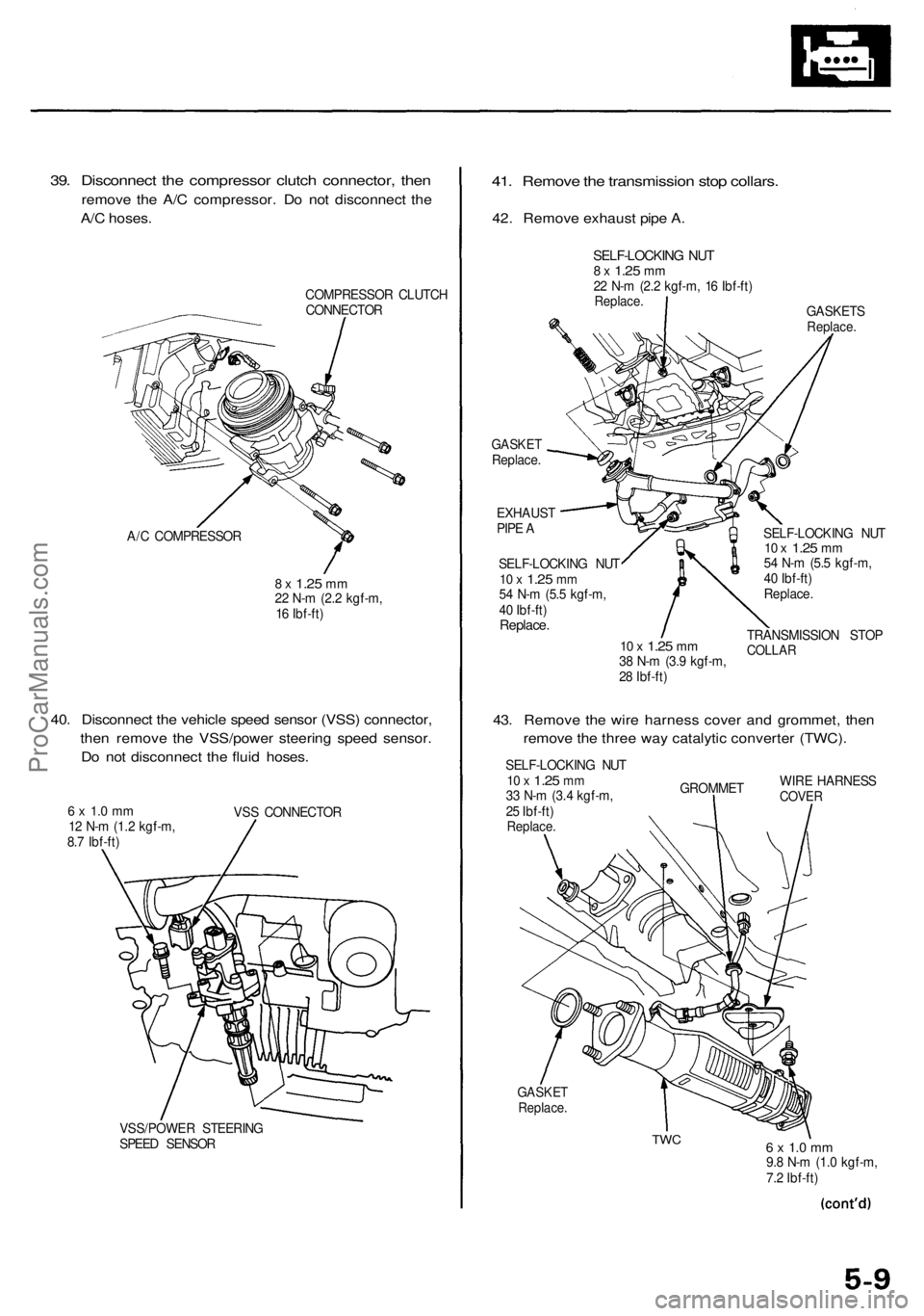
39. Disconnect the compressor clutch connector, then
remove the A/C compressor. Do not disconnect the
A/C hoses.
COMPRESSOR CLUTCH
CONNECTOR
A/C COMPRESSOR
8 x
1.25
mm
22 N-m (2.2 kgf-m,
16 Ibf-ft)
40. Disconnect the vehicle speed sensor (VSS) connector,
then remove the VSS/power steering speed sensor.
Do not disconnect the fluid hoses.
6 x 1.0 mm
12 N-m (1.2 kgf-m,
8.7 Ibf-ft)
VSS CONNECTOR
VSS/POWER STEERING
SPEED SENSOR
41. Remove the transmission stop collars.
42. Remove exhaust pipe A.
GASKETS
Replace.
GASKET
Replace.
EXHAUST
PIPE A
SELF-LOCKING NUT
10 x
1.25
mm
54 N-m (5.5 kgf-m,
40 Ibf-ft)
Replace.
10 x
1.25
mm
38 N-m (3.9 kgf-m,
28 Ibf-ft)
SELF-LOCKING NUT
10 x
1.25
mm
54 N-m (5.5 kgf-m,
40 Ibf-ft)
Replace.
TRANSMISSION STOP
COLLAR
43. Remove the wire harness cover and grommet, then
remove the three way catalytic converter (TWC).
SELF-LOCKING NUT
10 x
1.25
mm
33 N-m (3.4 kgf-m,
25 Ibf-ft)
Replace.
GROMMET
WIRE HARNESS
COVER
GASKET
Replace.
TWC
6 x 1.0 mm
9.8 N-m (1.0 kgf-m,
7.2 Ibf-ft)
SELF-LOCKING NUT
8 x
1.25
mm
22 N-m (2.2 kgf-m, 16 Ibf-ft)
Replace.ProCarManuals.com
Page 512 of 1954
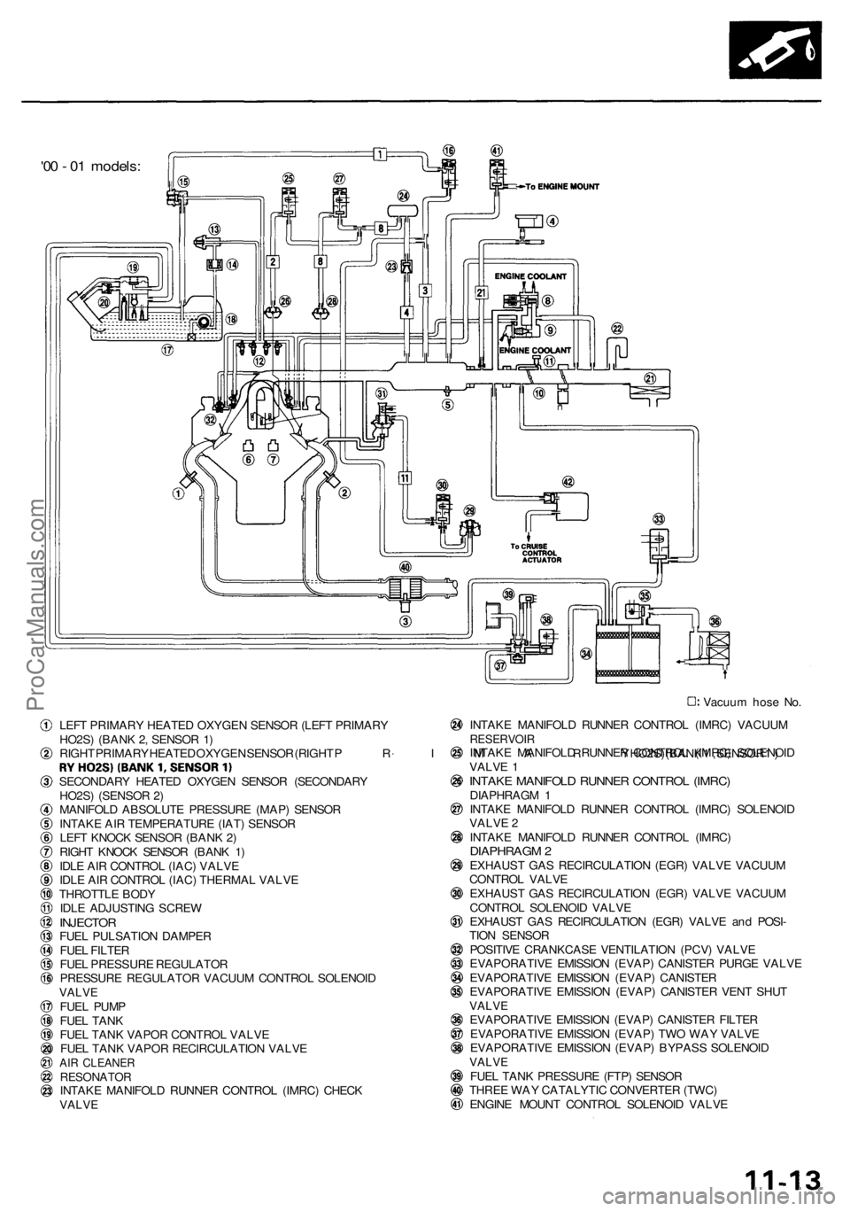
'00 - 01 models:
Vacuum hose No.
LEFT PRIMARY HEATED OXYGEN SENSOR (LEFT PRIMARY
HO2S) (BANK 2, SENSOR 1)
RIGHT PRIMARY HEATED OXYGEN SENSOR (RIGHT
PRIMARY
HO2S) (BANK
1,
SENSOR
1)
SECONDARY HEATED OXYGEN SENSOR (SECONDARY
HO2S) (SENSOR 2)
MANIFOLD ABSOLUTE PRESSURE (MAP) SENSOR
INTAKE AIR TEMPERATURE (IAT) SENSOR
LEFT KNOCK SENSOR (BANK 2)
RIGHT KNOCK SENSOR (BANK 1)
IDLE AIR CONTROL (IAC) VALVE
IDLE AIR CONTROL (IAC) THERMAL VALVE
THROTTLE BODY
IDLE ADJUSTING SCREW
INJECTOR
FUEL PULSATION DAMPER
FUEL FILTER
FUEL PRESSURE REGULATOR
PRESSURE REGULATOR VACUUM CONTROL SOLENOID
VALVE
FUEL PUMP
FUEL TANK
FUEL TANK VAPOR CONTROL VALVE
FUEL TANK VAPOR RECIRCULATION VALVE
AIR CLEANER
RESONATOR
INTAKE MANIFOLD RUNNER CONTROL (IMRC) CHECK
VALVE
INTAKE MANIFOLD RUNNER CONTROL (IMRC) VACUUM
RESERVOIR
INTAKE MANIFOLD RUNNER CONTROL (IMRC) SOLENOID
VALVE 1
INTAKE MANIFOLD RUNNER CONTROL (IMRC)
DIAPHRAGM 1
INTAKE MANIFOLD RUNNER CONTROL (IMRC) SOLENOID
VALVE 2
INTAKE MANIFOLD RUNNER CONTROL (IMRC)
DIAPHRAGM 2
EXHAUST GAS RECIRCULATION (EGR) VALVE VACUUM
CONTROL VALVE
EXHAUST GAS RECIRCULATION (EGR) VALVE VACUUM
CONTROL SOLENOID VALVE
EXHAUST GAS RECIRCULATION (EGR) VALVE and POSI-
TION SENSOR
POSITIVE CRANKCASE VENTILATION (PCV) VALVE
EVAPORATIVE EMISSION (EVAP) CANISTER PURGE VALVE
EVAPORATIVE EMISSION (EVAP) CANISTER
EVAPORATIVE EMISSION (EVAP) CANISTER VENT SHUT
VALVE
EVAPORATIVE EMISSION (EVAP) CANISTER FILTER
EVAPORATIVE EMISSION (EVAP) TWO WAY VALVE
EVAPORATIVE EMISSION (EVAP) BYPASS SOLENOID
VALVE
FUEL TANK PRESSURE (FTP) SENSOR
THREE WAY CATALYTIC CONVERTER (TWC)
ENGINE MOUNT CONTROL SOLENOID VALVEProCarManuals.com
Page 560 of 1954
How to Set Readiness Codes
Catalytic Converter
NOTE:
• Do not turn the ignition switch OFF.
• When the battery negative cable is disconnected, all
readiness codes are cleared.
Required condition ('96 - 97 models):
• Ambient temperature between 32 - 95°F (0 - 35°C).
• Altitude below 2,400 m (7,874 ft.).
Required condition ('98 - 01 models):
Ambient temperature between 20 - 95°F (-7 - 35°C).
1. Connect the scan tool to the Data Link Connector
(DLC).
2. Start the engine. Hold it at 3,000 rpm with no load
(in Park or neutral) until the radiator fan comes on.
3. Drive for about 10 minutes without stopping on a
highway or freeway. Your speed can vary.
4. '96 - 97 models:
With the transmission in D4 position, drive at a
steady speed between 33 - 37 mph (53 - 59 km/h)
for 30 seconds.
'98 - 01 models:
With the A/T in D4 position, drive at a steady speed
between 50 - 62 mph (80 - 100 km/h) for 30 sec-
onds.
5. Do step 4 three times. Between each repetition,
close the throttle completely for 1 - 2 seconds. If the
engine is stopped during this part of the procedure,
go to step 3 and do the procedure again.
6. Check for the readiness code with the scan tool.
EGR Monitor
NOTE:
• Do not turn the ignition switch OFF.
• When the battery negative cable is disconnected, all
readiness codes are cleared.
Required condition ('96 - 97 models):
Altitude below 2,400 m (7,874 ft.).
1. Connect the scan tool to the Data Link Connector
(DLC).
2. Start the engine, and hold it at 3,000 rpm with no
load (in Park or neutral) until the radiator fan comes
on.
3. Drive at a steady speed with the transmission in D4
position, between 50 - 62 mph (80 - 100 km/h) for
more than 10 seconds.
4. With the A/T in D4 position, decelerate from 62 mph
(100 km/h) by completely releasing the throttle for
at least 5 seconds. If the engine is stopped during
this procedure, go to step 3 and do the procedure
again.
5. Check for the readiness code with the scan tool.
EVAP Leak Monitor
NOTE:
• When the battery negative cable is disconnected, all
readiness codes are cleared.
• If the engine is stopped while doing the procedure
between stops 6 and 16, do this procedure from step
1 again.
1. Make sure the gasoline level is 60 - 90% of fuel tank
capacity (not full).
2. Turn the ignition switch OFF.
3. Let the vehicle sit more than 8 hours.
4. '96 - 97 models:
Make sure the outside temperature is 32 - 95°F (0 -
35°C).
'98 - 01 models:
Make sure the outside temperature is 20 - 95°F (-7 -
35°C).
5. Connect the scan tool to the Data Link Connector
(DLC).
6. Start the engine and drive for about 15 minutes.
7. '96 - 97 models:
Keep the vehicle at a steady speed between 50 - 62
mph (80 - 100 km/h), without moving the accelera-
tor pedal, for about 1 minute.
'98 - 01 models:
Keep the vehicle at a steady speed between 50 - 70
mph (80 - 114 km/h), without moving the accelera-
tor pedal, for about 1 minute.
8. Stop the vehicle (do not stop engine).
9. Repeat steps 7 and 8 two more times.
10. Check for the readiness code with the scan tool. If
the readiness code does not set, go to step 11.
11. When ambient temperature is less than 32°F (0°C),
hold the engine at 3,000 rpm with no load (in Park
or neutral) until the radiator fan comes on.
12. When ambient temperature is more than 86°F
(30°C), remove the fuel fill cap, then install the fuel
fill cap.
13. After step 12, drive for about 20 minutes on a free-
way.
14. '96 - 97 models:
Keep the vehicle at a steady speed between 50 - 62
mph (80 - 100 km/h), without moving the accelera-
tor pedal, for about 1 minute.
'98 - 01 models:
Keep the vehicle at a steady speed between 50 - 70
mph (80 - 114 km/h), without moving the accelera-
tor pedal, for about 1 minute.
15. Stop the vehicle (do not stop the engine).
16. Repeat steps 14 and 15 two more times.
17. Check for the readiness code with the scan tool.ProCarManuals.com
Page 798 of 1954
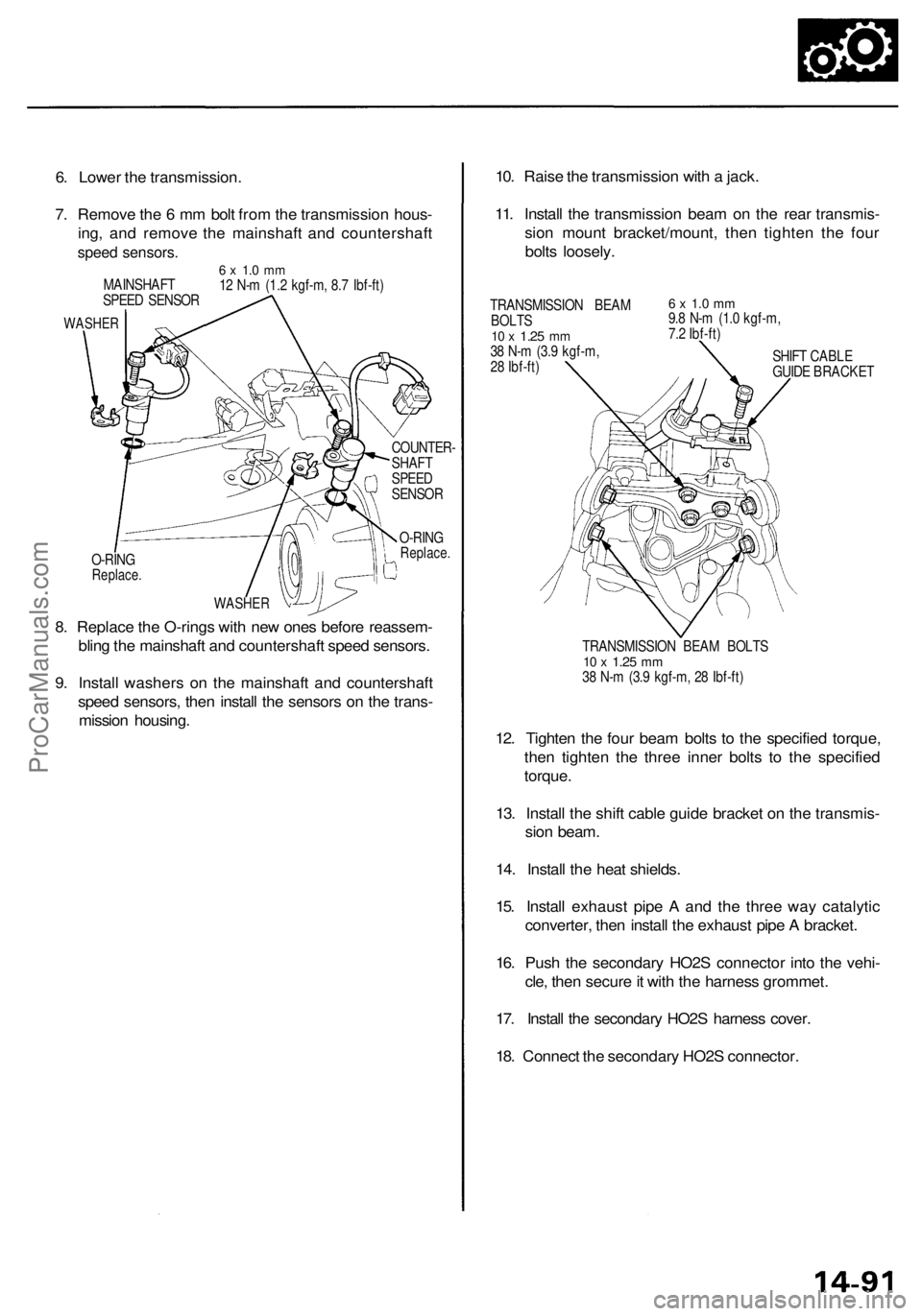
O-RING
Replace.
COUNTER-
SHAFT
SPEED
SENSOR
O-RING
Replace.
8. Replace the O-rings with new ones before reassem-
bling the mainshaft and countershaft speed sensors.
9. Install washers on the mainshaft and countershaft
speed sensors, then install the sensors on the trans-
mission housing.
10. Raise the transmission with a jack.
11. Install the transmission beam on the rear transmis-
sion mount bracket/mount, then tighten the four
bolts loosely.
TRANSMISSION BEAM
BOLTS
10 x
1.25
mm
38 N-m (3.9 kgf-m,
28 Ibf-ft)
6 x 1.0 mm
9.8 N-m (1.0 kgf-m,
7.2 Ibf-ft)
SHIFT CABLE
GUIDE BRACKET
TRANSMISSION BEAM BOLTS
10 x
1.25
mm
38 N-m (3.9 kgf-m, 28 Ibf-ft)
12. Tighten the four beam bolts to the specified torque,
then tighten the three inner bolts to the specified
torque.
13. Install the shift cable guide bracket on the transmis-
sion beam.
14. Install the heat shields.
15. Install exhaust pipe A and the three way catalytic
converter, then install the exhaust pipe A bracket.
16. Push the secondary HO2S connector into the vehi-
cle, then secure it with the harness grommet.
17. Install the secondary HO2S harness cover.
18. Connect the secondary HO2S connector.
6. Lower the transmission.
7. Remove the 6 mm bolt from the transmission hous-
ing, and remove the mainshaft and countershaft
speed sensors.
6 x 1.0 mm
12 N-m (1.2 kgf-m, 8.7 Ibf-ft)
MAINSHAFT
SPEED SENSOR
WASHER
WASHERProCarManuals.com
Page 824 of 1954
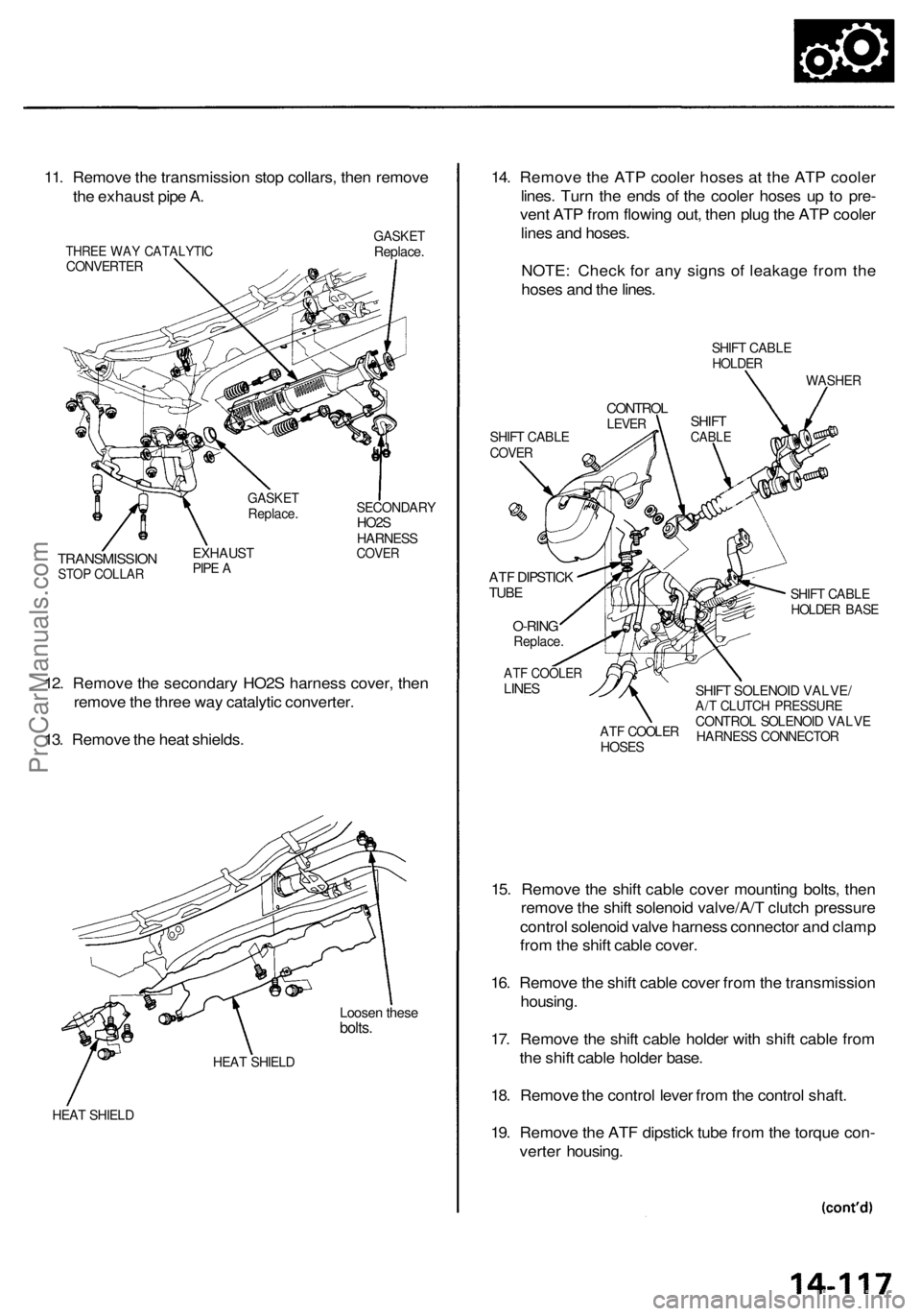
11. Remove the transmission stop collars, then remove
the exhaust pipe A.
THREE WAY CATALYTIC
CONVERTER
GASKET
Replace.
TRANSMISSION
STOP COLLAR
EXHAUST
PIPE A
SECONDARY
HO2S
HARNESS
COVER
12. Remove the secondary HO2S harness cover, then
remove the three way catalytic converter.
13. Remove the heat shields.
Loosen these
bolts.
HEAT SHIELD
HEAT SHIELD
14. Remove the ATP cooler hoses at the ATP cooler
lines. Turn the ends of the cooler hoses up to pre-
vent ATP from flowing out, then plug the ATP cooler
lines and hoses.
NOTE: Check for any signs of leakage from the
hoses and the lines.
SHIFT CABLE
HOLDER
WASHER
SHIFT CABLE
COVER
ATF DIPSTICK
TUBE
O-RING
Replace.
SHIFT CABLE
HOLDER BASE
15. Remove the shift cable cover mounting bolts, then
remove the shift solenoid valve/A/T clutch pressure
control solenoid valve harness connector and clamp
from the shift cable cover.
16. Remove the shift cable cover from the transmission
housing.
17. Remove the shift cable holder with shift cable from
the shift cable holder base.
18. Remove the control lever from the control shaft.
19. Remove the ATF dipstick tube from the torque con-
verter housing.
GASKET
Replace.
ATF COOLER
LINES
ATF COOLER
HOSES
SHIFT SOLENOID VALVE/
A/T CLUTCH PRESSURE
CONTROL SOLENOID VALVE
HARNESS CONNECTOR
CONTROL
LEVER
SHIFT
CABLEProCarManuals.com