change time ACURA RL KA9 1996 Service Repair Manual
[x] Cancel search | Manufacturer: ACURA, Model Year: 1996, Model line: RL KA9, Model: ACURA RL KA9 1996Pages: 1954, PDF Size: 61.44 MB
Page 139 of 1954
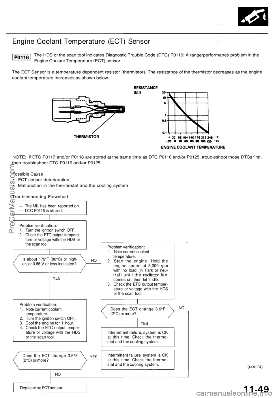
Engine Coolant Temperature (ECT) Sensor
The HDS or the scan tool indicates Diagnostic Trouble Code (DTC) P0116: A range/performance problem in the
Engine Coolant Temperature (ECT) sensor.
The ECT Sensor is a temperature dependent resistor (thermistor). The resistance of the thermistor decreases as the engine
coolant temperature increases as shown below.
NOTE: If DTC P0117 and/or P0118 are stored at the same time as DTC P0116 and/or P0125, troubleshoot those DTCs first,
then troubleshoot DTC P0116 and/or P0125.
Possible Cause
• ECT sensor deterioration
• Malfunction in the thermostat and the cooling system
Troubleshooting Flowchart
— The MIL has been reported on.
— DTC P0116 is stored.
Problem verification:
1. Turn the ignition switch OFF.
2. Check the ETC output tempera-
ture or voltage with the HDS or
the scan tool.
Is about 176°F (80°C) or high-
er, or 0.86 V or less indicated?
YES
Problem verification:
1. Note current coolant
temperature.
2. Turn the ignition switch OFF.
3. Cool the engine for 1 hour.
4. Check the ETC output temper-
ature or voltage with the HDS
or the scan tool.
Does the ECT change 3.6°F
(2°C) or more?
NO
Replace the ECT sensor.
NO
YES
Problem verification:
1. Note current coolant
temperature.
2. Start the engine. Hold the
engine speed at 3,000 rpm
with no load (in Park or neu-
tral)
until
the
radiator
fan
comes on, then let it idle.
3. Check the ETC output temper-
ature or voltage with the HDS
or the scan tool.
Does the ECT change 3.6°F
(2°C) or more?
NO
YES
Intermittent failure, system is OK
at this time. Check the thermo-
stat and the cooling system.
Intermittent failure, system is OK
at this time. Check the thermo-
stat and the cooling system.
(cont'd)ProCarManuals.com
Page 151 of 1954
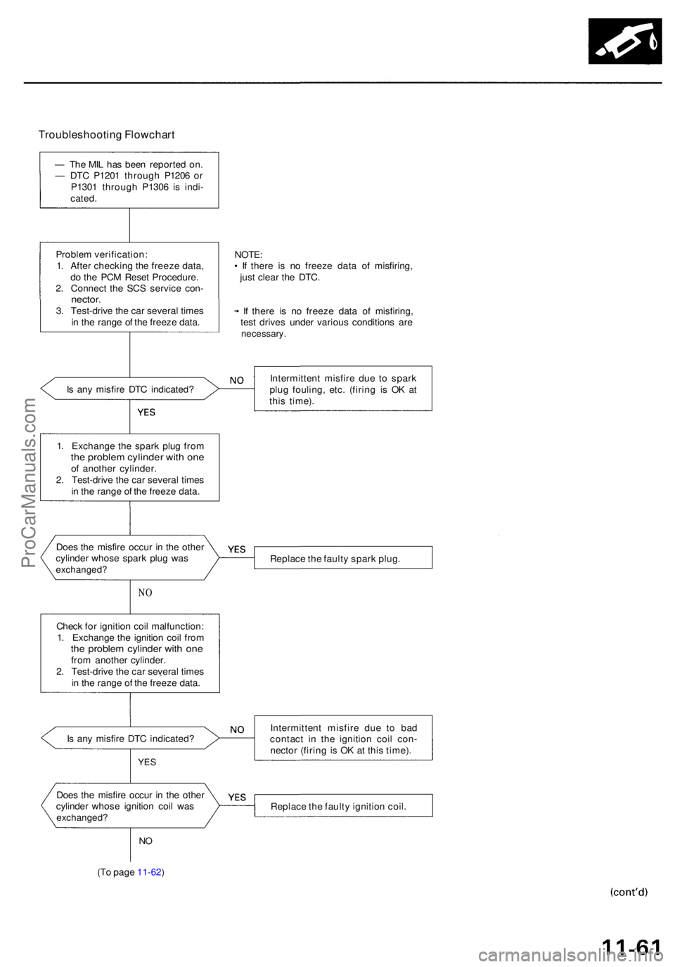
Troubleshooting Flowchar t
— Th e MI L ha s bee n reporte d on .
— DT C P120 1 throug h P120 6 o r
P130 1 throug h P130 6 i s indi -
cated .
Proble m verification :
1 . Afte r checkin g th e freez e data ,
d o th e PC M Rese t Procedure .
2 . Connec t th e SC S servic e con -
nector .3. Test-driv e th e ca r severa l time s
i n th e rang e o f th e freez e data .
I s an y misfir e DT C indicated ?
NO
Chec k fo r ignitio n coi l malfunction :
1 . Exchang e th e ignitio n coi l fro m
the proble m cylinde r wit h on efrom anothe r cylinder .
2 . Test-driv e th e ca r severa l time s
i n th e rang e o f th e freez e data .
I s an y misfir e DT C indicated ?
YES
NO
(T o pag e 11-62 )
NOTE:• I f ther e i s n o freez e dat a o f misfiring ,
jus t clea r th e DTC .
• I f ther e i s n o freez e dat a o f misfiring ,
tes t drive s unde r variou s condition s ar e
necessary .
Intermitten t misfir e du e t o spar k
plu g fouling , etc . (firin g i s O K a t
thi s time) .
Replac e th e fault y spar k plug .
Intermitten t misfir e du e t o ba d
contac t i n th e ignitio n coi l con -
necto r (firin g is O K a t thi s time) .
Replac e th e fault y ignitio n coil .
Doe
s th e misfir e occu r i n th e othe r
cylinde r whos e spar k plu g wa s
exchanged ?
Does th e misfir e occu r i n th e othe r
cylinde r whos e ignitio n coi l wa s
exchanged ?
1. Exchang e th e spar k plu g fro mthe proble m cylinde r wit h on eof anothe r cylinder .
2 . Test-driv e th e ca r severa l time s
i n th e rang e o f th e freez e data .
ProCarManuals.com
Page 152 of 1954
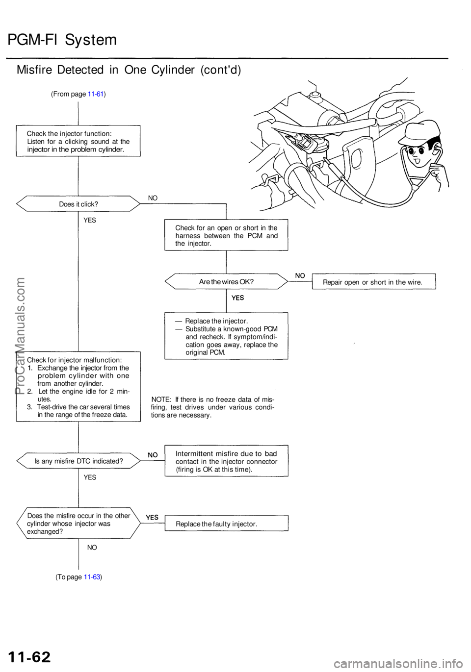
PGM-FI Syste m
Misfire Detecte d i n On e Cylinde r (cont'd )
(From pag e 11-61 )
Chec k th e injecto r function :
Liste n fo r a clickin g soun d a t th e
injecto r i n th e proble m cylinder .
Does it click ?NO
YE SChec k fo r a n ope n o r shor t i n th e
harnes s betwee n th e PC M an d
th e injector .
Are th e wire s OK ?
Chec k fo r injecto r malfunction :1. Exchang e th e injecto r fro m th eproble m cylinde r wit h on efrom anothe r cylinder .
2 . Le t th e engin e idl e fo r 2 min -
utes.3. Test-driv e th e ca r severa l time s
i n th e rang e o f th e freez e data . Repai
r ope n o r shor t i n th e wire .
NOTE : I f ther e i s n o freez e dat a o f mis -
firing , tes t drive s unde r variou s condi -
tion s ar e necessary .
I s an y misfir e DT C indicated ?
YES
Intermitten t misfir e du e t o ba dcontac t i n th e injecto r connecto r
(firin g is O K a t thi s time) .
Doe s th e misfir e occu r i n th e othe r
cylinde r whos e injecto r wa s
exchanged ?Replace th e fault y injector .
NO
(T o pag e 11-63 ) —
Replac e th e injector .
— Substitut e a known-goo d PC M
an d recheck . I f symptom/indi -
catio n goe s away , replac e th e
origina l PCM .
ProCarManuals.com
Page 229 of 1954
Navigation Syste m
Genera l Troubleshootin g Informatio n
General Operatio n
Refer t o th e Acur a Navigatio n Syste m Owner' s manua l
fo r th e navigatio n syste m operatin g procedures .
Anti-theft Featur e
The navigatio n syste m ha s a code d thef t protectio n cir -
cuit . B e sur e t o ge t th e customer' s 4-digi t securit y cod e
numbe r before :
• disconnectin g th e batter y
• disconnectin g th e navigatio n uni t 8 P connecto r
• removin g th e No . 5 6 (7.5A ) fus e fro m th e under-hoo d
fuse/rela y bo x
Afte r service , reconnec t powe r t o th e navigatio n unit ,
an d tur n th e ignitio n switc h O N (II) . Ente r th e 4-digi t
securit y code , the n selec t "Done" .
I f th e cod e canno t b e found , us e th e interactiv e Networ k
( iN ) t o loo k i t up . Yo u wil l nee d th e seria l numbe r fo r
th e navigatio n uni t i n th e trunk . I t i s o n a ta g o n th e
undersid e o f th e unit . Alternatively , yo u ca n vie w th e
seria l numbe r i n on e o f th e Nav i EC U diagnosti c
screens.
When replacin g th e navigatio n unit , b e sur e t o giv e th e
custome r th e ne w anti-thef t securit y code .
Sympto m Diagnosi s
Under som e circumstances , th e navigatio n syste m ma y
behav e in a n inconsisten t manner . Som e customer s ma y
thin k tha t thi s indicate s a proble m when , i n fact , th e
syste m is workin g properly . Kee p th e followin g item s i n
min d whe n interviewin g customer s abou t symptom s
o f th e navigatio n system .
Self-lnertia l Navigatio n Limitation s
When GP S signal s canno t b e receive d (lik e in a tunne l o r
i n a n urba n environmen t o f tal l buildings) , th e syste m is
totall y dependan t o n th e ya w rat e an d spee d senso r t o
positio n th e vehicl e o h th e map . Unde r thes e circum -
stance s smal l error s i n th e ya w rat e an d spee d senso r
ca n accumulat e an d displa y th e vehicl e positio n o n a n
adjacen t street , o r laggin g behin d th e actua l position .
Thi s i s normal , an d usuall y correct s itsel f onc e sate -
llit e receptio n is re-established .
Th e followin g circumstance s ma y cause s vehicl e posi -
tionin g errors . •
Movin g th e vehicl e wit h th e navigatio n syste m o n an d
th e vehicl e stopped , suc h a s b y ferr y o r to w truck , o r i f
th e vehicl e is spu n o n a tur n tabl e
• Tir e slippage , change s i n tir e rollin g diameters , an d
som e drivin g situation s ma y caus e discrepancie s i n
trave l distances . Example s o f thi s include :
- Continuou s tir e slippag e o n a slipper y surfac e
- Drivin g wit h sno w chain s mounte d
-Abnorma l tir e pressur e
- Incorrec t tir e siz e
- Frequen t lan e change s acros s a wid e highwa y
-Continuou s drivin g o n a straigh t o r gentl y curvin g
highwa y
• Tolerance s i n th e syste m an d ma p inaccuracie s some -
times limi t ho w precisel y th e vehicl e positio n i s indi -
cated . Example s o f thi s include :
- Drivin g o n road s no t show n o n th e ma p (ma p match -
in g i s no t possible )
- Drivin g o n a roa d tha t wind s i n on e direction , suc h a s
a loo p bridge , a n interchange , o r a spira l parkin g
garage
-Drivin g o n a roa d wit h a serie s o f shar p hair-pi n
turn s
- Drivin g nea r a gradua l highwa y exi t o r transitio n
- Drivin g o n on e o f tw o close paralle l road s
- Makin g man y 9 0 degre e turn s
Globa l Positionin g Syste m (GPS ) Limitation s
The GP S canno t detec t th e vehicle' s positio n durin g th e
followin g instances :
• Fo r th e firs t 5 to 1 0 minute s afte r reconnectin g th e bat -
ter y (thi s ca n tak e a s lon g a s 4 5 minutes )
• Whe n th e satellit e signal s ar e blocke d b y tal l building ,
mountains , tunnels , larg e trees , o r larg e truck s
• Whe n ther e i s n o satellit e signa l outpu t (Signa l outpu t
i s sometime s stoppe d fo r satellit e servicing )
• Whe n th e satellit e signal s ar e blocke d b y th e operatio n
of som e electroni c aftermarke t accessorie s including ,
but no t limite d t o non-DE M in-das h entertainmen t
unit s (radio , C D players/changers , an d L o Jack ) an d
windo w tintin g abov e th e GP S antenn a
Th e accurac y o f GP S is reduce d durin g thes e instances :
• Whe n onl y tw o satellit e signal s ca n b e receive d (Thre e
satellit e signal s ar e require d fo r accurat e positioning )
• Whe n th e satellit e contro l center s ar e experiencin g
problem s
• Whe n drivin g hea r hig h tensio n powe r lines .
• Whe n drivin g nea r tal l building s tha t reflec t satellit e
signals , creatin g fals e positio n locatio n readings .
• I f electroni c GP S jammin g i s occurrin g eithe r inten -
tionally , o r unintentionally .
• I f loos e item s o r pet s ar e restin g abov e th e antenn a
o n th e rea r shelf .
ProCarManuals.com
Page 244 of 1954
Navigation Unit
The navigation unit calculates the vehicle position and guides you to the destination. The unit performs map matching
correction, GPS correction, and distance tuning. It also controls the menu functions and the DVD-ROM drive, and inter-
prets voice commands. With control of all these items, the navigation unit makes the navigation picture signal, then it
transmits the signal to the display unit and audio driving instructions to the audio unit.
Calculation of Vehicle Position
The navigation unit calculates the vehicle position (the driving direction and the current position) by receiving the direc-
tional change signals from the yaw rate sensor and the travel distance signals from the vehicle speed pulse (VSP) sensor.
Map Matching Tuning
The map matching tuning is accomplished by indicating the vehicle position on the roads on the map. The map data
transmitted from the DVD-ROM is checked against the vehicle position data, and the vehicle position is indicated on the
nearest road. Map matching tuning does not occur when the vehicle travels on a road not shown on the map, or when the
vehicle position is far away from a road on the map.
GPS Tuning
The GPS tuning is accomplished by indicating the vehicle position as the GPS's vehicle position. The navigation unit com-
pares its calculated vehicle position data with the GPS vehicle position data. If there is a large difference between the two,
the indicated vehicle position is adjusted to the GPS vehicle position.
Distance Tuning
The distance tuning reduces the difference between the travel distance signal from the VSP and the distance data on the
map. The navigation unit compares its calculated vehicle position data with the GPS vehicle position data. The navigation
unit then decreases the tuning value when the vehicle position is always ahead of the GPS vehicle position, and it increas-
es the tuning value when the vehicle position is always behind the GPS vehicle position.
Route Guidance
The navigation unit can calculate different routes to a selected destination. You have five options:
• Direct Route - Calculate a route that is the most direct and will take the least tome.
• Easy Route - Calcute a route that minimizes the number of turns needed.
• Minimize Freeways - Calculate a route that avoids freeway travel. If that is not possible, keep the amount of freeway
travel to a minimum.
• Minimize Toll Roads - Calculate a route that avoids, or minimizes travel on toll roads.
• Maximize Freeways - Calculate a route that uses freeways as much as possible.
Audio Guidance
The navigation unit transmits audio driving instructions before entering an intersection or passing a junction.
The audio instructions come through the audio unit and the front speakers.
The front speakers are muted whenever the navigation system is giving guidance commands, and all of the speakers
when the voice control system is being used. When using OnStar, both the audio system and the navigation system are
muted, and the voice control switch (TALK and BACK buttons) is disabled.
DVD-ROM
The map data (including all scale rates) is stored in the DVD-ROM. The map date includes:
• Road distances, road widths, speed limits, traffic regulations, passing time at junction, distances to junctions, and the
driving instructions for audio guidance.
• Latitude and longitude GPS.ProCarManuals.com
Page 262 of 1954
Display day/nigh t mod e doe s no t wor k
Diagnosti c Test : Ca r Statu s
NOTE :
• Alway s chec k th e connector s fo r poo r connection s o r
loos e terminals .
• Befor e troubleshooting , ge t th e navigatio n syste m
anti-thef t codes .
• Afte r troubleshooting , ente r th e navigatio n syste m
anti-thef t codes .
1 . Chang e th e day/nigh t mod e t o "AUTO " unde r Set-up ,
an d recheck .
Doe s the display change to day and night modes?
YES—Th e syste m is O K a t thi s time .
NO—G o to ste p 2 .
2 . G o int o th e Diagnosti c Mod e an d us e diagnosti c th e
"Ca r Status " fo r a n IL L signa l (se e pag e 23-45 ) t o
check .
Is the "ILL" signal OK?
YES—Th e syste m is OK .
NO—Chec k th e IL L + circui t betwee n th e navigatio n
uni t an d tailligh t relay .
System lock s u p constantl y
Diagnostic Test : Uni t Chec k
1. Star t th e engin e an d tur n th e ignitio n switc h OFF ,
the n tur n th e ignitio n switc h O N (II) .
Doe s the system reboot?
YES—Th e syste m is O K a t thi s time .
NO—Chec k th e DV D fo r scratche s o r damag e an d th e
navigatio n uni t fo r wate r damage . I f OK , perfor m al l
o f th e "Uni t check " check s unde r Syste m Diagnosi s
Test (se e pag e 23-43 ).
ProCarManuals.com
Page 275 of 1954
Navigation System
System Diagnosis Mode (cont'd)
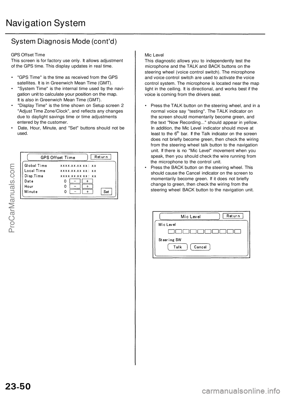
GPS Offset Time
This screen is for factory use only. It allows adjustment
of the GPS time. This display updates in real time.
• "GPS Time" is the time as received from the GPS
satellites. It is in Greenwich Mean Time (GMT).
• "System Time" is the internal time used by the navi-
gation unit to calculate your position on the map.
It is also in Greenwich Mean Time (GMT).
• "Display Time" is the time shown on Setup screen 2
"Adjust Time Zone/Clock", and reflects any changes
due to daylight savings time or time adjustments
entered by the customer.
• Date, Hour, Minute, and "Set" buttons should not be
used.
Mic Level
This diagnostic allows you to independently test the
microphone and the TALK and BACK buttons on the
steering wheel (voice control switch). The microphone
and voice control switch are used to activate the voice
control system. The microphone is located near the map
light in the ceiling. It is directional, and works best if the
voice is coming from the drivers seat.
• Press the TALK button on the steering wheel, and in a
normal voice say "testing". The TALK indicator on
the screen should momentarily become green, and
the text "Now Recording..." should appear in yellow.
In addition, the Mic Level indicator should move at
least to the 6th bar. If the Talk indicator on the screen
does not briefly become green, then check the wiring
from the steering wheel talk button to the navigation
unit. If there is no "Mic Level" movement when you
speak, then you should check the wire running from
the microphone to the control unit.
• Press the BACK button on the steering wheel. This
should cause the Cancel indicator on the screen to
momentarily become green. If it does not briefly
change to green, then check the wiring from the
steering wheel BACK button to the navigation unit.ProCarManuals.com
Page 421 of 1954
Valves, Valv e Spring s an d Valve Seals
Installatio n
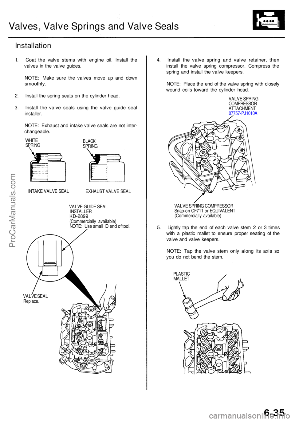
1. Coa t th e valv e stem s wit h engin e oil . Instal l th e
valve s i n th e valv e guides .
NOTE : Mak e sur e th e valve s mov e u p an d dow n
smoothly .
2. Instal l th e sprin g seat s o n th e cylinde r head .
3 . Instal l th e valv e seal s usin g th e valv e guid e sea l
installer .
NOTE : Exhaus t an d intak e valv e seal s ar e no t inter -
changeable .
WHITE
SPRIN GBLACKSPRIN G
INTAK E VALV E SEA L
EXHAUST VALV E SEA L
VALV E GUID E SEA L
INSTALLE RKD-2899(Commerciall y available )NOTE: Us e smal l I D en d o f tool .
VALV E SEA LReplace .
4. Instal l th e valv e sprin g an d valv e retainer , the n
instal l th e valv e sprin g compressor . Compres s th e
sprin g an d instal l th e valv e keepers .
NOTE : Plac e th e en d o f th e valv e sprin g wit h closel y
woun d coil s towar d th e cylinde r head .
VALV E SPRIN GCOMPRESSO RATTACHMENT
0775 7-PJ1010 A
VALV E SPRIN G COMPRESSO R
Snap-o n CF71 1 o r EQUIVALEN T
(Commerciall y available )
5. Lightl y ta p th e en d o f eac h valv e ste m 2 or 3 time s
wit h a plasti c malle t t o ensur e prope r seatin g o f th e
valv e an d valv e keepers .
NOTE : Ta p th e valv e ste m onl y alon g it s axi s s o
yo u d o no t ben d th e stem .
PLASTI CMALLET
ProCarManuals.com
Page 544 of 1954
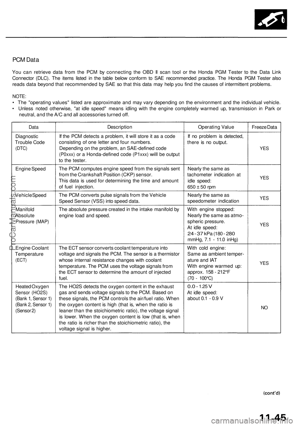
PCM Data
You can retrieve data from the PCM by connecting the OBD II scan tool or the Honda PGM Tester to the Data Link
Connector (DLC). The items listed in the table below conform to SAE recommended practice. The Honda PGM Tester also
reads data beyond that recommended by SAE so that this data may help you find the causes of intermittent problems.
NOTE:
• The "operating values" listed are approximate and may vary depending on the environment and the individual vehicle.
• Unless noted otherwise, "at idle speed" means idling with the engine completely warmed up, transmission in Park or
neutral, and the A/C and all accessories turned off.
Data
Description
Operating Value
Freeze Data
Diagnostic
Trouble Code
(DTC)
If the PCM detects a problem, it will store it as a code
consisting of one letter and four numbers.
Depending on the problem, an SAE-defined code
(P0xxx)
or a
Honda-defined code
(P1xxx)
will
be
output
to the tester.
If no problem is detected,
there is no output.
YES
Engine Speed
The PCM computes engine speed from the signals sent
from the Crankshaft Position (CKP) sensor.
This data is used for determining the time and amount
of fuel injection.
Nearly the same as
tachometer indication at
idle speed:
650 ± 50 rpm
YES
Vehicle Speed
The PCM converts pulse signals from the Vehicle
Speed Sensor (VSS) into speed data.
Nearly the same as
speedometer indication
YES
Manifold
Absolute
Pressure (MAP)
The absolute pressure created in the intake manifold by
engine load and speed.
With engine stopped:
Nearly the same as atmo-
spheric pressure.
At idle speed:
24 - 37
kPa
(180
-
280
mmHg, 7.1 - 11.0 inHg)
YES
Engine Coolant
Temperature
(ECT)
The ECT sensor converts coolant temperature into
voltage and signals the PCM. The sensor is a thermistor
whose internal resistance changes with coolant
temperature. The PCM uses the voltage signals from
the ECT sensor to determine the amount of injected
fuel.
With cold engine:
Same as ambient temper-
ature and IAT
With engine warmed up:
approx. 158 - 212°F
(70 - 100°C)
YES
Heated Oxygen
Sensor (HO2S)
(Bank 1, Sensor 1)
(Bank 2, Sensor 1)
(Sensor 2)
The HO2S detects the oxygen content in the exhaust
gas and sends voltage signals to the PCM. Based on
these signals, the PCM controls the air/fuel ratio. When
the oxygen content is high (that is, when the ratio is
leaner than the stoichiometric ratio), the voltage signal
is lower. When the oxygen content is low (that is, when
the ratio is richer than the stoichiometric ratio), the
voltage signal is higher.
0.0 -
1.25
V
At idle speed:
about 0.1 - 0.9 V
NOProCarManuals.com
Page 579 of 1954
PGM-FI Syste m
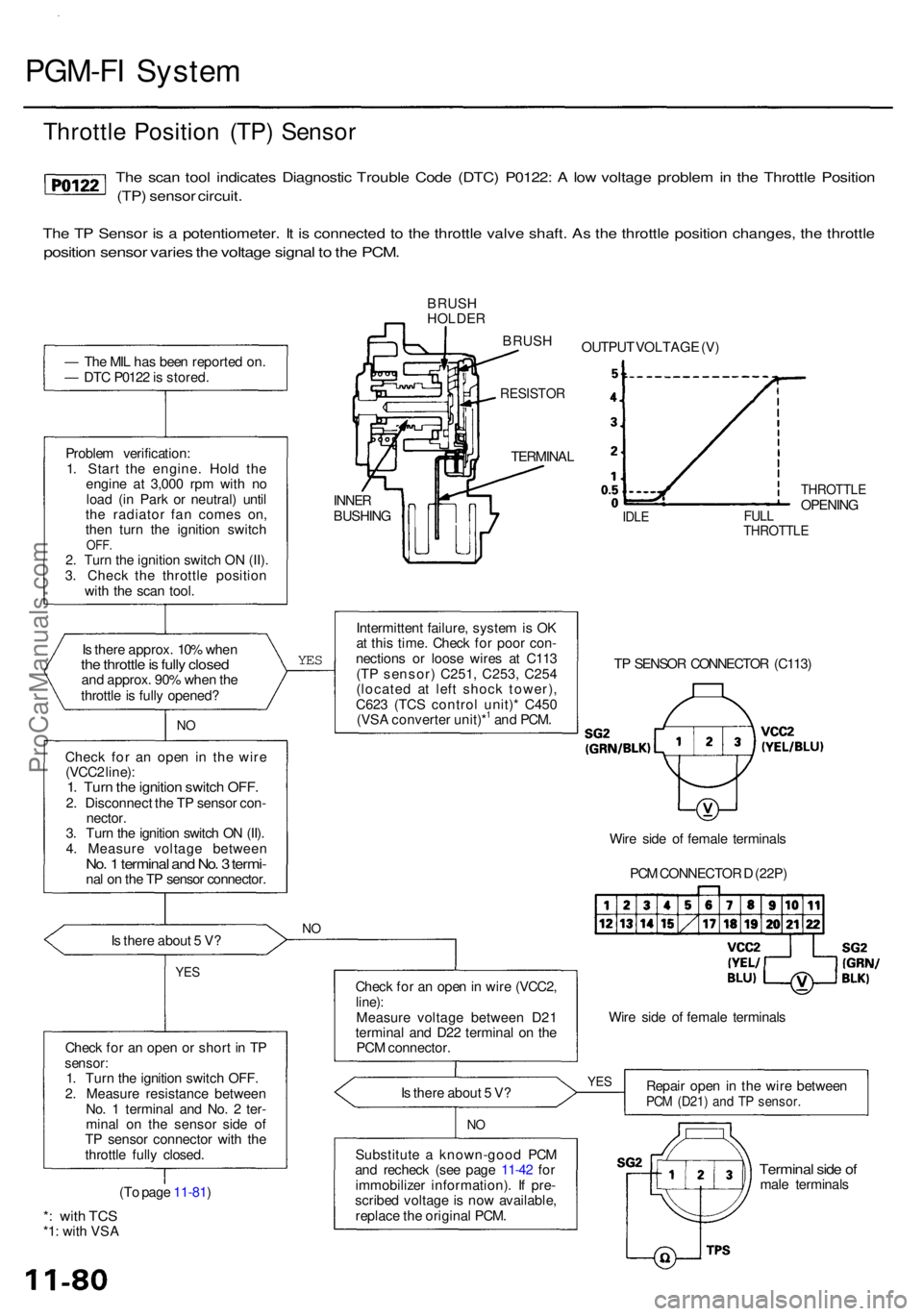
Throttl e Positio n (TP ) Senso r
The sca n too l indicate s Diagnosti c Troubl e Cod e (DTC ) P0122 : A lo w voltag e proble m in th e Throttl e Positio n
(TP) senso r circuit .
The T P Senso r i s a potentiometer . I t i s connecte d t o th e throttl e valv e shaft . A s th e throttl e positio n changes , th e throttl e
position senso r varie s th e voltag e signa l t o th e PCM .
— Th e MI L ha s bee n reporte d on .
— DT C P012 2 is stored .
Proble m verification :
1 . Star t th e engine . Hol d th e
engin e a t 3,00 0 rp m wit h n o
loa d (i n Par k o r neutral ) unti l
th e radiato r fa n come s on ,
the n tur n th e ignitio n switc h
OFF.2. Turn the ignition switch ON (II).3. Chec k th e throttl e positio n
wit h th e sca n tool .
I s ther e approx . 10 % whe n
the throttl e is full y close dand approx . 90 % whe n th e
throttl e is full y opened ?
NO
Chec k fo r a n ope n i n the wire
(VCC 2 line) :
1. Tur n th e ignitio n switc h OFF .2. Disconnec t th e T P senso r con -
nector .
3 . Tur n th e ignitio n switc h O N (II) .
4 . Measur e voltag e betwee n
No. 1 termina l an d No . 3 termi -nal o n th e T P senso r connector . BRUS
H
HOLDE R
BRUS H
RESISTO R
YES
Is ther e abou t 5 V ?NO
YE S
Chec k fo r a n ope n o r shor t i n T Psensor :1. Tur n th e ignitio n switc h OFF .
2 . Measur e resistanc e betwee n
No . 1 termina l an d No . 2 ter -
mina l o n th e senso r sid e o f
T P senso r connecto r wit h th e
throttl e full y closed .
(T o pag e 11-81 )
*: wit h TC S*1: wit h VS A TERMINA
L
INNERBUSHIN GIDLEFUL LTHROTTL E
THROTTLEOPENING
Intermitten t failure , syste m is O K
a t thi s time . Chec k fo r poo r con -
nection s o r loos e wire s a t C11 3
(T P sensor ) C251 , C253 , C25 4
(locate d a t lef t shoc k tower) ,
C62 3 (TC S contro l unit) * C45 0
(VS A converte r unit)*
1 an d PCM . T
P SENSO R CONNECTO R (C113 )
Wir e sid e o f femal e terminal s
Chec k fo r a n ope n in wir e (VCC2 ,
line):Measur e voltag e betwee n D2 1
termina l an d D2 2 termina l o n th e
PC M connector . Wir
e sid e o f femal e terminal s
I s ther e abou t 5 V ? Repai
r ope n in th e wir e betwee n
PCM (D21 ) an d T P sensor .
NO
Substitut e a known-goo d PC M
an d rechec k (se e pag e 11-42 fo r
immobilize r information) . I f pre -
scribe d voltag e is no w available ,
replac e th e origina l PCM .Termina l sid e o fmal e terminal s
YES
PCM CONNECTO R D (22P )
OUTPU
T VOLTAG E (V )
ProCarManuals.com