fuel cap ACURA RL KA9 1996 Service Repair Manual
[x] Cancel search | Manufacturer: ACURA, Model Year: 1996, Model line: RL KA9, Model: ACURA RL KA9 1996Pages: 1954, PDF Size: 61.44 MB
Page 178 of 1954
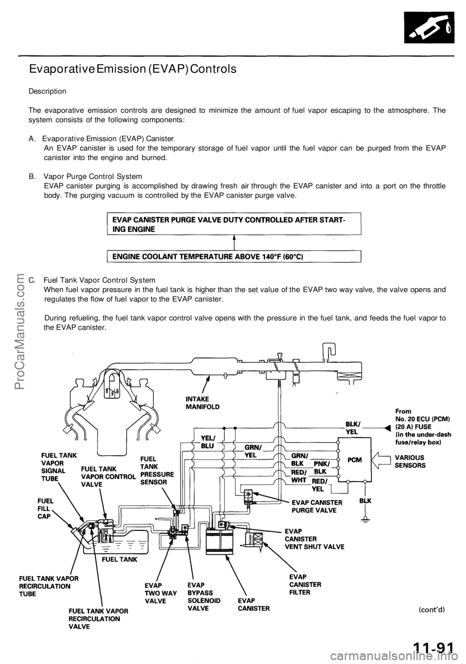
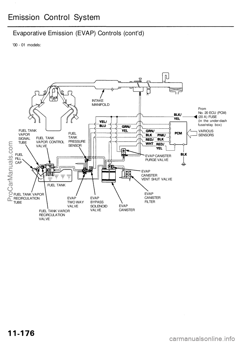
Evaporative Emission (EVAP) Controls
Description
The evaporative emission controls are designed to minimize the amount of fuel vapor escaping to the atmosphere. The
system consists of the following components:
A. Evaporative Emission (EVAP) Canister
An EVAP canister is used for the temporary storage of fuel vapor until the fuel vapor can be purged from the EVAP
canister into the engine and burned.
B. Vapor Purge Control System
EVAP canister purging is accomplished by drawing fresh air through the EVAP canister and into a port on the throttle
body. The purging vacuum is controlled by the EVAP canister purge valve.
C. Fuel Tank Vapor Control System
When fuel vapor pressure in the fuel tank is higher than the set value of the EVAP two way valve, the valve opens and
regulates the flow of fuel vapor to the EVAP canister.
During refueling, the fuel tank vapor control valve opens with the pressure in the fuel tank, and feeds the fuel vapor to
the EVAP canister.ProCarManuals.com
Page 187 of 1954
Emission Contro l Syste m
Evaporativ e Emissio n (EVAP ) Control s (cont'd )
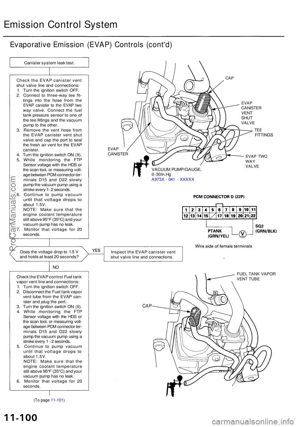
Canister syste m lea k test .
Chec k th e EVA P caniste r ven t
shu t valv e lin e an d connections :
1 . Tur n th e ignitio n switc h OFF .
2 . Connec t t o three-wa y te e fit -
ting s int o th e hos e fro m th e
EVA P caniste r t o th e EVA P tw oway valve . Connec t th e fue l
tan k pressur e senso r t o on e o f
th e te e fitting s an d th e vacuu m
pum p to th e other .
3 . Remov e th e ven t hos e fro m
th e EVA P caniste r ven t shu t
valv e an d ca p th e por t t o sea l
th e fres h ai r ven t fo r th e EVA P
canister .4. Tur n th e ignitio n switc h O N (II) .
5 . Whil e monitorin g th e FT P
Senso r voltag e wit h th e HD S o r
th e sca n tool , o r measurin g volt -
ag e betwee n PC M connecto r ter -
minal s D1 5 an d D2 2 slowl y
pum p th e vacuu m pum p usin g a
strok e ever y 1- 2 seconds .
6 . Continu e t o pum p vacuu m
until tha t voltag e drop s t oabou t 1.5V .
NOTE : Mak e sur e tha t th e
engin e coolan t temperatur e
stil l abov e 95° F (35°C ) an d you r
vacuu m pum p ha s n o leak .
7 . Monito r tha t voltag e fo r 2 0
seconds .
Doe s th e voltag e dro p to 1. 5 V
an d hold s a t leas t 2 0 seconds ?
NO
Chec k th e EVA P contro l Fue l tan k
vapo r ven t lin e an d connections :
1 . Tur n th e ignitio n switc h OFF .
2 . Disconnec t th e Fue l tan k vapo r
ven t tub e fro m th e EVA P can -
iste r an d plu g th e port .
3 . Tur n th e ignitio n switc h O N (II) .
4 . Whil e monitorin g th e FT P
Senso r voltag e wit h th e HD S o r
th e sca n tool , o r measurin g volt -
ag e betwee n PC M connecto r ter -
minal s D1 5 an d D2 2 slowl y
pum p th e vacuu m pum p usin g a
strok e ever y 1 - 2 seconds .
5 . Continu e t o pum p vacuu m
until tha t voltag e drop s t oabou t 1.5V .
NOTE : Mak e sur e tha t th e
engin e coolan t temperatur e
stil l abov e 95° F (35°C ) an d you r
vacuu m pum p ha s n o leak .
6 . Monito r tha t voltag e fo r 2 0
seconds .
CAP
EVA PCANISTE R
EVAPCANISTE RVENTSHU TVALV E
VACUU M PUMP/GAUGE ,
0 - 3 0 In.H g
A973 X - 04 1 - XXXX X
TEEFITTING S
EVAP TW OWAYVALV E
Inspec t th e EVA P caniste r ven t
shu t valv e lin e an d connections .
FUEL TANK VAPOR
VENT TUBE
CA P
(To page 11-101)
ProCarManuals.com
Page 506 of 1954
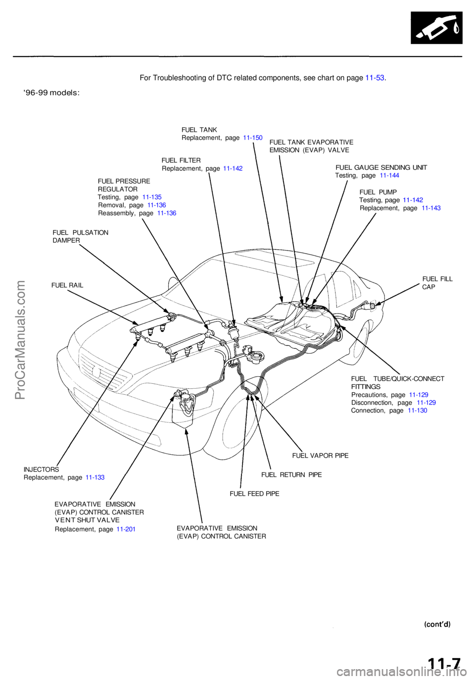
'96-99 models :
FUEL FILTE R
Replacement , pag e 11-14 2
FUE L PRESSUR E
REGULATO RTesting, pag e 11-13 5
Removal , pag e 11-13 6
Reassembly , pag e 11-13 6
FUEL GAUG E SENDIN G UNI TTesting , pag e 11-14 4
FUE L PUM P
Testing , pag e 11-14 2Replacement , pag e 11-14 3
FUE L PULSATIO N
DAMPE R
FUE L RAI L FUE
L FIL L
CAP
FUE L TUBE/QUICK-CONNEC TFITTINGSPrecautions , pag e 11-12 9
Disconnection , pag e 11-12 9
Connection , pag e 11-13 0
INJECTOR S
Replacement , pag e 11-133
EVAPORATIV E EMISSIO N
(EVAP ) CONTRO L CANISTE R
VENT SHU T VALV E
Replacement , pag e 11-20 1 EVAPORATIV
E EMISSIO N
(EVAP ) CONTRO L CANISTE R
FUE
L FEE D PIP E
FUE
L RETUR N PIP E
FUE
L VAPO R PIP E
FUE
L TAN K
Replacement , pag e 11-15 0
FUE L TAN K EVAPORATIV E
EMISSIO N (EVAP ) VALV E
For Troubleshooting of DTC related components, see chart on page 11-53.
ProCarManuals.com
Page 507 of 1954
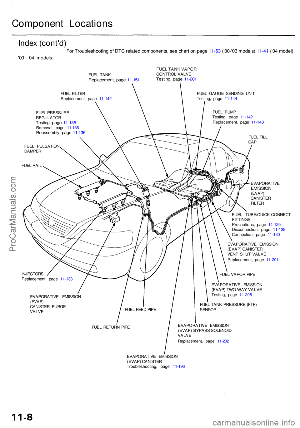
Component Location s
Index (cont'd )
FUEL TAN KReplacement , pag e 11-15 1
FUEL TAN K VAPO RCONTROL VALVETesting, pag e 11-20 1
FUEL FILTE R
Replacement , pag e 11-14 2
FUE L PRESSUR E
REGULATO R
Testing, pag e 11-13 5Removal , pag e 11-13 6Reassembly , pag e 11-13 6
FUEL PULSATIO N
DAMPE R
FUE L RAI L
INJECTOR S
Replacement , pag e 11-13 3
EVAPORATIV E EMISSIO N
(EVAP)CANISTE R PURG E
VALV E FUE
L GAUG E SENDIN G UNI T
Testing , pag e 11-14 4
FUE L PUM P
Testing , pag e 11-14 2
Replacement , pag e 11-14 3
FUE L FIL L
CAP
EVAPORATIV EEMISSION(EVAP)CANISTE RFILTER
FUEL TUBE/QUICK-CONNEC TFITTINGSPrecautions , pag e 11-12 9
Disconnection , pag e 11-12 9
Connection , pag e 11-13 0
EVAPORATIV E EMISSIO N
(EVAP ) CANISTE R
VEN T SHU T VALV E
Replacement , pag e 11-20 1
FUE L VAPO R PIP E
EVAPORATIV E EMISSIO N
(EVAP ) TW O WA Y VALV E
Testing , pag e 11-20 5
FUE L TAN K PRESSUR E (FTP )
SENSO R
FUE L RETUR N PIP E EVAPORATIV
E EMISSIO N
(EVAP ) BYPAS S SOLENOI D
VALV E
Replacement , pag e 11-20 2
EVAPORATIV E EMISSIO N
(EVAP ) CANISTE R
Troubleshooting , pag e 11-19 6
FUE
L FEE D PIP E
'00 - 0 4 models :
For Troubleshooting of DTC related components, see chart on page 11-53 ('00-'03 models) 11-41 ('04 model).
ProCarManuals.com
Page 560 of 1954
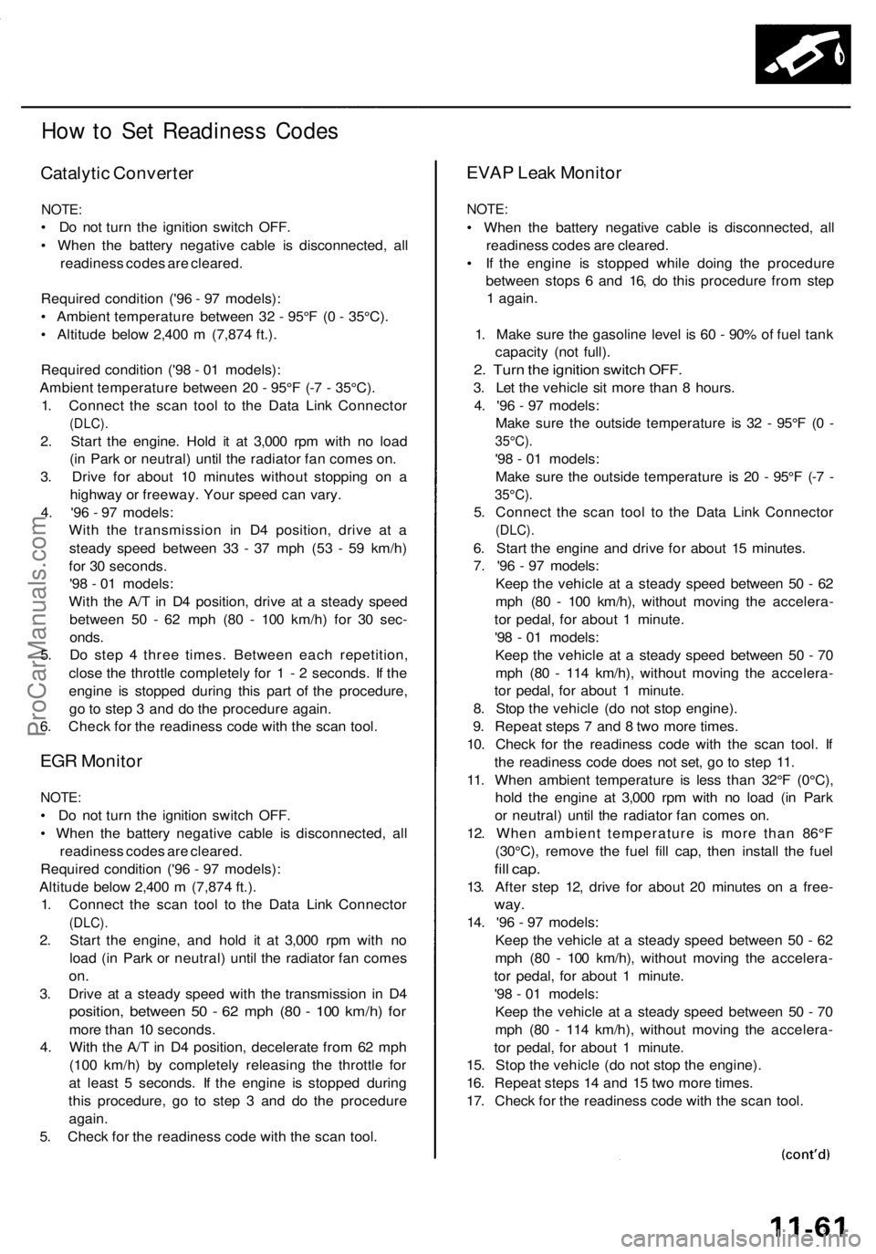
How to Set Readiness Codes
Catalytic Converter
NOTE:
• Do not turn the ignition switch OFF.
• When the battery negative cable is disconnected, all
readiness codes are cleared.
Required condition ('96 - 97 models):
• Ambient temperature between 32 - 95°F (0 - 35°C).
• Altitude below 2,400 m (7,874 ft.).
Required condition ('98 - 01 models):
Ambient temperature between 20 - 95°F (-7 - 35°C).
1. Connect the scan tool to the Data Link Connector
(DLC).
2. Start the engine. Hold it at 3,000 rpm with no load
(in Park or neutral) until the radiator fan comes on.
3. Drive for about 10 minutes without stopping on a
highway or freeway. Your speed can vary.
4. '96 - 97 models:
With the transmission in D4 position, drive at a
steady speed between 33 - 37 mph (53 - 59 km/h)
for 30 seconds.
'98 - 01 models:
With the A/T in D4 position, drive at a steady speed
between 50 - 62 mph (80 - 100 km/h) for 30 sec-
onds.
5. Do step 4 three times. Between each repetition,
close the throttle completely for 1 - 2 seconds. If the
engine is stopped during this part of the procedure,
go to step 3 and do the procedure again.
6. Check for the readiness code with the scan tool.
EGR Monitor
NOTE:
• Do not turn the ignition switch OFF.
• When the battery negative cable is disconnected, all
readiness codes are cleared.
Required condition ('96 - 97 models):
Altitude below 2,400 m (7,874 ft.).
1. Connect the scan tool to the Data Link Connector
(DLC).
2. Start the engine, and hold it at 3,000 rpm with no
load (in Park or neutral) until the radiator fan comes
on.
3. Drive at a steady speed with the transmission in D4
position, between 50 - 62 mph (80 - 100 km/h) for
more than 10 seconds.
4. With the A/T in D4 position, decelerate from 62 mph
(100 km/h) by completely releasing the throttle for
at least 5 seconds. If the engine is stopped during
this procedure, go to step 3 and do the procedure
again.
5. Check for the readiness code with the scan tool.
EVAP Leak Monitor
NOTE:
• When the battery negative cable is disconnected, all
readiness codes are cleared.
• If the engine is stopped while doing the procedure
between stops 6 and 16, do this procedure from step
1 again.
1. Make sure the gasoline level is 60 - 90% of fuel tank
capacity (not full).
2. Turn the ignition switch OFF.
3. Let the vehicle sit more than 8 hours.
4. '96 - 97 models:
Make sure the outside temperature is 32 - 95°F (0 -
35°C).
'98 - 01 models:
Make sure the outside temperature is 20 - 95°F (-7 -
35°C).
5. Connect the scan tool to the Data Link Connector
(DLC).
6. Start the engine and drive for about 15 minutes.
7. '96 - 97 models:
Keep the vehicle at a steady speed between 50 - 62
mph (80 - 100 km/h), without moving the accelera-
tor pedal, for about 1 minute.
'98 - 01 models:
Keep the vehicle at a steady speed between 50 - 70
mph (80 - 114 km/h), without moving the accelera-
tor pedal, for about 1 minute.
8. Stop the vehicle (do not stop engine).
9. Repeat steps 7 and 8 two more times.
10. Check for the readiness code with the scan tool. If
the readiness code does not set, go to step 11.
11. When ambient temperature is less than 32°F (0°C),
hold the engine at 3,000 rpm with no load (in Park
or neutral) until the radiator fan comes on.
12. When ambient temperature is more than 86°F
(30°C), remove the fuel fill cap, then install the fuel
fill cap.
13. After step 12, drive for about 20 minutes on a free-
way.
14. '96 - 97 models:
Keep the vehicle at a steady speed between 50 - 62
mph (80 - 100 km/h), without moving the accelera-
tor pedal, for about 1 minute.
'98 - 01 models:
Keep the vehicle at a steady speed between 50 - 70
mph (80 - 114 km/h), without moving the accelera-
tor pedal, for about 1 minute.
15. Stop the vehicle (do not stop the engine).
16. Repeat steps 14 and 15 two more times.
17. Check for the readiness code with the scan tool.ProCarManuals.com
Page 632 of 1954
Fuel Suppl y Syste m
System Descriptio n
The fue l suppl y syste m consist s o f a fue l tank , in-tan k
high-pressur e fue l pump , PGM-F I mai n relay , fue l filter ,
fue l pressur e regulator , fue l pressur e regulato r contro l
solenoi d valve , injectors , an d fue l deliver y an d retur n
lines . Thi s syste m deliver s pressure-regulate d fue l t o th e
injector s an d cut s th e fue l deliver y whe n th e engin e i s
no t running .
Fuel Pressur e
Relieving
Befor e disconnectin g fue l pipe s o r hoses , releas e pres -
sur e fro m th e syste m b y loosenin g th e servic e bol t o n
top o f th e fue l filter .
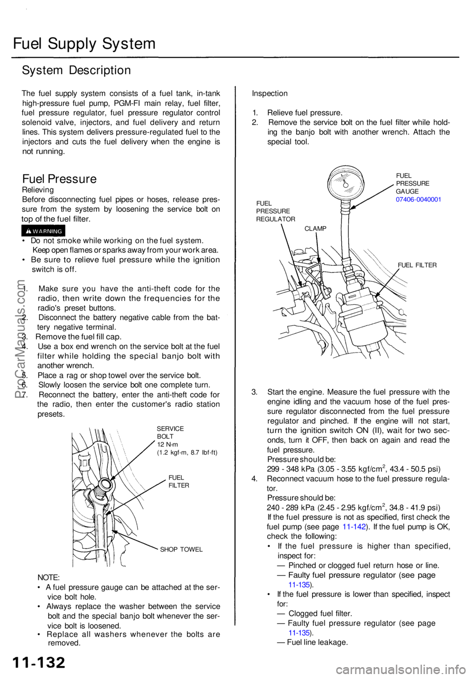
SERVIC E
BOL T
12 N- m(1.2 kgf-m , 8. 7 Ibf-ft )
FUE L
FILTE R
SHOP TOWE L
NOTE:
• A fue l pressur e gaug e can be attache d a t th e ser -
vic e bol t hole .
• Alway s replac e th e washe r betwee n th e servic e
bol t an d th e specia l banj o bol t wheneve r th e ser -
vic e bol t i s loosened .
• Replac e al l washer s wheneve r th e bolt s ar e
removed . Inspectio
n
1 . Reliev e fue l pressure .
2 . Remov e th e servic e bol t o n th e fue l filte r whil e hold -
in g th e banj o bol t wit h anothe r wrench . Attac h th e
specia l tool .
FUEL FILTE R
3. Star t th e engine . Measur e th e fue l pressur e wit h th e
engin e idlin g an d th e vacuu m hos e o f th e fue l pres -
sur e regulato r disconnecte d fro m th e fue l pressur e
regulato r an d pinched . I f th e engin e wil l no t start ,
turn th e ignitio n switc h O N (II) , wai t fo r tw o sec -
onds , tur n i t OFF , the n bac k o n agai n an d rea d th e
fue l pressure .
Pressur e shoul d be :
29 9 - 34 8 kP a (3.0 5 - 3.5 5 kgf/cm
2, 43. 4 - 50. 5 psi )
4 . Reconnec t vacuu m hos e to th e fue l pressur e regula -
tor.
Pressur e shoul d be :
24 0 - 28 9 kP a (2.4 5 - 2.9 5 kgf/cm2, 34. 8 - 41. 9 psi )
I f th e fue l pressur e i s no t a s specified , firs t chec k th e
fue l pum p (se e pag e 11-142 ). I f th e fue l pum p is OK ,
chec k th e following :
• I f th e fue l pressur e i s highe r tha n specified ,
inspec t for :
— Pinche d o r clogge d fue l retur n hos e o r line .
— Fault y fue l pressur e regulato r (se e pag e
11-135 ).
• I f th e fue l pressur e i s lowe r tha n specified , inspec t
for:
— Clogge d fue l filter .
— Fault y fue l pressur e regulato r (se e pag e
11-135 ).
— Fue l lin e leakage .
1
. Mak e sur e yo u hav e th e anti-thef t cod e fo r th e
radio , the n writ e dow n th e frequencie s fo r th e
radio' s prese t buttons .
2 . Disconnec t th e batter y negativ e cabl e fro m th e bat -
ter y negativ e terminal .
3. Remov e th e fue l fil l cap .
4. Us e a bo x en d wrenc h o n th e servic e bol t a t th e fue l
filte r whil e holdin g th e specia l banj o bol t wit h
anothe r wrench .
5. Plac e a ra g o r sho p towe l ove r th e servic e bolt .
6 . Slowl y loose n th e servic e bol t on e complet e turn .
7 . Reconnec t th e battery , ente r th e anti-thef t cod e fo r
th e radio , the n ente r th e customer' s radi o statio n
presets .
•
D o no t smok e whil e workin g o n th e fue l system .
Kee p ope n flame s o r spark s awa y fro m you r wor k area .
• B e sur e t o reliev e fue l pressur e whil e th e ignitio n
switch is off .
CLAM P
FUE
L
PRESSUR E
REGULATO R FUE
L
PRESSUR E
GAUG E
07406-004000 1
ProCarManuals.com
Page 643 of 1954
Fuel Suppl y Syste m
Fuel Pum p
Testin g
Do no t smok e durin g th e test . Kee p ope n
flam e awa y fro m you r wor k area .
I f yo u suspec t a proble m wit h th e fue l pump , chec k tha t
th e fue l pum p actuall y runs ; whe n it i s ON , yo u wil l hea r
som e nois e i f yo u hol d you r ea r t o th e fue l fil l por t wit h
th e fue l fil l cap removed . Th e fue l pum p shoul d ru n fo r 2
second s whe n ignitio n switc h i s firs t turne d on . I f th e
fue l pum p doe s no t mak e noise , chec k a s follows :
1 . Remov e th e rea r sea t cushio n (se e sectio n 20 ).
2 . Disconnec t th e 10 P connector .
CAUTION :
Be sur e to tur n the ignitio n switch OFF
befor e disconnectin g th e wires .
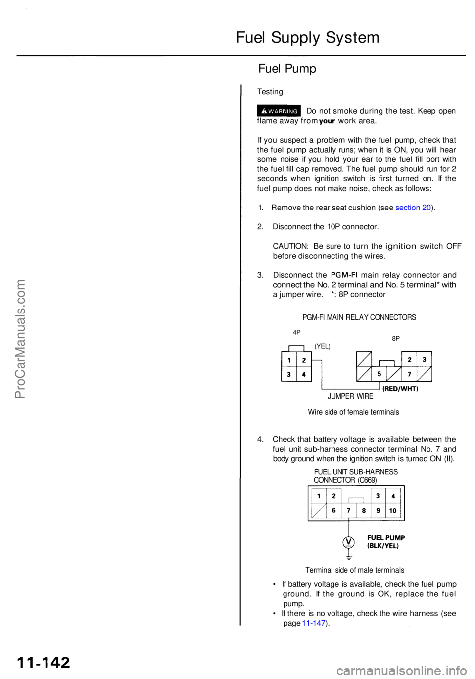
3. Disconnec t th e PGM-F I main rela y connecto r an d
connec t th e No . 2 termina l an d No . 5 terminal * wit h
a jumpe r wire . * : 8 P connecto r
PGM-FI MAI N RELA Y CONNECTOR S
4P8P(YEL )
JUMPE R WIR E
Wire sid e o f femal e terminal s
4. Chec k tha t batter y voltag e i s availabl e betwee n th e
fue l uni t sub-harnes s connecto r termina l No . 7 an d
bod y groun d whe n th e ignitio n switc h is turne d O N (II) .
FUE L UNI T SUB-HARNES SCONNECTOR (C669 )
Termina l sid e o f mal e terminal s
• I f batter y voltag e is available , chec k th e fue l pum p
ground . I f th e groun d i s OK , replac e th e fue l
pump .
• I f ther e is n o voltage , chec k th e wir e harnes s (se e
pag e 11-147 ).
ProCarManuals.com
Page 679 of 1954
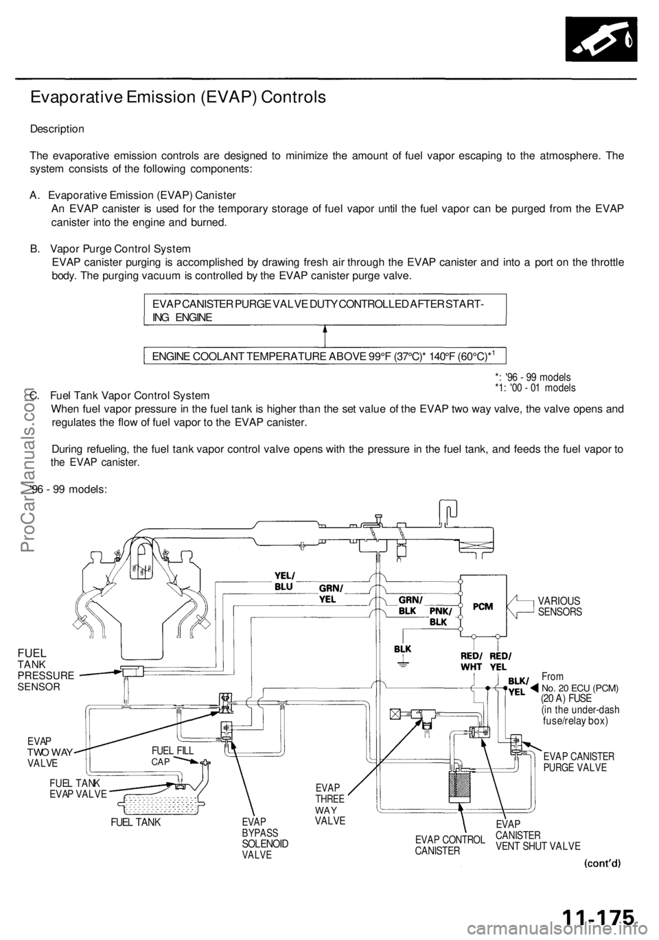
Evaporative Emissio n (EVAP ) Control s
Descriptio n
Th e evaporativ e emissio n control s ar e designe d t o minimiz e th e amoun t o f fue l vapo r escapin g t o th e atmosphere . Th e
syste m consist s o f th e followin g components :
A . Evaporativ e Emissio n (EVAP ) Caniste r
A n EVA P caniste r i s use d fo r th e temporar y storag e o f fue l vapo r unti l th e fue l vapo r can be purge d fro m th e EVA P
caniste r int o th e engin e an d burned .
B . Vapo r Purg e Contro l Syste m
EVA P caniste r purgin g is accomplishe d b y drawin g fres h ai r throug h th e EVA P caniste r an d int o a por t o n th e throttl e
body . Th e purgin g vacuu m is controlle d b y th e EVA P caniste r purg e valve .
EVA P CANISTE R PURG E VALV E DUT Y CONTROLLE D AFTE R START -
IN G ENGIN E
*: '9 6 - 9 9 model s*1: '0 0 - 0 1 model sC. Fue l Tan k Vapo r Contro l Syste m
Whe n fue l vapo r pressur e in th e fue l tan k is highe r tha n th e se t valu e o f th e EVA P tw o wa y valve , th e valv e open s an d
regulate s th e flo w o f fue l vapo r t o th e EVA P canister .
Durin g refueling , th e fue l tan k vapo r contro l valv e open s wit h th e pressur e in th e fue l tank , an d feed s th e fue l vapo r t o
th e EVA P canister .
'96 - 9 9 models :
FUELTANKPRESSURESENSOR
EVAPTWO WAYVALVE
FUEL TANKEVAP VALVE
FUEL TAN K
EVAP CANISTE RPURGE VALV E
EVAPBYPAS SSOLENOI DVALVE
EVAPCANISTE RVENT SHU T VALV EEVAP CONTRO LCANISTER
EVAPTHRE EWAYVALV E
FUEL FIL LCAP
Fro mNo. 2 0 EC U (PCM )(20 A ) FUS E(in th e under-das hfuse/relay box )
VARIOU SSENSOR S
ENGINE COOLAN T TEMPERATUR E ABOV E 99° F (37°C) * 140° F (60°C)*1
ProCarManuals.com
Page 680 of 1954
Emission Control System
Evaporative Emission (EVAP) Controls (cont'd)
'00 - 01 models:
From
No. 20 ECU
(PCM)
(20 A) FUSE
(in the under-dash
fuse/relay box)
FUEL TANK VAPOR
RECIRCULATION
TUBE
EVAP
BYPASS
SOLENOID
VALVE
EVAP
CANISTER
FILTER
EVAP
CANISTER
FUEL TANK VAROR
RECIRCULATION
VALVE
EVAP
TWO WAY
VALVE
FUEL TANK
EVAP
CANISTER
VENT SHUT VALVE
EVAP CANISTER
PURGE VALVE
VARIOUS
SENSORS
INTAKE
MANIFOLD
FUEL
TANK
PRESSURE
SENSOR
FUEL TANK
VAPOR CONTROL
VALVE
FUEL
FILL
CAP
FUEL TANK
VAPOR
SIGNAL
TUBEProCarManuals.com
Page 682 of 1954
Emission Contro l Syste m
Evaporativ e Emissio n (EVAP ) Control s (cont'd )
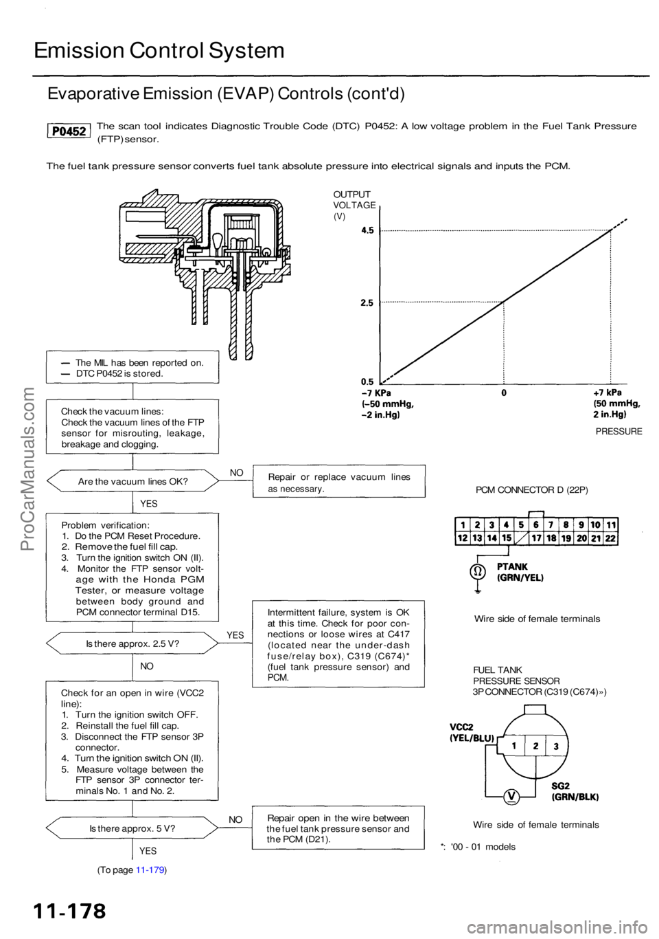
The sca n too l indicate s Diagnosti c Troubl e Cod e (DTC ) P0452 : A lo w voltag e proble m in th e Fue l Tan k Pressur e
(FTP) sensor .
The fue l tan k pressur e senso r convert s fue l tan k absolut e pressur e int o electrica l signal s an d input s th e PCM .
OUTPU TVOLTAG E(V)
Th e MI L ha s bee n reporte d on .
DT C P045 2 is stored .
Chec k th e vacuu m lines :
Chec k th e vacuu m line s o f th e FT P
senso r fo r misrouting , leakage ,
breakag e an d clogging .
Ar e th e vacuu m line s OK ?
YES
Proble m verification :
1 . D o th e PC M Rese t Procedure .
2. Remov e th e fue l fil l cap .3. Tur n th e ignitio n switc h O N (II) .
4 . Monito r th e FT P sensor volt-
age wit h th e Hond a PG MTester , o r measur e voltag ebetwee n bod y groun d an d
PC M connecto r termina l D15 .
I s ther e approx . 2. 5 V ?
NO
Chec k fo r a n ope n in wir e (VCC 2line):1. Tur n th e ignitio n switc h OFF .
2 . Reinstal l th e fue l fil l cap .
3 . Disconnec t th e FT P senso r 3 P
connector .
4. Tur n th e ignitio n switc h O N (II) .5. Measur e voltag e betwee n th e
FT P senso r 3 P connecto r ter -
minal s No . 1 an d No . 2 .
I s ther e approx . 5 V ?
YE S
Repai r o r replac e vacuu m line sas necessary .
Intermittent failure , syste m is O K
a t thi s time . Chec k fo r poo r con -
nection s o r loos e wire s a t C41 7
(locate d nea r th e under-das h
fuse/rela y box) , C31 9 (C674) *
(fue l tan k pressur e sensor ) an d
PCM .
Repai r ope n in th e wir e betwee nthe fue l tan k pressur e senso r an d
th e PC M (D21) .
PRESSUR E
PCM CONNECTO R D (22P )
Wire sid e o f femal e terminal s
FUEL TAN KPRESSUR E SENSO R3P CONNECTO R (C31 9 (C674)» )
Wir e sid e o f femal e terminal s
* : '0 0 - 0 1 model s
(T o pag e 11-179 )
YES
NO
N O
ProCarManuals.com