fuse box location ACURA RL KA9 1996 Service Repair Manual
[x] Cancel search | Manufacturer: ACURA, Model Year: 1996, Model line: RL KA9, Model: ACURA RL KA9 1996Pages: 1954, PDF Size: 61.44 MB
Page 28 of 1954
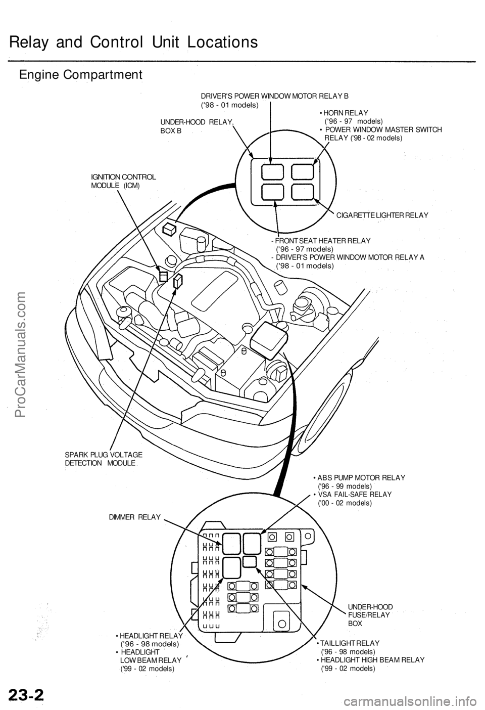
Relay an d Contro l Uni t Location s
Engine Compartmen t
UNDER-HOOD RELAY ,BOX B
IGNITIO N CONTRO LMODULE (ICM )
CIGARETTE LIGHTE R RELA Y
- FRON T SEA T HEATE R RELA Y
('96 - 9 7 models )- DRIVER' S POWE R WINDO W MOTO R RELA Y A('98 - 0 1 models )
• HOR N RELA Y
('96 - 9 7 models )
• POWE R WINDO W MASTE R SWITC H
RELA Y ('9 8 - 0 2 models )
SPAR K PLU G VOLTAG E
DETECTIO N MODUL E
• HEADLIGH T RELA Y
('96 - 9 8 models )• HEADLIGH T
LO W BEA M RELA Y
('9 9 - 0 2 models ) •
TAILLIGH T RELA Y
('9 6 - 9 8 models )
• HEADLIGH T HIG H BEA M RELA Y
('9 9 - 0 2 models )
DIMME
R RELA Y
UNDER-HOOD
FUSE/RELAYBOX
DRIVER' S POWE R WINDO W MOTO R RELA Y B('98 - 0 1 models )
• AB S PUM P MOTO R RELA Y
('9 6 - 9 9 models )
• VS A FAIL-SAF E RELA Y('00 - 0 2 models )
ProCarManuals.com
Page 34 of 1954
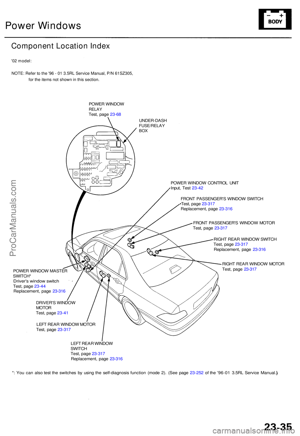
Power Windows
Component Location Index
'02 model:NOTE: Refer to the '96 - 01 3.5RL Service Manual, P/N 61SZ305, for the items not shown in this section.
POWER WINDO WRELAYTest, pag e 23-6 8
UNDER-DAS HFUSE/RELAYBOX
POWE R WINDO W MASTE R
SWITCH *
Driver's windo w switc hTest, pag e 23-4 4
Replacement , pag e 23-31 6
DRIVER' S WINDO W
MOTO R
Test , pag e 23-4 1
LEF T REA R WINDO W MOTO R
Test , pag e 23-31 7 POWE
R WINDO W CONTRO L UNI T
Input , Tes t 23-4 2
FRON T PASSENGER' S WINDO W SWITC H
•Test , pag e 23-31 7
Replacement , pag e 23-31 6
FRON T PASSENGER' S WINDO W MOTO R
Test , pag e 23-31 7
RIGH T REA R WINDO W SWITC H
Test , pag e 23-31 7
Replacement , pag e 23-31 6
RIGH T REA R WINDO W MOTO R
Test , pag e 23-31 7
LEF T REA R WINDO W
SWITC H
Test , pag e 23-31 7
Replacement , pag e 23-31 6
* : Yo u ca n als o tes t th e switche s b y usin g th e self-diagnosi s functio n (mod e 2) . (Se e pag e 23-25 2 o f th e '96-0 1 3.5R L Servic e Manual. ]
ProCarManuals.com
Page 1081 of 1954
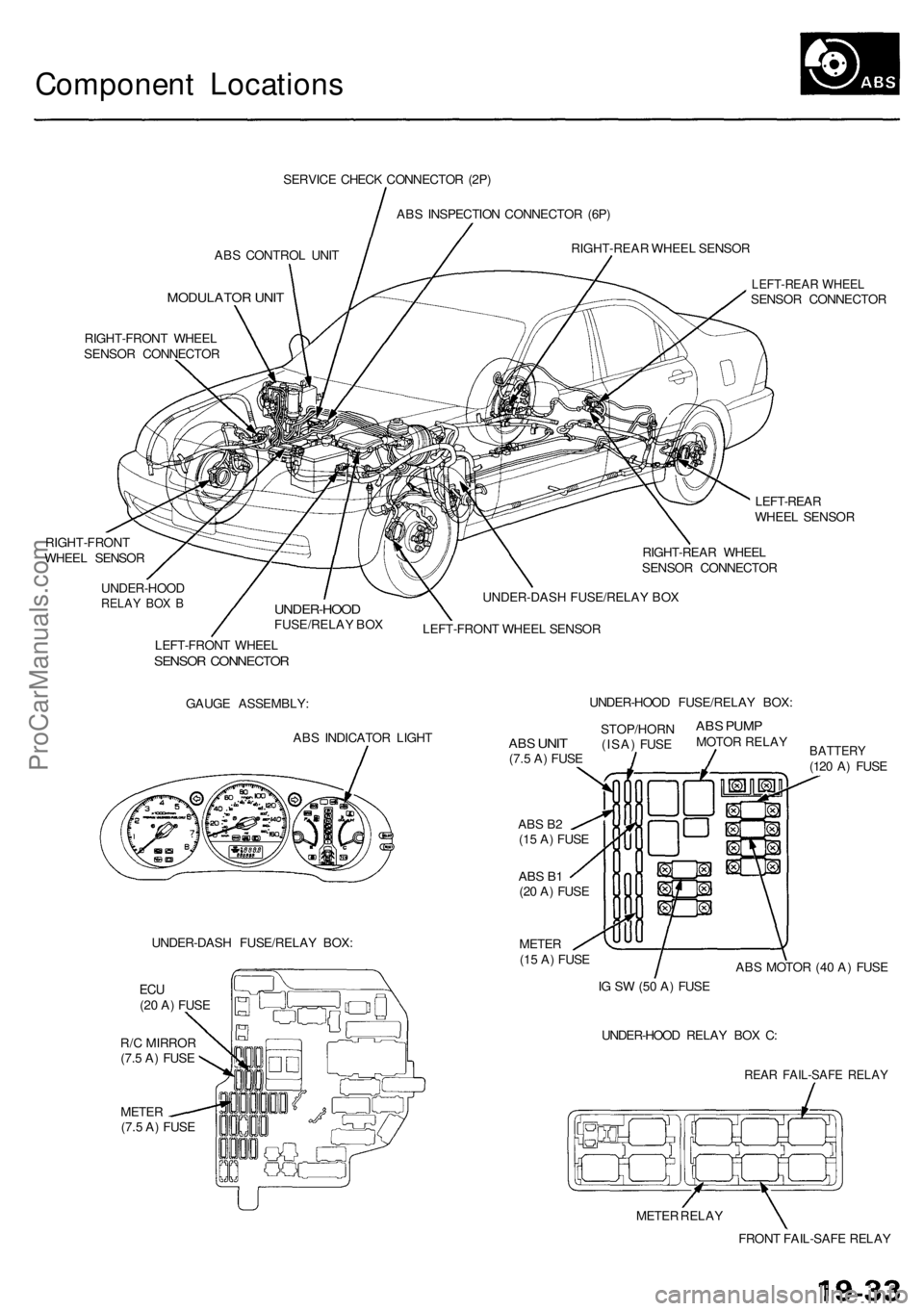
Component Locations
ABS CONTROL UNIT
MODULATOR UNIT
SERVICE CHECK CONNECTOR (2P)
ABS INSPECTION CONNECTOR (6P)
RIGHT-REAR WHEEL SENSOR
RIGHT-FRONT WHEEL
SENSOR CONNECTOR
RIGHT-FRONT
WHEEL SENSOR
LEFT-REAR WHEEL
SENSOR CONNECTOR
LEFT-REAR
WHEEL SENSOR
RIGHT-REAR WHEEL
SENSOR CONNECTOR
UNDER-HOOD
RELAY BOX B
UNDER-HOOD
FUSE/RELAY BOX
UNDER-DASH FUSE/RELAY BOX
LEFT-FRONT WHEEL SENSOR
LEFT-FRONT WHEEL
SENSOR CONNECTOR
GAUGE ASSEMBLY:
ABS INDICATOR LIGHT
UNDER-DASH FUSE/RELAY BOX:
METER
(7.5 A) FUSE
ABS B2
(15 A) FUSE
ABS B1
(20 A) FUSE
METER
(15 A) FUSE
BATTERY
(120 A) FUSE
ABS MOTOR (40 A) FUSE
IG SW (50 A) FUSE
UNDER-HOOD RELAY BOX C:
REAR FAIL-SAFE RELAY
METER RELAY
FRONT FAIL-SAFE RELAY
ABS
UNIT
(7.5 A) FUSE
STOP/HORN
(ISA) FUSE
ABS PUMP
MOTOR RELAY
UNDER-HOOD FUSE/RELAY BOX:
ECU
(20 A) FUSE
R/C MIRROR
(7.5 A) FUSEProCarManuals.com
Page 1151 of 1954
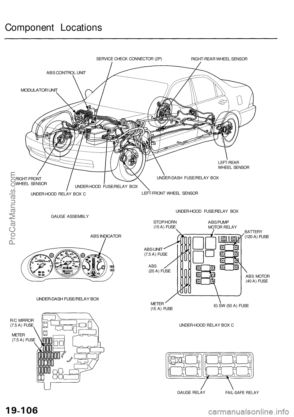
Component Locations
SERVICE CHECK CONNECTOR (2P)
RIGHT-REAR WHEEL SENSOR
ABS CONTROL UNIT
MODULATOR UNIT
LEFT-REAR
WHEEL SENSOR
RIGHT-FRONT
WHEEL SENSOR
UNDER-HOOD RELAY BOX C
UNDER-DASH FUSE/RELAY BOX
LEFT-FRONT WHEEL SENSOR
GAUGE ASSEMBLY
UNDER-HOOD FUSE/RELAY BOX
ABS INDICATOR
UNDER-DASH FUSE/RELAY BOX
R/C MIRROR
(7.5 A) FUSE
METER
(7.5 A) FUSE
STOP/HORN
(15 A) FUSE
ABS
UNIT
(7.5 A) FUSE
ABS
(20 A) FUSE
ABS PUMP
MOTOR RELAY
METER
(15 A) FUSE
BATTERY
(120 A) FUSE
ABS MOTOR
(40 A) FUSE
IG SW (50 A) FUSE
UNDER-HOOD RELAY BOX C
GAUGE RELAY
FAIL-SAFE RELAY
UNDER-HOOD FUSE/RELAY BOXProCarManuals.com
Page 1190 of 1954
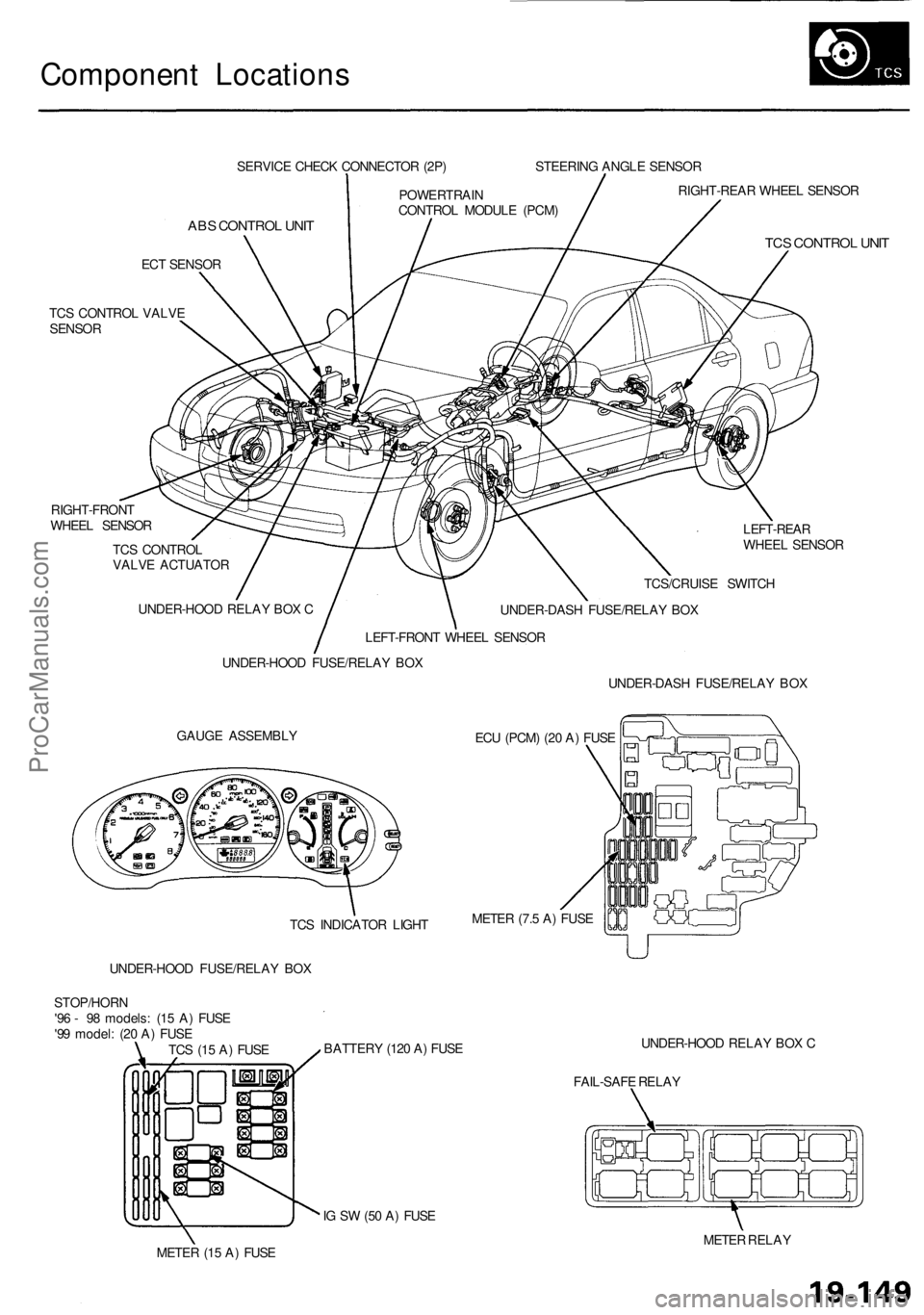
Component Locations
SERVICE CHECK CONNECTOR (2P)
ABS CONTROL UNIT
ECT SENSOR
TCS CONTROL VALVE
SENSOR
RIGHT-FRONT
WHEEL SENSOR
TCS CONTROL
VALVE ACTUATOR
LEFT-REAR
WHEEL SENSOR
GAUGE ASSEMBLY
ECU (PCM) (20 A) FUSE
UNDER-HOOD FUSE/RELAY BOX
BATTERY (120 A) FUSE
UNDER-HOOD RELAY BOX C
FAIL-SAFE RELAY
IG SW (50 A) FUSE
METER (15 A) FUSE
METER RELAY
TCS (15 A) FUSE
STOP/HORN
'96 - 98 models: (15 A) FUSE
'99 model: (20 A) FUSE
UNDER-HOOD FUSE/RELAY BOX
UNDER-HOOD RELAY BOX C
LEFT-FRONT WHEEL SENSOR
POWERTRAIN
CONTROL MODULE (PCM)
STEERING ANGLE SENSOR
RIGHT-REAR WHEEL SENSOR
TCS CONTROL UNIT
TCS/CRUISE SWITCH
UNDER-DASH FUSE/RELAY BOX
UNDER-DASH FUSE/RELAY BOX
METER (7.5 A) FUSE
TCS INDICATOR LIGHTProCarManuals.com
Page 1234 of 1954

Component Locations
SERVICE CHECK CONNECTOR (2P)
RIGHT-REAR WHEEL SENSOR
VSA CONVERTER UNIT
VSA MODULATOR
CONTROL UNIT
TCS CONTROL
VALVE SENSOR
RIGHT-FRONT
WHEEL SENSOR
PRECHARGE
PUMP MOTOR
STEERING
ANGLE SENSOR
YAW RATE/LATERAL
ACCELERATION SENSOR
TCS CONTROL VALVE
ACTUATOR
UNDER-HOOD
RELAY BOX C
UNDER-HOOD
FUSE/RELAY BOX
VSA OFF SWITCH
UNDER-DASH FUSE/RELAY BOX
LEFT-FRONT WHEEL SENSOR
LEFT-REAR
WHEEL SENSOR
GAUGE ASSEMBLY
ABS INDICATOR
VSA SYSTEM INDICATOR
UNDER-HOOD FUSE/RELAY BOX
STOP/HORN
(20 A) FUSE
BRAKE SYSTEM INDICATOR
VSA ACTIVATION INDICATOR
UNDER-DASH FUSE/RELAY BOX
TCS
(15 A) FUSE
VSA
(20 A) FUSE
METER
(15 A) FUSE
ECU
(20 A) FUSE
METER
(7.5 A) FUSE
BATTERY
(120 A) FUSE
VSA MOTOR (40 A) FUSE
IG SW (50 A) FUSE
UNDER-HOOD RELAY BOX C
FAIL-SAFE RELAY
GAUGE RELAY
PCM
R/C MIRROR
(7.5 A) FUSEProCarManuals.com
Page 1516 of 1954
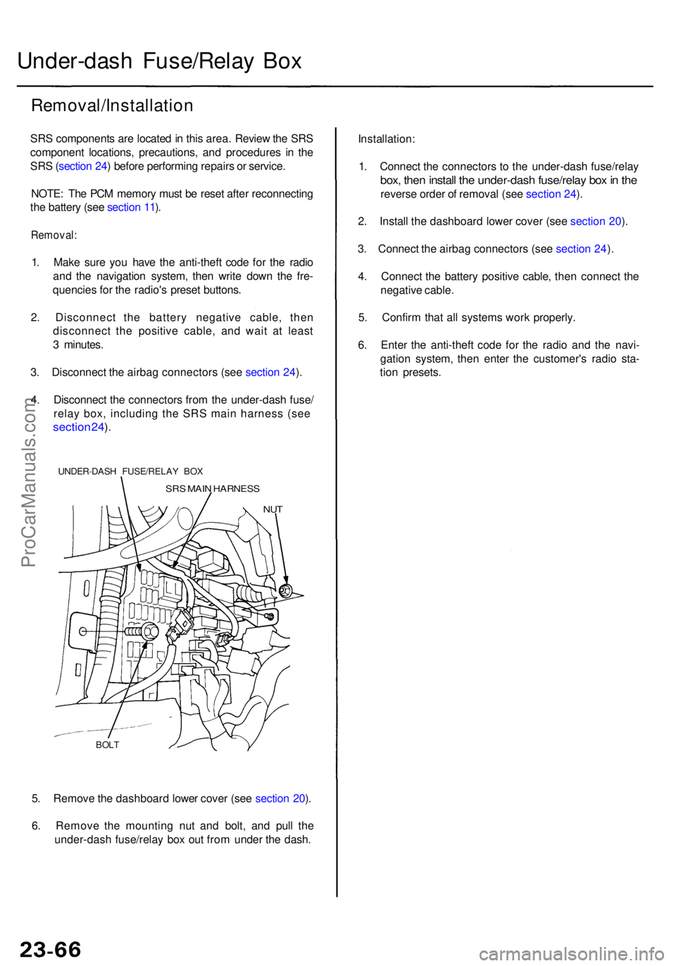
5. Remov e th e dashboar d lowe r cove r (se e sectio n 20 ).
6 . Remov e th e mountin g nu t an d bolt , an d pul l th e
under-das h fuse/rela y bo x ou t fro m unde r th e dash .
BOLT
Under-das h Fuse/Rela y Bo x
Removal/Installatio n
SRS component s ar e locate d in thi s area . Revie w th e SR S
componen t locations , precautions , an d procedure s i n th e
SR S (sectio n 24 ) befor e performin g repair s o r service .
NOTE : Th e PC M memor y mus t b e rese t afte r reconnectin g
th e batter y (se e sectio n 11 ).
Removal :
1. Mak e sur e yo u hav e th e anti-thef t cod e fo r th e radi o
an d th e navigatio n system , the n writ e dow n th e fre -
quencie s fo r th e radio' s prese t buttons .
2 . Disconnec t th e batter y negativ e cable , the n
disconnec t th e positiv e cable , an d wai t a t leas t
3 minutes .
3 . Disconnec t th e airba g connector s (se e sectio n 24 ).
4 . Disconnec t th e connector s fro m th e under-das h fuse /
relay box, including the SRS main harness (see
sectio n 24 ).
UNDER-DAS H FUSE/RELA Y BO X
SRS MAI N HARNES S
NUT
Installation :
1 . Connec t th e connector s t o th e under-das h fuse/rela y
box, the n instal l th e under-das h fuse/rela y bo x in th e
revers e orde r o f remova l (se e sectio n 24 ).
2 . Instal l th e dashboar d lowe r cove r (se e sectio n 20 ).
3 . Connec t th e airba g connector s (se e sectio n 24 ).
4 . Connec t th e batter y positiv e cable , the n connec t th e
negativ e cable .
5 . Confir m tha t al l system s wor k properly .
6 . Ente r th e anti-thef t cod e fo r th e radi o an d th e navi -
gatio n system , the n ente r th e customer' s radi o sta -
tio n presets .
ProCarManuals.com
Page 1520 of 1954
Ignition Switc h
Test
SRS component s ar e locate d i n thi s area . Revie w th e
SR S componen t locations , precautions , an d procedure s
i n th e SR S ( sectio n 24 ) befor e performin g repair s o r
service .
NOTE: Th e PC M memor y mus t b e rese t afte r reconnectin g
th e batter y (se e sectio n 11 ).
1 . Mak e sur e yo u hav e th e anti-thef t cod e fo r th e radi o
an d th e navigatio n system , the n writ e dow n th e fre -
quencie s fo r th e radio' s prese t buttons .
2 . Disconnec t th e batter y negativ e cable .
3 . Remov e th e dashboar d lowe r cove r (se e sectio n 20 ).
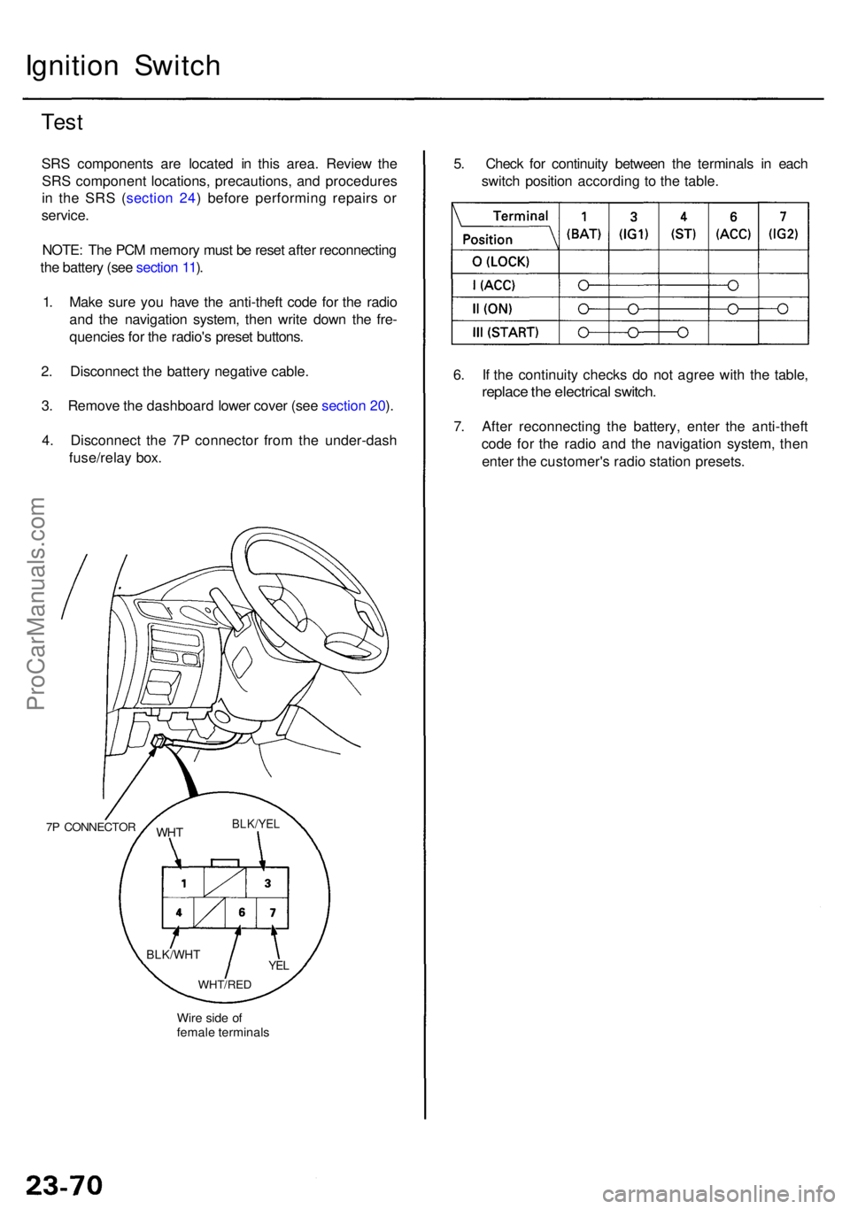
4 . Disconnec t th e 7 P connecto r fro m th e under-das h
fuse/rela y box .
7P CONNECTO R
Wire sid e o f
femal e terminal s
WHTBLK/YE L
YEL
WHT/RE D
BLK/WH T
5. Chec k fo r continuit y betwee n th e terminal s i n eac h
switc h positio n accordin g t o th e table .
6 . I f th e continuit y check s d o no t agre e wit h th e table ,
replac e th e electrica l switch .
7. Afte r reconnectin g th e battery , ente r th e anti-thef t
cod e fo r th e radi o an d th e navigatio n system , the n
ente r th e customer' s radi o statio n presets .
ProCarManuals.com
Page 1521 of 1954
8. Afte r reconnectin g th e battery , ente r th e anti-thef t
cod e fo r th e radi o an d th e navigatio n system , the n
ente r th e customer' s radi o statio n presets .
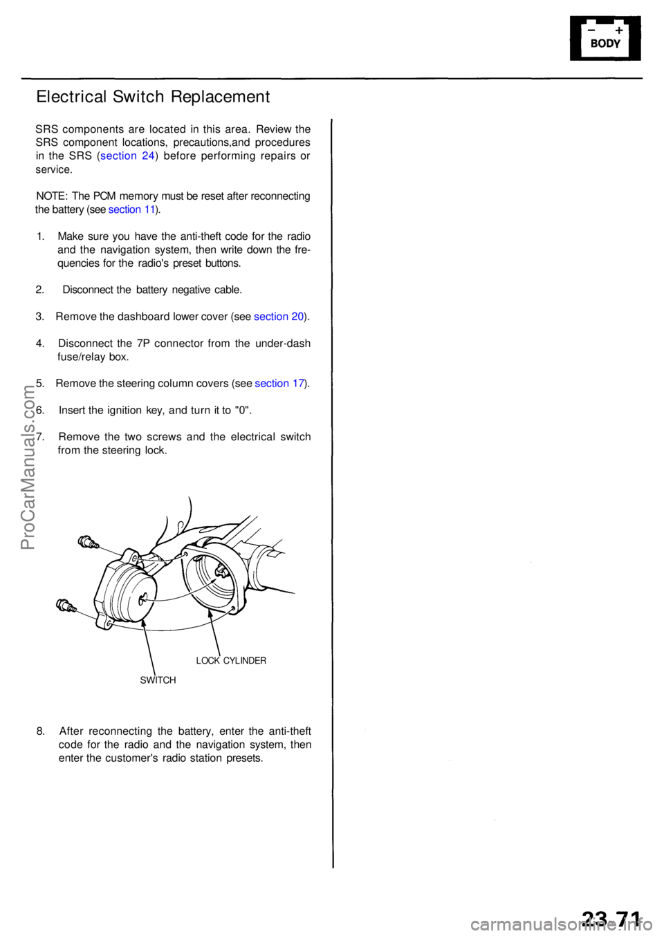
SWITCH
LOCK CYLINDE R
Electrical Switc h Replacemen t
SRS component s ar e locate d i n thi s area . Review the
SR S componen t locations , precautions,an d procedure s
i n th e SR S ( sectio n 24 ) befor e performin g repair s o r
service .
NOTE: Th e PC M memor y mus t b e rese t afte r reconnectin g
th e batter y (se e sectio n 11 ).
1 . Mak e sur e yo u hav e th e anti-thef t cod e fo r th e radi o
an d th e navigatio n system , the n writ e dow n th e fre -
quencie s fo r th e radio' s prese t buttons .
2 . Disconnec t th e batter y negativ e cable .
3 . Remov e th e dashboar d lowe r cove r (se e sectio n 20 ).
4 . Disconnec t th e 7 P connecto r fro m th e under-das h
fuse/rela y box .
5 . Remov e th e steerin g colum n cover s (se e sectio n 17 ).
6 . Inser t th e ignitio n key , an d tur n it t o "0" .
7 . Remov e th e tw o screw s an d th e electrica l switc h
fro m th e steerin g lock .
ProCarManuals.com
Page 1691 of 1954
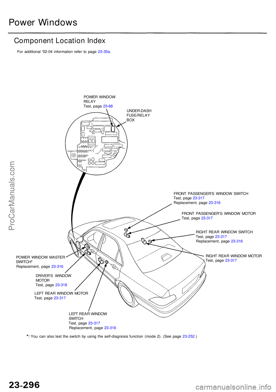
Power Window s
Component Location Index
POWER WINDO WRELAYTest, pag e 23-6 8
UNDER-DAS H
FUSE/RELAYBOX
FRON T PASSENGER' S WINDO W SWITC H
Test , pag e 23-31 7
Replacement , pag e 23-31 6
FRON T PASSENGER' S WINDO W MOTO R
Test , pag e 23-31 7
RIGH T REA R WINDO W SWITC H
Test , pag e 23-31 7
Replacement , pag e 23-31 6
RIGH T REA R WINDO W MOTO R
Test , pag e 23-31 7
POWE
R WINDO W MASTE R
SWITCH*Replacement , pag e 23-31 6
DRIVER' S WINDO W
MOTO R
Test , pag e 23-31 8
LEF T REA R WINDO W MOTO R
Test , pag e 23-31 7
LEF T REA R WINDO W
SWITC H
Test , pag e 23-31 7
Replacement , pag e 23-31 6
Yo u ca n als o tes t th e switc h b y usin g th e self-diagnosi s functio n (mod e 2) . (Se e pag e 23-252 .)For additional '02-04 information refer to page 23-35a.
ProCarManuals.com