key ACURA RL KA9 1996 Service Repair Manual
[x] Cancel search | Manufacturer: ACURA, Model Year: 1996, Model line: RL KA9, Model: ACURA RL KA9 1996Pages: 1954, PDF Size: 61.44 MB
Page 30 of 1954
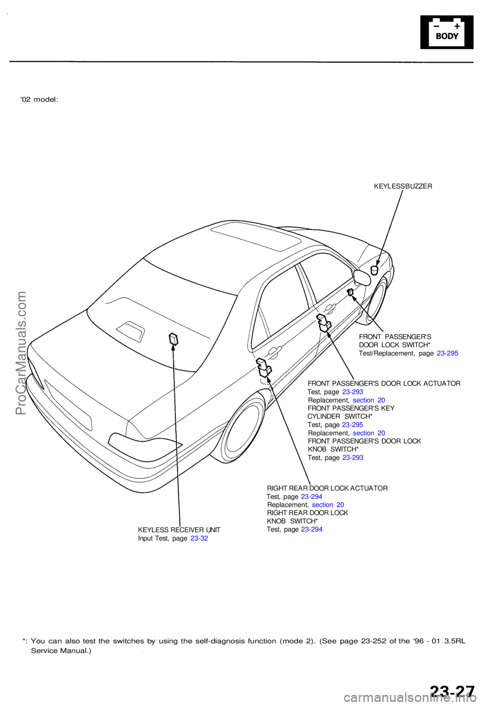
'02 model :
KEYLES S BUZZE R
FRON T PASSENGER' S
DOO R LOC K SWITCH *
Test/Replacement , pag e 23-29 5
KEYLES S RECEIVE R UNI T
Inpu t Test , pag e 23-3 2 FRON
T PASSENGER' S DOO R LOC K ACTUATO R
Test , pag e 23-29 3
Replacement , sectio n 2 0
FRON T PASSENGER' S KE Y
CYLINDE R SWITCH *
Test , pag e 23-29 5
Replacement , sectio n 2 0
FRON T PASSENGER' S DOO R LOC K
KNO B SWITCH *
Test , pag e 23-29 3
RIGH T REA R DOO R LOC K ACTUATO R
Test , pag e 23-29 4
Replacement , sectio n 2 0
RIGH T REA R DOO R LOC K
KNO B SWITCH *
Test , pag e 23-29 4
*: Yo u ca n als o tes t th e switche s b y usin g th e self-diagnosi s functio n (mod e 2) . (Se e pag e 23-25 2 o f th e '9 6 - 0 1 3.5R L
Servic e Manual. )
ProCarManuals.com
Page 31 of 1954
Power Doo r Lock s
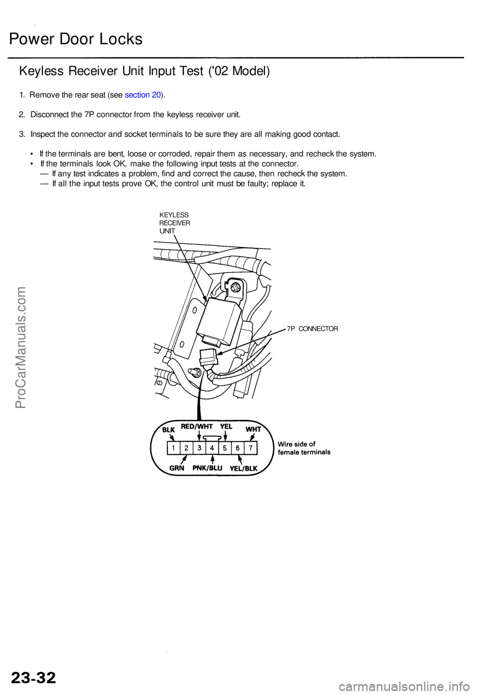
Keyles s Receive r Uni t Inpu t Tes t ('0 2 Model )
1. Remov e th e rea r sea t (se e sectio n 20 ).
2 . Disconnec t th e 7 P connecto r fro m th e keyles s receive r unit .
3 . Inspec t th e connecto r an d socke t terminal s t o b e sur e the y ar e al l makin g goo d contact .
• I f th e terminal s ar e bent , loos e o r corroded , repai r the m a s necessary , an d rechec k th e system .
• I f th e terminal s loo k OK , mak e th e followin g inpu t test s a t th e connector .
— If an y tes t indicate s a problem , fin d an d correc t th e cause , the n rechec k th e system .
— If al l th e inpu t test s prov e OK , th e contro l uni t mus t b e faulty ; replac e it .
KEYLES SRECEIVE RUNIT
7P CONNECTO R
ProCarManuals.com
Page 33 of 1954
Power Doo r Lock s
Transmitte r Tes t ('0 2-04 Models )
NOTE:
• I f th e door s unloc k o r loc k wit h th e transmitter , bu t
th e LE D o n th e transmitte r doe s no t com e on , th e
LE D is faulty ; replac e th e transmitter .
• I f an y doo r i s open , yo u canno t loc k th e doo r wit h th e
transmitter .
• I f yo u unlocke d th e door s wit h th e transmitter , bu t d o
no t ope n an y o f th e door s withi n 3 0 seconds , th e
door s reloc k automatically .
• Th e door s d o no t loc k o r unloc k wit h th e transmitte r
if th e ignitio n ke y is inserte d in th e ignitio n switch .
• Fo r PANI C butto n an d TRUN K butto n operation , hol d
th e butto n lo r mor e tha n 1 second .
1 . Pres s th e loc k o r unloc k butto n fiv e o r si x time s t o
rese t th e transmitter .
• I f th e lock s work , th e transmitte r i s OK .
• I f th e lock s don' t work , g o to ste p 2 .
2 . Ope n th e transmitte r an d chec k fo r wate r damage .
• I f yo u fin d an y wate r damage , replac e th e trans -
mitter.
• I f ther e is n o wate r damage , g o to ste p 3 .
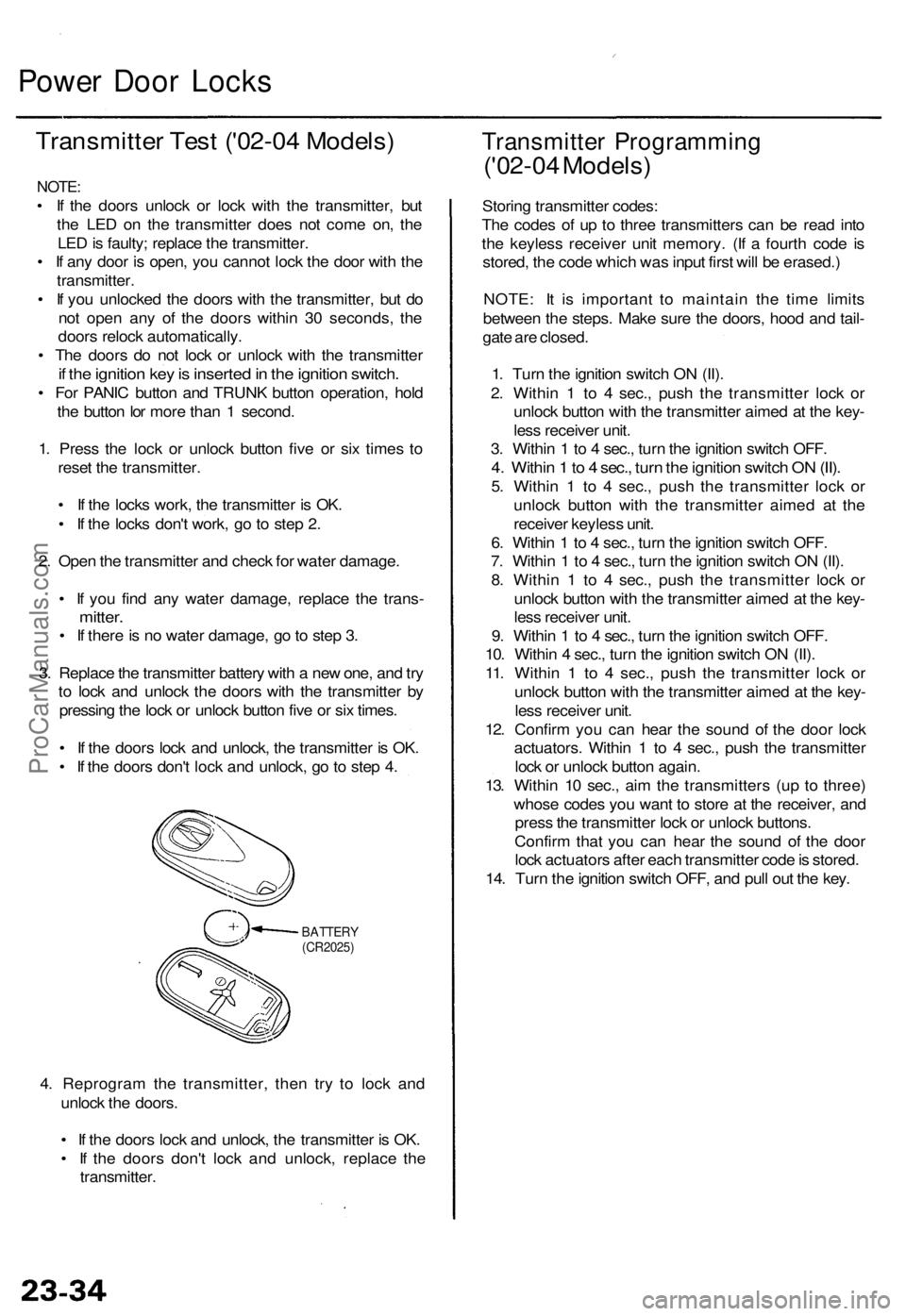
3 . Replac e th e transmitte r batter y wit h a ne w one , an d tr y
t o loc k an d unloc k th e door s wit h th e transmitte r b y
pressin g th e loc k o r unloc k butto n fiv e o r si x times .
• I f th e door s loc k an d unlock , th e transmitte r i s OK .
• I f th e door s don' t loc k an d unlock , g o to ste p 4 .
BATTER Y(CR2025)
4. Reprogra m th e transmitter , the n tr y t o loc k an d
unloc k th e doors .
• I f th e door s loc k an d unlock , th e transmitte r i s OK .
• I f th e door s don' t loc k an d unlock , replac e th e
transmitter .
Transmitte r Programmin g
('02-04 Models )
Storing transmitte r codes :
Th e code s o f u p t o thre e transmitter s ca n b e rea d int o
th e keyles s receive r uni t memory . (I f a fourt h cod e i s
stored , th e cod e whic h wa s inpu t firs t wil l b e erased. )
NOTE : I t i s importan t t o maintai n th e tim e limit s
betwee n th e steps . Mak e sur e th e doors , hoo d an d tail -
gat e ar e closed .
1 . Tur n th e ignitio n switc h O N (II) .
2 . Withi n 1 to 4 sec. , pus h th e transmitte r loc k o r
unloc k butto n wit h th e transmitte r aime d a t th e key -
les s receive r unit .
3 . Withi n 1 to 4 sec. , tur n th e ignitio n switc h OFF .
4. Withi n 1 to 4 sec. , tur n th e ignitio n switc h O N (II) .
5. Withi n 1 to 4 sec. , pus h th e transmitte r loc k o r
unloc k butto n with the transmitte r aime d a t th e
receive r keyles s unit .
6 . Withi n 1 to 4 sec. , tur n th e ignitio n switc h OFF .
7 . Withi n 1 to 4 sec. , tur n th e ignitio n switc h O N (II) .
8 . Withi n 1 to 4 sec. , pus h th e transmitte r loc k o r
unloc k butto n wit h th e transmitte r aime d a t th e key -
les s receive r unit .
9 . Withi n 1 to 4 sec. , tur n th e ignitio n switc h OFF .
10 . Withi n 4 sec. , tur n th e ignitio n switc h O N (II) .
11 . Withi n 1 to 4 sec. , pus h th e transmitte r loc k o r
unloc k butto n wit h th e transmitte r aime d a t th e key -
les s receive r unit .
12 . Confir m yo u ca n hea r th e soun d o f th e doo r loc k
actuators . Withi n 1 to 4 sec. , pus h th e transmitte r
loc k o r unloc k butto n again .
13 . Withi n 1 0 sec. , ai m th e transmitter s (u p t o three )
whos e code s yo u wan t t o stor e a t th e receiver , an d
pres s th e transmitte r loc k o r unloc k buttons .
Confir m tha t yo u can hea r th e soun d o f th e doo r
loc k actuator s afte r eac h transmitte r cod e is stored .
14 . Tur n th e ignitio n switc h OFF , an d pul l ou t th e key .
ProCarManuals.com
Page 46 of 1954
OnStar Syste m ('0 2 Mode l USA )
Descriptio n (cont'd )
Stolen vehicl e tracking :
If th e vehicl e i s stolen , th e owne r ca n repor t i t t o th e cal l center . The y wil l notif y th e authoritie s an d trac k th e vehicl e loca -
tio n t o assis t i n recovery .
Virtual advisor :
1. Virtua l adviso r setup . A subscribe r set s u p a persona l profil e o n thei r hom e compute r throug h th e interne t a t th e
OnSta r we b site .
— Stoc k portfoli o
— Traffi c
— Sport s
— New s
— Weather
— E-mai l
2 . Subscribe r call s OnSta r cal l center .
3 . OnSta r receive s an d processe s request .
4 . Profil e accesse d fo r requeste d information .
5 . OnSta r send s informatio n bac k t o subscriber . A compute r voic e relay s th e requeste d information .
Cellular phone :
The use r can mak e a hands-fre e cellula r phon e cal l wit h on e touc h (b y pressin g th e "dot " button) , an d b y usin g voic e
recognitio n commands .
Remote operation :
Vehicle door s ca n b e locke d remotel y if forgotte n o r unlocke d whe n key s ar e accidentall y lef t insid e th e vehicle . I f th e vehi -
cl e is misplace d in a parkin g lot , vehicl e aler t (honk s th e hor n an d Flashe s th e parkin g lights ) ca n b e requeste d remotely .
NOTE : Durin g norma l vehicl e operation , th e syste m is i n hig h powe r mode . Afte r th e ignitio n switc h i s turne d OF F th e sys -
te m wil l g o int o lo w powe r mod e fo r 4 8 hours , afte r tha t th e syste m wil l switc h t o slee p mod e t o conserv e batter y power .
Whe n
in lo w powe r mode , the syste m will switc h back to th e hig h powe r mod e for 1 minut e out o f ever y 10 minute s for a
perio d o f 4 8 hours . Remot e operatio n is onl y availabl e durin g th e 1 minut e perio d o f hig h powe r operation . Whe n th e sys -
te m is i n slee p mode , remot e operatio n i s no t possible .
Registerin g replacemen t components :
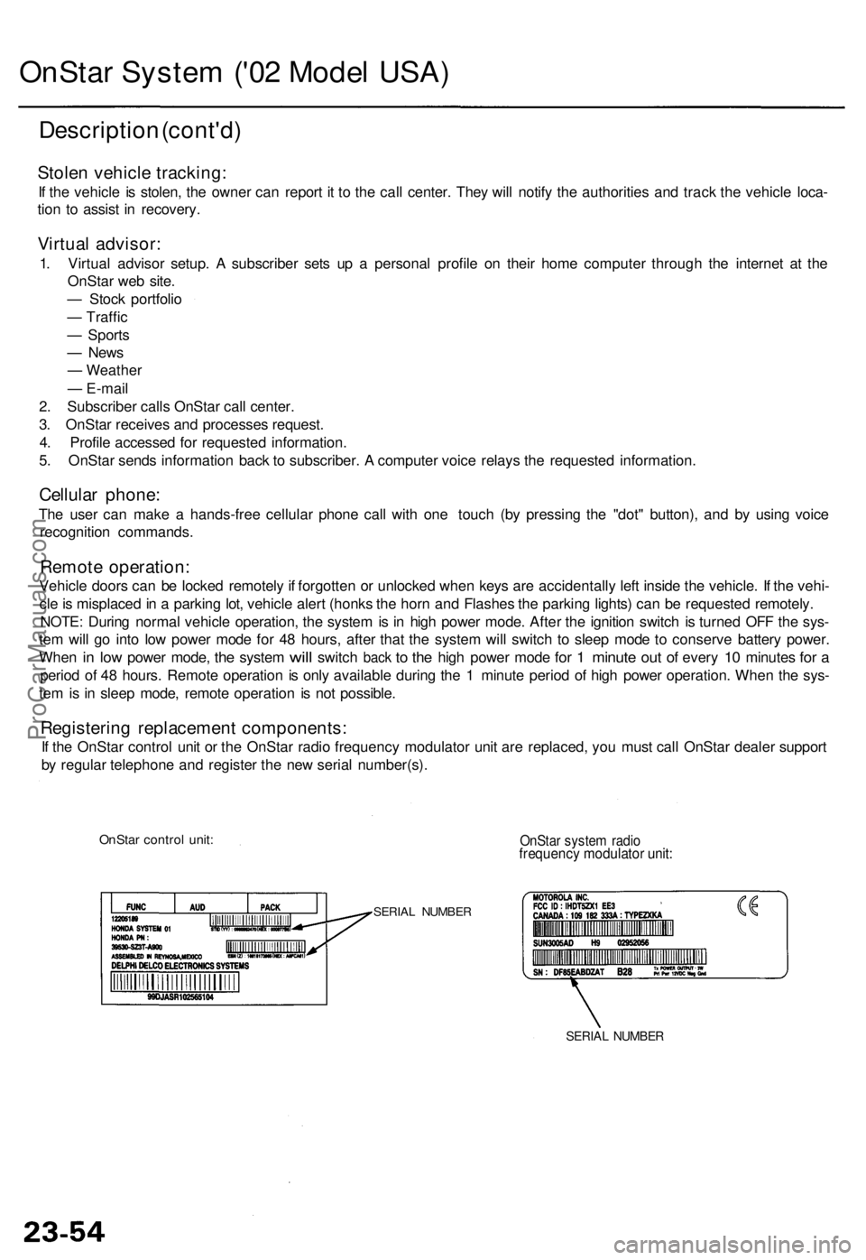
If th e OnSta r contro l uni t o r th e OnSta r radi o frequenc y modulato r uni t ar e replaced , yo u mus t cal l OnSta r deale r suppor t
b y regula r telephon e an d registe r th e ne w seria l number(s) .
OnStar contro l unit :OnSta r syste m radi ofrequenc y modulato r unit :
SERIA L NUMBE R
SERIAL NUMBE R
ProCarManuals.com
Page 50 of 1954
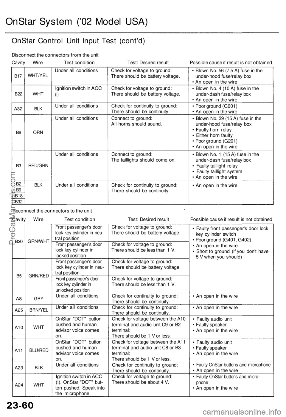
OnStar System ('02 Model USA)
OnStar Control Unit Input Test (cont'd)
Disconnect the connectors from the unit
Cavity Wire Test condition
Test: Desired result
Possible cause if result is not obtained
B17
B22
A32
B6
B3
B2
B9
B18
B32
WHT/YEL
WHT
BLK
ORN
RED/GRN
BLK
Under all conditions
Ignition switch in ACC
(I)
Under all conditions
Under all conditions
Under all conditions
Under all conditions
Check for voltage to ground:
There should be battery voltage.
Check for voltage to ground:
There should be battery voltage.
Check for continuity to ground:
There should be continuity.
Connect to ground:
All horns should sound.
Connect to ground:
The taillights should come on.
Check for continuity to ground:
There should be continuity.
• Blown No. 56 (7.5 A) fuse in the
under-hood fuse/relay box
• An open in the wire
• Blown No. 4 (10 A) fuse in the
under-dash fuse/relay box
• An open in the wire
• Poor ground (G601)
• An open in the wire
• Blown No. 39 (15 A) fuse in the
under-hood fuse/relay box
• Faulty horn relay
• Either horn faulty
• Poor ground (G201)
• An open in the wire
• Blown No. 1 (15 A) fuse in the
under-dash fuse/relay box
• Faulty taillight relay
• Faulty taillight system
• An open in the wire
• An open in the wire
Reconnect the connectors to the unit
Cavity Wire
Test condition
Test: Desired result
Possible cause if result is not obtained
B20
B5
A8
A25
A10
A11
A23
A24
GRN/WHT
GRN/RED
GRY
BRN/YEL
WHT
BLU/RED
BLK
WHT
Front passenger's door
lock key cylinder in neu-
tral position
Front passenger's door
lock key cylinder in
locked position
Front passenger's door
lock key cylinder in neu-
tral position
Front passenger's door
lock key cylinder in
unlocked position
Under all conditions
Under all conditions
OnStar "DOT" button
pushed and human
advisor voice comes
on.
OnStar "DOT" button
pushed and human
advisor voice comes
on.
Under all conditions
Ignition switch in ACC
(I). OnStar "DOT" but-
ton pushed. Speak into
the microphone.
Check for voltage to ground:
There should be battery voltage.
Check for voltage to ground:
There should be less than 1 V.
Check for voltage to ground:
There should be battery voltage.
Check for voltage to ground:
There should be less than 1 V.
Check for continuity to ground:
There should be continuity.
Check for continuity to ground:
There should be continuity.
Check for voltage between the A10
terminal and audio unit C9 or B2
terminal:
There should be 1 V or less.
Check for voltage between the A11
terminal and audio unit C8 or B3
terminal:
There should be 1 V or less.
Check for continuity to ground:
There should be continuity.
Check for voltage to ground:
There should be about 4 V.
• Faulty front passenger's door lock
key cylinder switch
• Poor ground (G401, G402)
• An open in the wire
• Short to ground (if you don't have
5 V when you should)
• An open in the wire
• An open in the wire
• Faulty audio unit
• Faulty speaker
• An open in the wire
• Faulty audio unit
• Faulty speaker
• An open in the wire
• Faulty OnStar buttons and microphone
• An open in the wire
• Faulty OnStar buttons and micro-
phone
• An open in the wireProCarManuals.com
Page 245 of 1954
Navigation System
System Description (cont'd)
Audio Unit
The audio unit receives the audio driving instructions from the navigation unit and transmits the instructions through the
front speakers even when the audio system is in use.
Display Unit
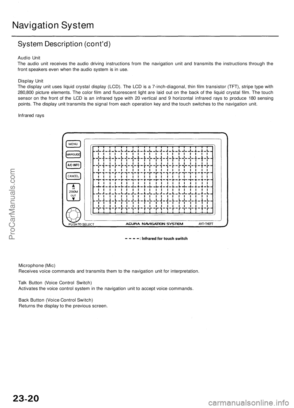
The display unit uses liquid crystal display (LCD). The LCD is a 7-inch-diagonal, thin film transistor (TFT), stripe type with
280,800 picture elements. The color film and fluorescent light are laid out on the back of the liquid crystal film. The touch
sensor on the front of the LCD is an infrared type with 20 vertical and 9 horizontal infrared rays to produce 180 sensing
points. The display unit transmits the signal from each operation key and the touch switches to the navigation unit.
Infrared rays
Microphone (Mic)
Receives voice commands and transmits them to the navigation unit for interpretation.
Talk Button (Voice Control Switch)
Activates the voice control system in the navigation unit to accept voice commands.
Back Button (Voice Control Switch)
Returns the display to the previous screen.ProCarManuals.com
Page 247 of 1954
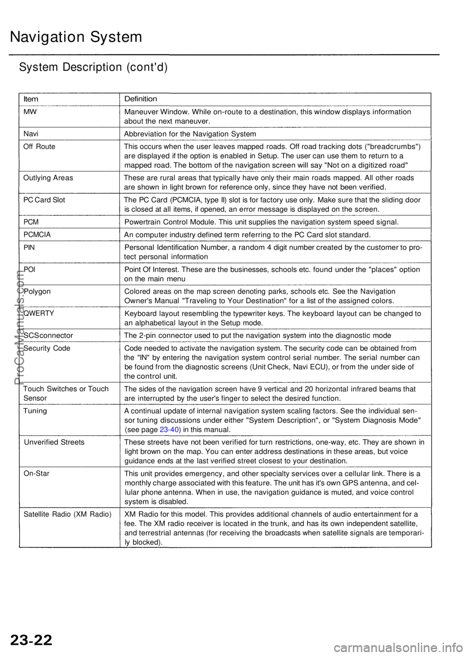
Navigation Syste m
System Descriptio n (cont'd )
Item
MW
Nav i
Off Rout e
Outlyin g Area s
PC Car d Slo t
PCM
PCMCI A
PIN
PO I
Polygo n
QWERT Y
SCS connecto r
Security Cod e
Touc h Switche s o r Touc h
Senso r
Tuning
Unverifie d Street s
On-Sta r
Satellite Radi o (X M Radio )
Definitio n
Maneuve r Window . Whil e on-rout e to a destination , thi s windo w display s informatio n
about th e nex t maneuver .
Abbreviatio n fo r th e Navigatio n Syste m
This occur s whe n th e use r leave s mappe d roads . Of f roa d trackin g dot s ("breadcrumbs" )
are displaye d if th e optio n is enable d in Setup . Th e use r ca n us e the m to retur n t o a
mappe d road . Th e botto m o f th e navigatio n scree n wil l sa y "No t o n a digitize d road "
These ar e rura l area s tha t typicall y hav e onl y their main road s mapped . Al l othe r road s
are show n in ligh t brow n fo r referenc e only , sinc e the y hav e no t bee n verified .
The P C Car d (PCMCIA , typ e II ) slo t i s fo r factor y us e only . Mak e sur e tha t th e slidin g doo r
is close d a t al l items , i f opened , a n erro r messag e is displaye d o n th e screen .
Powertrai n Contro l Module . Thi s uni t supplie s th e navigatio n syste m spee d signal .
An compute r industr y define d ter m referrin g t o th e P C Car d slo t standard .
Personal Identificatio n Number , a rando m 4 digi t numbe r create d b y th e custome r t o pro -
tect persona l informatio n
Point O f Interest . Thes e ar e th e businesses , school s etc . foun d unde r th e "places " optio n
on th e mai n men u
Colore d area s o n th e ma p scree n denotin g parks , school s etc . Se e th e Navigatio n
Owner's Manua l "Travelin g t o You r Destination " fo r a lis t o f th e assigne d colors .
Keyboar d layou t resemblin g th e typewrite r keys . Th e keyboar d layou t ca n b e change d t o
a n alphabetica l layou t i n th e Setu p mode .
The 2-pi n connecto r use d t o pu t th e navigatio n syste m int o th e diagnosti c mod e
Code neede d to activat e th e navigatio n system . Th e securit y cod e ca n b e obtaine d fro m
the "IN " b y enterin g th e navigatio n syste m contro l seria l number . Th e seria l numbe r ca n
be foun d fro m th e diagnosti c screen s (Uni t Check , Nav i ECU) , o r fro m th e unde r sid e o f
the contro l unit .
The side s o f th e navigatio n scree n hav e 9 vertica l an d 2 0 horizonta l infrare d beam s tha t
are interrupte d b y th e user' s finge r t o selec t th e desire d function .
A continua l updat e o f interna l navigatio n syste m scalin g factors . Se e th e individua l sen -
sor tunin g discussion s unde r eithe r "Syste m Description" , o r "Syste m Diagnosi s Mode "
(see pag e 23-40 ) i n thi s manual .
These street s hav e no t bee n verifie d fo r tur n restrictions , one-way , etc . The y ar e show n i n
ligh t brow n o n th e map . Yo u ca n ente r addres s destination s i n thes e areas , bu t voic e
guidanc e end s a t th e las t verifie d stree t closes t t o you r destination .
This uni t provide s emergency , an d othe r specialt y service s ove r a cellula r link . Ther e is a
monthl y charg e associate d wit h thi s feature . Th e uni t ha s it' s ow n GP S antenna , an d cel -
lula r phon e antenna . Whe n in use , th e navigatio n guidanc e is muted , an d voic e contro l
system is disabled .
XM Radi o fo r thi s model . Thi s provide s additiona l channel s o f audi o entertainmen t fo r a
fee . Th e X M radi o receive r i s locate d in th e trunk , an d ha s it s ow n independen t satellite ,
and terrestria l antenna s (fo r receivin g th e broadcast s whe n satellit e signal s ar e temporari -
ly blocked) .
ProCarManuals.com
Page 264 of 1954
+
BODY
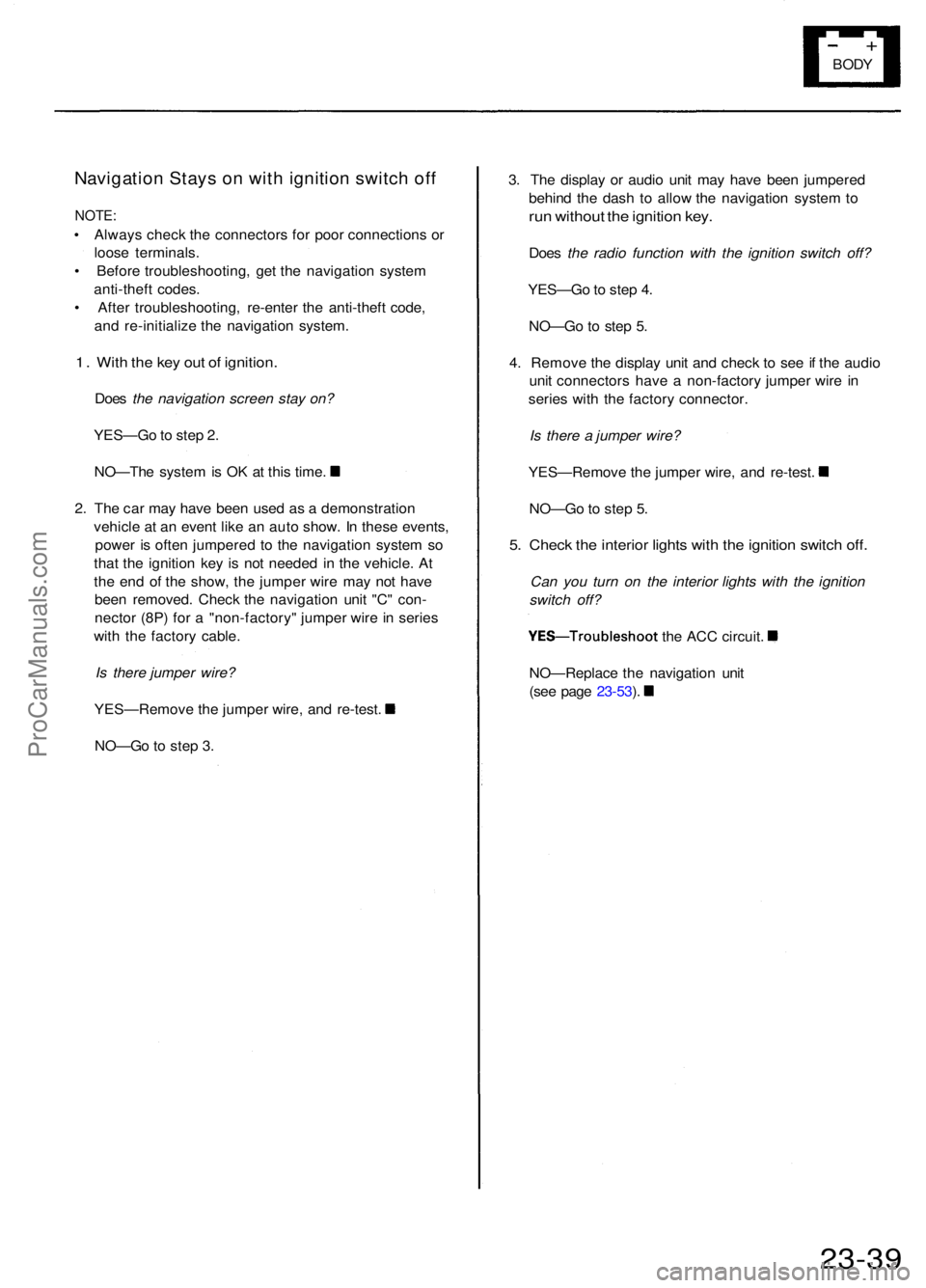
Navigatio n Stay s o n wit h ignitio n switc h of f
NOTE :
• Alway s chec k th e connector s fo r poo r connection s o r
loos e terminals .
• Befor e troubleshooting , ge t th e navigatio n syste m
anti-thef t codes .
• Afte r troubleshooting , re-ente r th e anti-thef t code ,
an d re-initializ e th e navigatio n system .
1. Wit h th e ke y ou t o f ignition .
Does the navigation screen stay on?
YES—G o to ste p 2 .
NO—Th e syste m is O K a t thi s time .
2 . Th e ca r ma y hav e bee n use d a s a demonstratio n
vehicl e a t a n even t lik e a n aut o show . I n thes e events ,
powe r i s ofte n jumpere d t o th e navigatio n syste m s o
tha t th e ignitio n ke y i s no t neede d i n th e vehicle . A t
th e en d o f th e show , th e jumpe r wir e ma y no t hav e
bee n removed . Chec k th e navigatio n uni t "C " con -
necto r (8P ) fo r a "non-factory " jumpe r wir e in serie s
wit h th e factor y cable .
Is there jumper wire?
YES—Remov e th e jumpe r wire , an d re-test .
NO—G o t o ste p 3 . 3
. Th e displa y o r audi o uni t ma y hav e bee n jumpere d
behin d th e das h t o allo w th e navigatio n syste m to
ru n withou t th e ignitio n key .
Doe s the radio function with the ignition switch off?
YES—G o to ste p 4 .
NO—G o t o ste p 5 .
4 . Remov e th e displa y uni t an d chec k t o se e if th e audi o
uni t connector s hav e a non-factor y jumpe r wir e i n
serie s wit h th e factor y connector .
Is there a jumper wire?
YES—Remov e th e jumpe r wire , an d re-test .
NO—G o to ste p 5 .
5. Chec k th e interio r light s wit h th e ignitio n switc h off .
Can you turn on the interior lights with the ignition
switch off?
YES—Troubleshoo t the AC C circuit .
NO—Replac e th e navigatio n uni t
(se e pag e 23-53 ).
23-3 9
ProCarManuals.com
Page 326 of 1954
Starting Syste m
Starte r Tes t (cont'd )
Check fo r Wea r an d Damag e
Th e starte r shoul d cran k th e engin e smoothl y an d steadily .
I f th e starte r engages , bu t crank s th e engin e erratically ,
remov e it , an d inspec t th e starte r driv e gea r an d driv e
plat e rin g gea r fo r damage .
Chec k th e driv e gea r overrunning clutch fo r bindin g o r
slippin g whe n th e armatur e is rotate d wit h th e driv e gea r
held . I f th e clutc h i s damaged , replac e th e clutc h assem -
bly.
Chec k Crankin g Voltag e an d Curren t Dra w
Crankin g voltag e shoul d b e n o les s tha n 8. 0 volts .
Curren t draw shoul d b e n o mor e tha n 40 0 amperes .
I f crankin g voltag e i s to o low , o r curren t draw too high ,
chec k for :
Dea d o r lo w batter y
Ope n circui t i n starte r armatur e commutato r segment s
Starte r armatur e draggin g
Shorte d armatur e windin g
Excessiv e dra g in engin e
Chec k Crankin g rp m
Engin e spee d durin g crankin g shoul d b e abov e 10 0 rpm .
I f spee d is to o low , chec k for :
Loos e batter y o r starte r terminal s
Excessivel y wor n starte r brushe s
Ope n circui t i n commutato r segment s
Dirt y o r damage d helica l splin e o r driv e gea r
Defectiv e driv e gea r overrunnin g clutc h
Chec k Starte r Disengagemen t
With th e shif t leve r i n tur n th e ignitio n switc h t o
"STAR T (III)" , an d releas e t o "O N (II)" . Th e starte r driv e
gea r shoul d disengag e fro m th e driv e plat e rin g gea r
whe n yo u releas e th e key .
I f th e driv e gea r hang s u p o n th e driv e plat e rin g gear ,
check for :
• Solenoi d plunge r an d switc h malfunctio n
• Dirt y driv e gea r assembl y o r damage d overrunnin g
clutc h
ProCarManuals.com
Page 386 of 1954
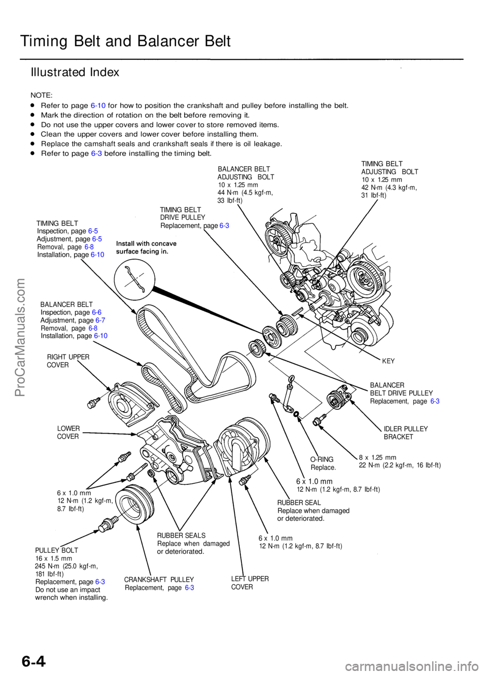
Timing Bel t an d Balance r Bel t
Illustrate d Inde x
NOTE :
Refer t o pag e 6-1 0 fo r ho w to positio n th e crankshaf t an d pulle y befor e installin g th e belt .
Mark th e directio n o f rotatio n o n th e bel t befor e removin g it .
Do no t us e th e uppe r cover s an d lowe r cove r t o stor e remove d items .
Clean th e uppe r cover s an d lowe r cove r befor e installin g them .
Replac e th e camshaf t seal s an d crankshaf t seal s i f ther e i s oi l leakage .
Refer t o pag e 6- 3 befor e installin g th e timin g belt .
TIMIN G BEL TADJUSTIN G BOL T10 x 1.2 5 mm42 N- m (4. 3 kgf-m ,
3 1 Ibf-ft )
TIMIN G BEL TInspection , pag e 6- 5Adjustment , pag e 6- 5Removal , pag e 6- 8Installation , pag e 6-1 0
BALANCE R BEL TInspection , pag e 6- 6Adjustment , pag e 6- 7Removal , pag e 6- 8Installation , pag e 6-1 0
RIGH T UPPE R
COVE R
TIMING BEL TDRIV E PULLE YReplacement , pag e 6- 3
LOWE R
COVE R BALANCE
R
BEL T DRIV E PULLE Y
Replacement , pag e 6- 3
IDLE R PULLE YBRACKE T
8 x 1.2 5 mm22 N- m (2. 2 kgf-m , 1 6 Ibf-ft )
PULLE Y BOL T
16 x 1. 5 m m245 N- m (25. 0 kgf-m ,
18 1 Ibf-ft )
Replacement , pag e 6- 3Do no t us e a n impac twrench whe n installing .
6 x 1. 0 m m12 N- m (1. 2 kgf-m , 8. 7 Ibf-ft )
RUBBE R SEA L
Replac e whe n damage dor deteriorated .
6 x 1. 0 m m12 N- m (1. 2 kgf-m , 8. 7 Ibf-ft )
CRANKSHAF T PULLE Y
Replacement , pag e 6- 3 LEF
T UPPE R
COVE R
O-RINGReplace .
RUBBE R SEAL S
Replac e whe n damage d
or deteriorated .
6 x 1. 0 m m12 N- m (1. 2 kgf-m ,
8. 7 Ibf-ft ) BALANCE
R BEL T
ADJUSTIN G BOL T
10 x 1.2 5 mm44 N- m (4. 5 kgf-m ,
3 3 Ibf-ft )
KEY
ProCarManuals.com