manual radio set ACURA RL KA9 1996 Service Repair Manual
[x] Cancel search | Manufacturer: ACURA, Model Year: 1996, Model line: RL KA9, Model: ACURA RL KA9 1996Pages: 1954, PDF Size: 61.44 MB
Page 230 of 1954
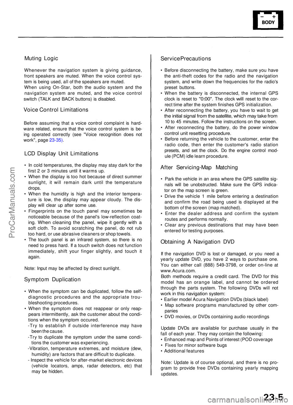
Muting Logi c
Wheneve r th e navigatio n syste m is givin g guidance ,
fron t speaker s ar e muted . Whe n th e voic e contro l sys -
te m is bein g used , al l o f th e speaker s ar e muted .
Whe n usin g On-Star , bot h th e audi o syste m an d th e
navigatio n syste m ar e muted , an d th e voic e contro l
switc h (TAL K an d BAC K buttons ) i s disabled .
Voice Contro l Limitation s
Before assumin g tha t a voic e contro l complain t i s hard -
war e related , ensur e tha t th e voic e contro l syste m is be -
in g operate d correctl y (se e "Voic e recognitio n doe s no t
work" , pag e 23-35) .
LCD Displa y Uni t Limitation s
• I n col d temperatures , th e displa y ma y sta y dar k fo r th e
firs t 2 o r 3 minute s unti l i t warm s up .
• Whe n th e displa y i s to o ho t becaus e o f direc t summe r
sunlight , i t wil l remai n dar k unti l th e temperatur e
drops .
• Whe n th e humidit y i s hig h an d th e interio r tempera -
tur e i s low , th e displa y ma y appea r cloudy . Th e dis -
pla y wil l clea r u p afte r som e use .
• Fingerprint s o n th e touc h pane l ma y sometime s b e
noticeabl e becaus e o f th e panel' s low-reflectio n coat -
ing. Whe n cleanin g th e panel , wip e i t gentl y wit h a
sof t cloth . T o avoi d scratchin g th e panel , d o no t ru b
to o hard , o r us e abrasiv e cleaner s o r sho p towels .
• Th e touc h pane l i s a n infrare d system , s o ther e i s n o
nee d t o pres s hard . I f a touc h switc h doe s no t functio n
immediately , shif t you r finge r slightly , an d touc h i t
again .
Note : Inpu t ma y b e affecte d b y direc t sunlight .
Symptom Duplicatio n
• Whe n th e sympto m ca n b e duplicated , follo w th e self -
diagnosti c procedure s an d th e appropriat e trou -
bleshootin g procedures .
• Whe n th e sympto m doe s no t reappea r o r onl y reap -
pear s intermittently , as k th e custome r abou t th e condi -
tion s whe n th e sympto m occured .
-Tr y t o establis h i f outsid e interferenc e ma y hav e
bee n th e cause .
-Tr y t o duplicat e th e sympto m unde r th e sam e condi -
tion s th e custome r wa s experiencing .
-Vibration , temperatur e extremes , an d moistur e (dew ,
humidity ) ar e factor s tha t ar e difficul t t o duplicate .
- Inspec t th e vehicl e fo r after-marke t electroni c device s
(vehicl e locators , amps , rada r detectors , etc) that
ma y b e hidden .
Service Precaution s
• Befor e disconnectin g th e battery , mak e sur e yo u hav e
th e anti-thef t code s fo r th e radi o an d th e navigatio n
system , an d writ e dow n th e frequencie s fo r th e radio' s
prese t buttons .
• Whe n th e batter y i s disconnected , th e interna l GP S
cloc k
is rese t to "0:00" . The cloc k will rese t to th e cor -
rec t tim e afte r th e syste m finishe s GP S initialization .
• Afte r reconnectin g th e battery , yo u hav e t o wai t t o ge t
the initia l signa l fro m th e satellite , whic h ma y tak e fro m
10 to 4 5 minutes . Follo w th e instruction s o n th e screen .
• Afte r reconnectin g th e battery , d o th e powe r windo w
control uni t resettin g procedure .
• Befor e returnin g th e vehicl e t o th e customer , ente r th e
radi o code , the n ente r th e customer' s radi o statio n
presets , an d se t th e clock . D o th e engin e contro l mod -
ul e (PCM ) idl e lear n procedure .
After Servicing-Ma p Matchin g
• Par k th e vehicl e in a n are a wher e th e GP S satellit e sig -
nal s wil l b e unobstructed . Mak e sur e th e GP S indica -
to r o n th e ma p scree n i s green .
• Driv e th e vehicl e 1 mil e befor e enterin g a destinatio n
an d confir m th e roa d bein g use d i s displaye d a t th e
botto m o f th e scree n (ma p matched) .
• Ente r th e deale r addres s an d confir m th e syste m
route s an d perform s normally .
• Clea r an y previou s destination s tha t ma y hav e bee n
entere d fo r testin g purposes .
Obtaining A Navigatio n DV D
If th e navigatio n DV D is los t o r damaged , o r yo u nee d a
yearl y updat e DVD , yo u hav e 2 way s t o purchas e one .
Yo u ca n eithe r cal l (888 ) 549-3798 , o r orde r on-lin e a t
www.Acura.com .
Both method s requir e a credi t card . Th e DV D fo r thi s
mode l ha s a n orang e label , an d canno t b e ordere d
throug h th e part s system . Th e followin g DVD s wil l no t
wor k in thi s navigatio n system :
• Earlie r mode l Acur a Navigatio n DVD s (blac k label )
• Ma p softwar e program s manufacture d b y othe r com -
panie s
• DV D movies , o r DVD s containin g audi o recording s
Updat e DVD s ar e availabl e fo r purchas e usuall y i n th e
fal l o f eac h year . The y ma y contai n th e following :
• Enhance d ma p an d Point s o f interes t (PO D coverag e
• Fixe s fo r mino r softwar e bug s
• Additiona l feature s
Note : Updat e i s o f cours e optional , an d ther e i s n o pro -
gra m to provid e fre e DVD s containin g yearl y mappin g
updates.
ProCarManuals.com
Page 239 of 1954
Navigation System
System Description (cont'd)
Overview
The Acura Navigation System is a highly-sophisticated, hybrid locating system that uses satellites and a map database to
show you where you are and to help guide you to a desired destination.
The navigation system receives signals from the Global Positioning System (GPS), a network of 24 satellites in orbit
around the earth. By receiving signals from serveral of these satellites, the navigation system can determine the latitude,
longitude, and elevation of the vehicle. In addition, signals from the system's yaw rate sensor and the PCM (vehicle
speed pulse) enable the system to keep track of the vehicle's direction and speed of travel.
This hybrid system has advantages over a system that is either entirely self-contained or one that relies totally on the
GPS. For example, the self-contained portion of the system can keep track of vehicle position even when satellite signals
cannot be received. When the navigation system is on, the GPS can keep track of the vehicle position even when the vehi-
cle is transported by ferry.
The navigation system applies all this location, direction, and speed information to the maps and calculates a route to the
destination entered. As you drive to that destination, the system provides both visual and audio guidance.
This navigation system also has voice recognition that allows voice control of most of the navigation functions. The TALK
and BACK buttons on the steering wheel activate the voice control.
The illumination signal is used for two purposes. The display unit uses the signal to light up the hard buttons surrounding
the display. In addition the signal is used by the navigation unit to automatically switch from the "Day" to "Night" display
mode when the headlights are on. This automatic switching occurs only if the "Display" setting in setup screen 1 is set to
"AUTO". If the headlights are on and the customer has the dash light brightness control to "full bright," then this overrides
the "Night" mode.
The use of the audio speakers follows a hierarchy. The highest priority is the OnStar voice, followed by the navigation voice,
and finally the radio/CD. The audio unit enforces this hierarchy. The GA-Net bus is used to pass commands to mute the speak-
ers, and to disable the voice control system. Prior systems used dedicated wires to accomplish this function.
• If On-Star is in use, the audio unit passes a command on the GA-Net bus to the navigation unit to disable the voice control
system. The navigation unit then ignores the voice control switch, and temporarily ceases voice route guidance prompts.
• When the navigation system issues route guidance, the navigation unit uses the GA-Net bus to tell the audio unit to mute just
the front speakers. When the voice control system is being used (the TALK/BACK buttons), the navigation unit uses the GA-
Net bus to tell the audio unit to mute all speakers.ProCarManuals.com
Page 247 of 1954
Navigation Syste m
System Descriptio n (cont'd )
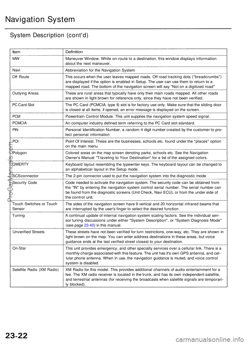
Item
MW
Nav i
Off Rout e
Outlyin g Area s
PC Car d Slo t
PCM
PCMCI A
PIN
PO I
Polygo n
QWERT Y
SCS connecto r
Security Cod e
Touc h Switche s o r Touc h
Senso r
Tuning
Unverifie d Street s
On-Sta r
Satellite Radi o (X M Radio )
Definitio n
Maneuve r Window . Whil e on-rout e to a destination , thi s windo w display s informatio n
about th e nex t maneuver .
Abbreviatio n fo r th e Navigatio n Syste m
This occur s whe n th e use r leave s mappe d roads . Of f roa d trackin g dot s ("breadcrumbs" )
are displaye d if th e optio n is enable d in Setup . Th e use r ca n us e the m to retur n t o a
mappe d road . Th e botto m o f th e navigatio n scree n wil l sa y "No t o n a digitize d road "
These ar e rura l area s tha t typicall y hav e onl y their main road s mapped . Al l othe r road s
are show n in ligh t brow n fo r referenc e only , sinc e the y hav e no t bee n verified .
The P C Car d (PCMCIA , typ e II ) slo t i s fo r factor y us e only . Mak e sur e tha t th e slidin g doo r
is close d a t al l items , i f opened , a n erro r messag e is displaye d o n th e screen .
Powertrai n Contro l Module . Thi s uni t supplie s th e navigatio n syste m spee d signal .
An compute r industr y define d ter m referrin g t o th e P C Car d slo t standard .
Personal Identificatio n Number , a rando m 4 digi t numbe r create d b y th e custome r t o pro -
tect persona l informatio n
Point O f Interest . Thes e ar e th e businesses , school s etc . foun d unde r th e "places " optio n
on th e mai n men u
Colore d area s o n th e ma p scree n denotin g parks , school s etc . Se e th e Navigatio n
Owner's Manua l "Travelin g t o You r Destination " fo r a lis t o f th e assigne d colors .
Keyboar d layou t resemblin g th e typewrite r keys . Th e keyboar d layou t ca n b e change d t o
a n alphabetica l layou t i n th e Setu p mode .
The 2-pi n connecto r use d t o pu t th e navigatio n syste m int o th e diagnosti c mod e
Code neede d to activat e th e navigatio n system . Th e securit y cod e ca n b e obtaine d fro m
the "IN " b y enterin g th e navigatio n syste m contro l seria l number . Th e seria l numbe r ca n
be foun d fro m th e diagnosti c screen s (Uni t Check , Nav i ECU) , o r fro m th e unde r sid e o f
the contro l unit .
The side s o f th e navigatio n scree n hav e 9 vertica l an d 2 0 horizonta l infrare d beam s tha t
are interrupte d b y th e user' s finge r t o selec t th e desire d function .
A continua l updat e o f interna l navigatio n syste m scalin g factors . Se e th e individua l sen -
sor tunin g discussion s unde r eithe r "Syste m Description" , o r "Syste m Diagnosi s Mode "
(see pag e 23-40 ) i n thi s manual .
These street s hav e no t bee n verifie d fo r tur n restrictions , one-way , etc . The y ar e show n i n
ligh t brow n o n th e map . Yo u ca n ente r addres s destination s i n thes e areas , bu t voic e
guidanc e end s a t th e las t verifie d stree t closes t t o you r destination .
This uni t provide s emergency , an d othe r specialt y service s ove r a cellula r link . Ther e is a
monthl y charg e associate d wit h thi s feature . Th e uni t ha s it' s ow n GP S antenna , an d cel -
lula r phon e antenna . Whe n in use , th e navigatio n guidanc e is muted , an d voic e contro l
system is disabled .
XM Radi o fo r thi s model . Thi s provide s additiona l channel s o f audi o entertainmen t fo r a
fee . Th e X M radi o receive r i s locate d in th e trunk , an d ha s it s ow n independen t satellite ,
and terrestria l antenna s (fo r receivin g th e broadcast s whe n satellit e signal s ar e temporari -
ly blocked) .
ProCarManuals.com
Page 258 of 1954
Voice guidanc e canno t b e hear d
Diagnosti c Test : Navigatio n Syste m Lin k
NOTE :
• Alway s chec k th e connector s fo r poo r connection s o r
loos e terminals .
• Befor e troubleshooting , writ e dow n th e customer' s
radi o statio n presets , an d ge t th e radi o an d naviga -
tio n syste m anti-thef t codes .
• Afte r troubleshooting , ente r th e radi o an d navigatio n
syste m anti-thef t codes , an d th e radi o statio n presets .
1 . Pres s th e displa y uni t A/ C INF O button , an d selec t
"set-up" .
2 . Chec k th e volum e settin g fo r th e navigatio n system .
Is it set OFF?
YES—Se t th e volum e to a n audibl e level .
NO—G o t o ste p 3 .
3 . Chec k th e radi o operation .
Can you hear the radio?
YES—G o to ste p 4 .
NO—Troubleshoo t the audi o system .
4 . G o int o th e Diagnosti c mod e an d us e th e "Nav i
Syste m Link " diagnosti c (se e pag e 23-40 ) t o chec k
th e radio .
Is "Radio" icon red?
YES—Troubleshoo t the audi o system .
NO—G o t o ste p 5 . Is
there continuity?
YES—Replac e th e affecte d shielde d harness .
NO—G o t o ste p 8 .
(cont'd)
5
. Tur n th e ignitio n switc h OFF .
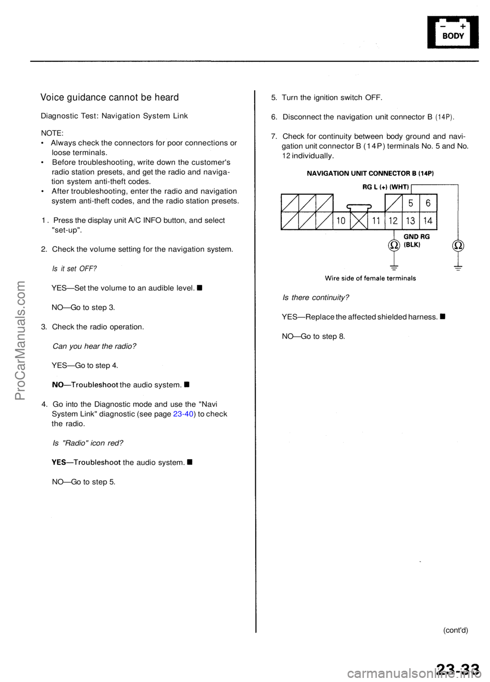
6. Disconnec t the navigatio n unit connecto r B (14P).
7. Chec k fo r continuit y betwee n bod y groun d an d navi -
gatio n uni t connecto r B (14P ) terminal s No . 5 an d No .
12 individually .
ProCarManuals.com
Page 327 of 1954
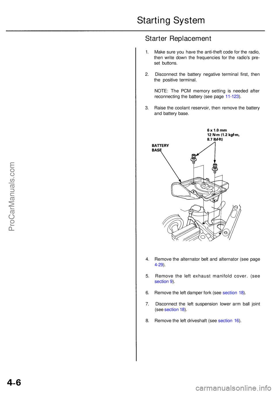
4. Remov e th e alternato r bel t an d alternato r (se e pag e
4-29).
5 . Remov e th e lef t exhaus t manifol d cover . (se e
sectio n 9 ).
6 . Remov e th e lef t dampe r for k (se e sectio n 18 ).
7 . Disconnec t th e lef t suspensio n lowe r ar m bal l join t
(se e sectio n 18 ).
8 . Remov e th e lef t driveshaf t (se e sectio n 16 ).
Starte r Replacemen t
1. Mak e sur e yo u hav e th e anti-thef t cod e fo r th e radio ,
the n writ e dow n th e frequencie s fo r th e radio' s pre -
se t buttons .
2 . Disconnec t th e batter y negativ e termina l first , the n
th e positiv e terminal .
NOTE : Th e PC M memor y settin g i s neede d afte r
reconnectin g th e batter y (se e pag e 11-123 ).
3 . Rais e th e coolan t reservoir , the n remov e th e batter y
an d batter y base .
Startin g Syste m
ProCarManuals.com
Page 328 of 1954
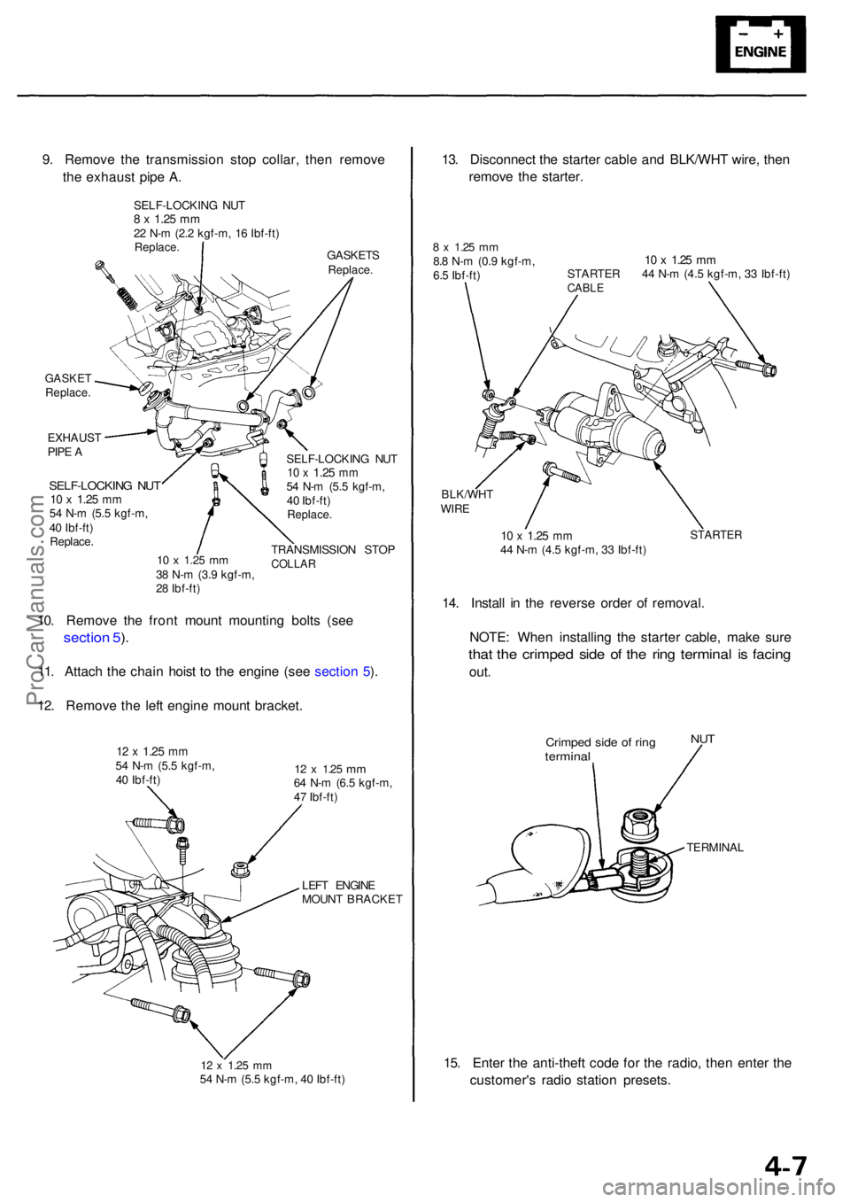
GASKETReplace .
EXHAUS T
PIP E A
SELF-LOCKIN G NU T10 x 1.2 5 mm54 N- m (5. 5 kgf-m ,
4 0 Ibf-ft )
Replace .
10 x 1.2 5 mm38 N- m (3. 9 kgf-m ,
2 8 Ibf-ft ) SELF-LOCKIN
G NU T
10 x 1.2 5 mm54 N- m (5. 5 kgf-m ,
4 0 Ibf-ft )
Replace .
TRANSMISSIO N STO PCOLLA R
10. Remov e th e fron t moun t mountin g bolt s (se e
sectio n 5 ).
11 . Attach the chai n hois t t o th e engine (see sectio n 5 ).
12 . Remov e th e lef t engin e moun t bracket .
12 x 1.2 5 mm54 N- m (5. 5 kgf-m ,
4 0 Ibf-ft )12 x 1.2 5 mm64 N- m (6. 5 kgf-m ,
4 7 Ibf-ft )
LEF T ENGIN E
MOUN T BRACKE T
12 x 1.2 5 mm54 N- m (5. 5 kgf-m , 4 0 Ibf-ft )
13. Disconnec t th e starte r cabl e an d BLK/WH T wire , the n
remov e th e starter .
8 x 1.2 5 mm8.8 N- m (0. 9 kgf-m ,
6. 5 Ibf-ft )10 x 1.2 5 mmSTARTE R 4 4 N- m (4. 5 kgf-m , 3 3 Ibf-ft )CABL E
BLK/WH TWIRE
10 x 1.2 5 mm44 N- m (4. 5 kgf-m , 3 3 Ibf-ft )STARTE R
14. Instal l i n th e revers e orde r o f removal .
NOTE : Whe n installin g th e starte r cable , mak e sur e
that th e crimpe d sid e o f th e rin g termina l i s facin g
out.
Crimpe d sid e o f rin gtermina l
NUT
TERMINA L
15. Ente r th e anti-theft code fo r th e radio , the n ente r th e
customer' s radi o statio n presets .
9
. Remov e th e transmissio n sto p collar , the n remov e
th e exhaus t pip e A .
GASKET SReplace.
SELF-LOCKIN G NU T8 x 1.2 5 mm22 N- m (2. 2 kgf-m , 1 6 Ibf-ft )Replace .
ProCarManuals.com
Page 348 of 1954
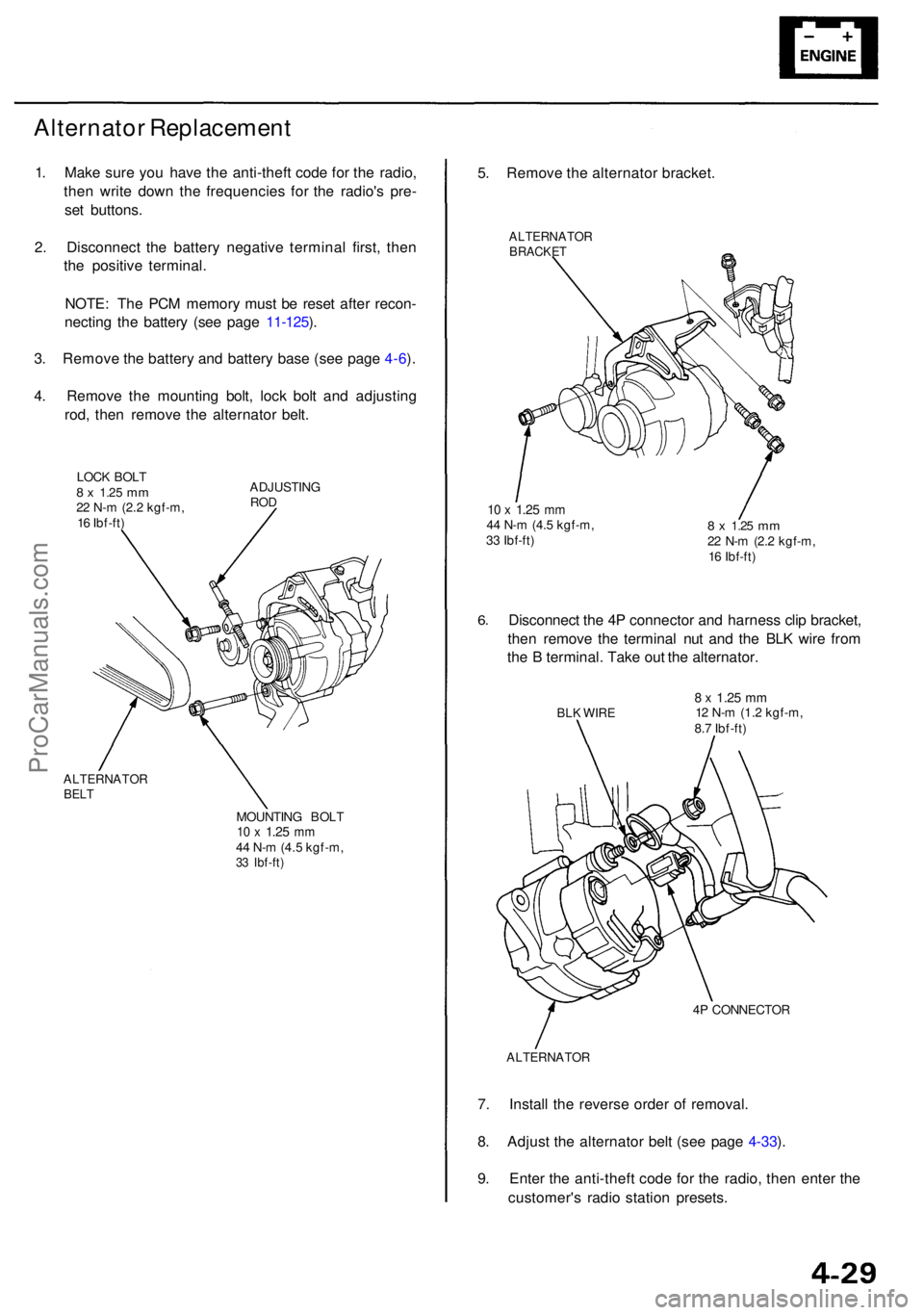
Alternator Replacemen t
1. Mak e sur e yo u hav e th e anti-thef t cod e fo r th e radio ,
the n writ e dow n th e frequencie s fo r th e radio' s pre -
se t buttons .
2 . Disconnec t th e batter y negativ e termina l first , the n
th e positiv e terminal .
NOTE : Th e PC M memor y mus t b e rese t afte r recon -
nectin g th e batter y (se e pag e 11-125 ).
3 . Remov e th e batter y an d batter y bas e (se e pag e 4-6 ).
4 . Remov e th e mountin g bolt , loc k bol t an d adjustin g
rod , the n remov e th e alternato r belt .
LOC K BOL T8 x 1.2 5 mm22 N- m (2. 2 kgf-m ,
1 6 Ibf-ft ) ADJUSTIN
GROD
ALTERNATO RBELT
MOUNTIN G BOL T10 x 1.2 5 mm44 N- m (4. 5 kgf-m ,33 Ibf-ft )
5. Remov e th e alternato r bracket .
ALTERNATO RBRACKET
10 x 1.2 5 mm44 N- m (4. 5 kgf-m ,
3 3 Ibf-ft )8 x 1.2 5 mm22 N- m (2. 2 kgf-m ,
1 6 Ibf-ft )
6.Disconnec t th e 4 P connecto r an d harnes s cli p bracket ,
the n remov e th e termina l nu t an d th e BL K wir e fro m
th e B terminal . Tak e ou t th e alternator .
BLK WIR E8 x 1.2 5 mm12 N- m (1.2 kgf-m ,
8. 7 Ibf-ft )
4 P CONNECTO R
ALTERNATO R
7. Instal l th e revers e orde r o f removal .
8 . Adjus t th e alternato r bel t (se e pag e 4-33 ).
9 . Ente r th e anti-thef t cod e fo r th e radio , the n ente r th e
customer' s radi o statio n presets .
ProCarManuals.com
Page 357 of 1954
Set/Resume/Cancel Switc h Test/Replacemen t
SRS component s ar e locate d in thi s area . Revie w th e SR S
componen t locations , precautions , an d procedure s i n th e
SR S (sectio n 24 ) befor e performin g repair s o r service .
1 . Mak e sur e yo u hav e th e anti-thef t cod e fo r th e radio ,
the n writ e dow n th e frequencie s fo r th e radio' s pre -
set buttons .
2. Disconnec t th e batter y negativ e cable , the n discon -
nec t th e positiv e cable , an d wai t a t leas t 3 minutes .
NOTE : Th e PC M memor y mus t b e rese t afte r recon -
necting th e batter y (se e pag e 11-125 ).
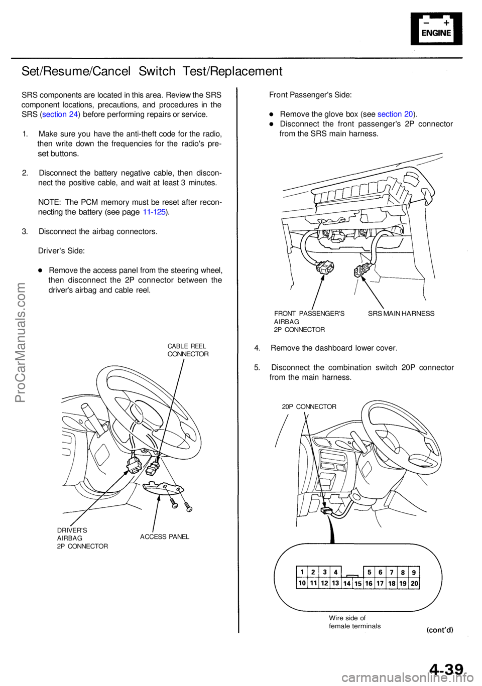
3 . Disconnec t th e airba g connectors .
Driver' s Side :
Remov e th e acces s pane l fro m th e steerin g wheel ,
the n disconnec t th e 2 P connecto r betwee n th e
driver' s airba g an d cabl e reel .
CABL E REE LCONNECTO R
DRIVER'SAIRBAG2P CONNECTO RACCES
S PANE L
Front Passenger' s Side :
Remov e th e glov e bo x (se e sectio n 20 ).
Disconnec t th e fron t passenger' s 2 P connecto r
fro m th e SR S mai n harness .
FRONT PASSENGER' SAIRBAG2P CONNECTO R
SRS MAI N HARNES S
4. Remov e th e dashboar d lowe r cover .
5 . Disconnec t th e combinatio n switc h 20 P connecto r
fro m th e mai n harness .
20P CONNECTO R
Wire sid e o ffemal e terminal s
ProCarManuals.com
Page 358 of 1954
Cruise Control
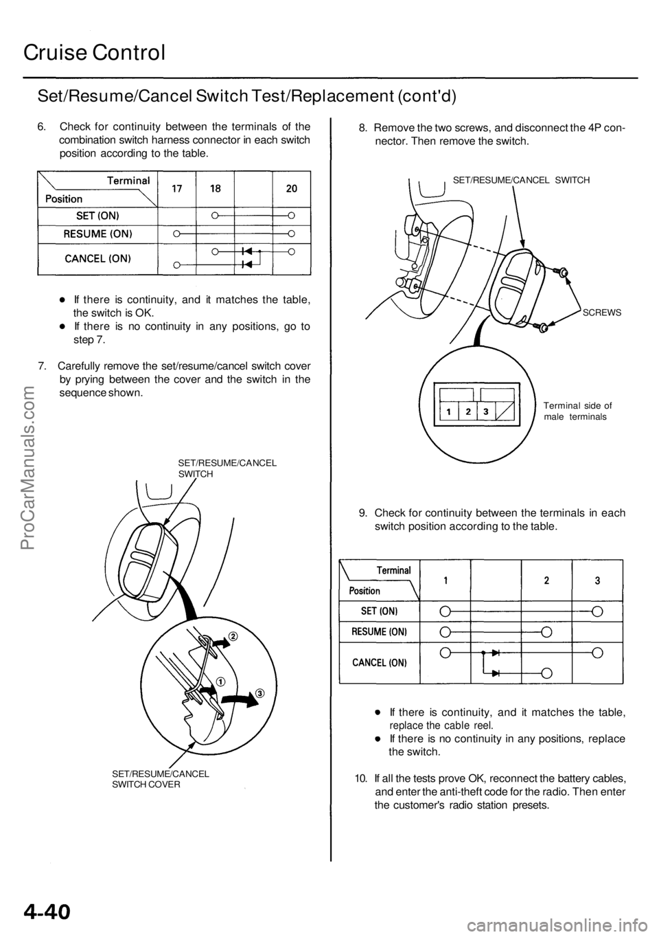
Set/Resume/Cancel Switch Test/Replacement (cont'd)
6. Check for continuity between the terminals of the
combination switch harness connector in each switch
position according to the table.
If there is continuity, and it matches the table,
the switch is OK.
If there is no continuity in any positions, go to
step 7.
7. Carefully remove the set/resume/cancel switch cover
by prying between the cover and the switch in the
sequence shown.
SET/RESUME/CANCEL
SWITCH
SET/RESUME/CANCEL
SWITCH COVER
8. Remove the two screws, and disconnect the 4P con-
nector. Then remove the switch.
SET/RESUME/CANCEL SWITCH
SCREWS
9. Check for continuity between the terminals in each
switch position according to the table.
If there is continuity, and it matches the table,
replace the cable reel.
If there is no continuity in any positions, replace
the switch.
10. If all the tests prove OK, reconnect the battery cables,
and enter the anti-theft code for the radio. Then enter
the customer's radio station presets.
Terminal side of
male terminalsProCarManuals.com
Page 365 of 1954
Engine Removal/Installatio n
Removal
Make sur e jack s an d safet y stand s ar e place d properl y
an d hois t bracket s ar e attache d to th e correc t position s
o n th e engine .
Mak e sur e th e vehicl e wil l no t rol l of f stand s an d fal l
whil e yo u ar e workin g unde r it .
CAUTION :
Us e fende r cover s t o avoi d damagin g painte d sur -
faces .
Unplu g th e wirin g connector s carefull y whil e holdin g
th e connecto r portio n to avoi d damage .
Mar k al l wirin g an d hose s t o avoi d misconnection .
Also , b e sur e tha t the y d o no t contac t othe r wirin g
o r hose s o r interfer e wit h othe r parts .
NOTE : D o th e PC M Memor y Settin g afte r reconnectin g
th e batter y (se e sectio n 11 ).
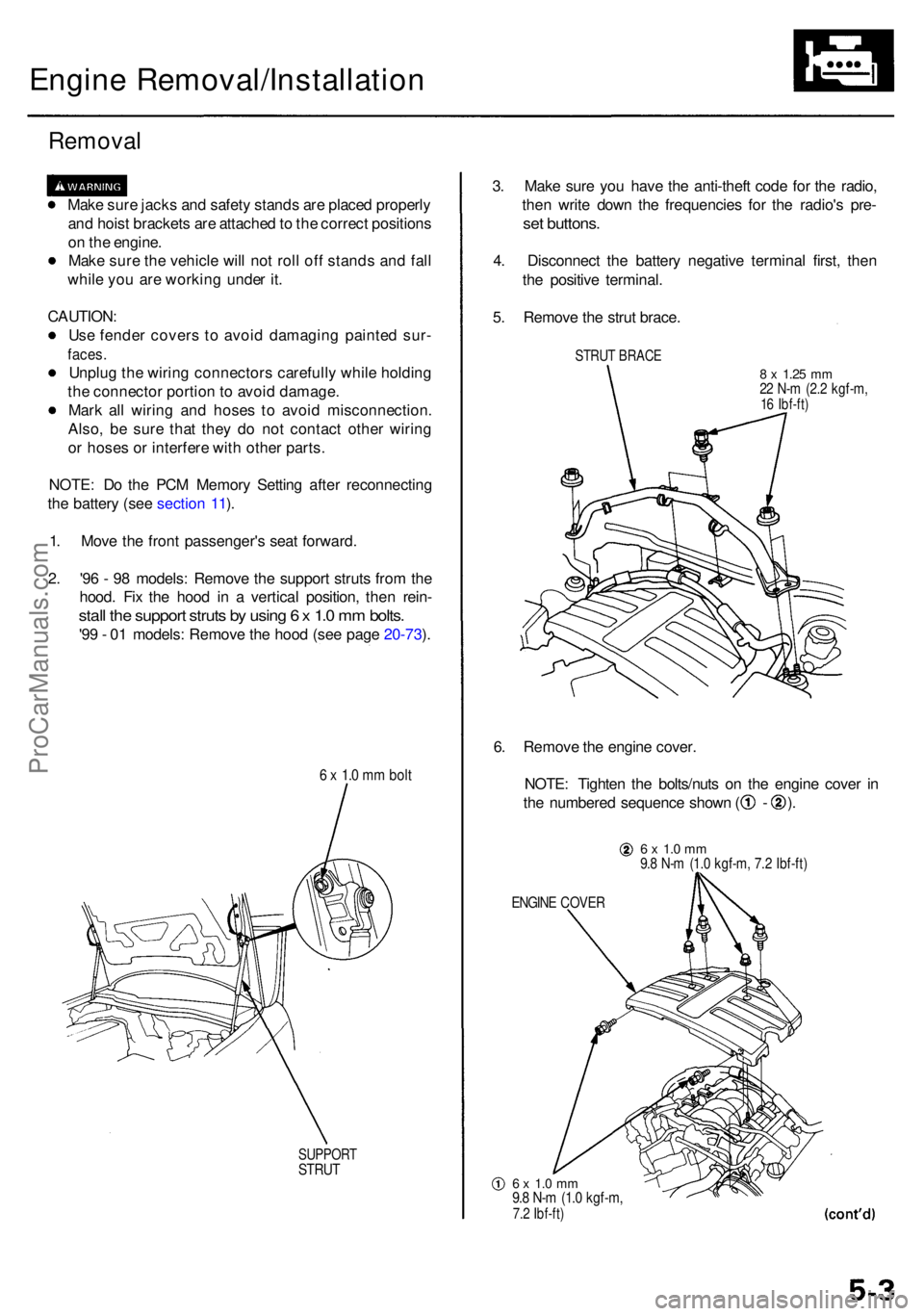
1 . Mov e th e fron t passenger' s sea t forward .
2 . '9 6 - 9 8 models : Remov e th e suppor t strut s fro m th e
hood . Fi x th e hoo d i n a vertica l position , the n rein -
stall th e suppor t strut s b y usin g 6 x 1. 0 m m bolts .
'99 - 0 1 models : Remov e th e hoo d (se e pag e 20-73 ).
6 x 1. 0 m m bol t
SUPPOR TSTRUT
3. Mak e sur e yo u hav e th e anti-thef t cod e fo r th e radio ,
the n writ e dow n th e frequencie s fo r th e radio' s pre -
set buttons .
4. Disconnec t th e batter y negativ e termina l first , the n
th e positiv e terminal .
5 . Remov e th e stru t brace .
STRUT BRAC E
8 x 1.2 5 mm22 N- m (2. 2 kgf-m ,16 Ibf-ft )
6. Remov e th e engin e cover .
NOTE : Tighte n th e bolts/nut s o n th e engin e cove r i n
th e numbere d sequenc e show n ( - ).
6 x 1. 0 m m9.8 N- m (1. 0 kgf-m , 7. 2 Ibf-ft )
ENGIN E COVE R
6 x 1. 0 m m9.8 N- m (1. 0 kgf-m ,7.2 Ibf-ft )
ProCarManuals.com