navigation update ACURA RL KA9 1996 Service Repair Manual
[x] Cancel search | Manufacturer: ACURA, Model Year: 1996, Model line: RL KA9, Model: ACURA RL KA9 1996Pages: 1954, PDF Size: 61.44 MB
Page 246 of 1954

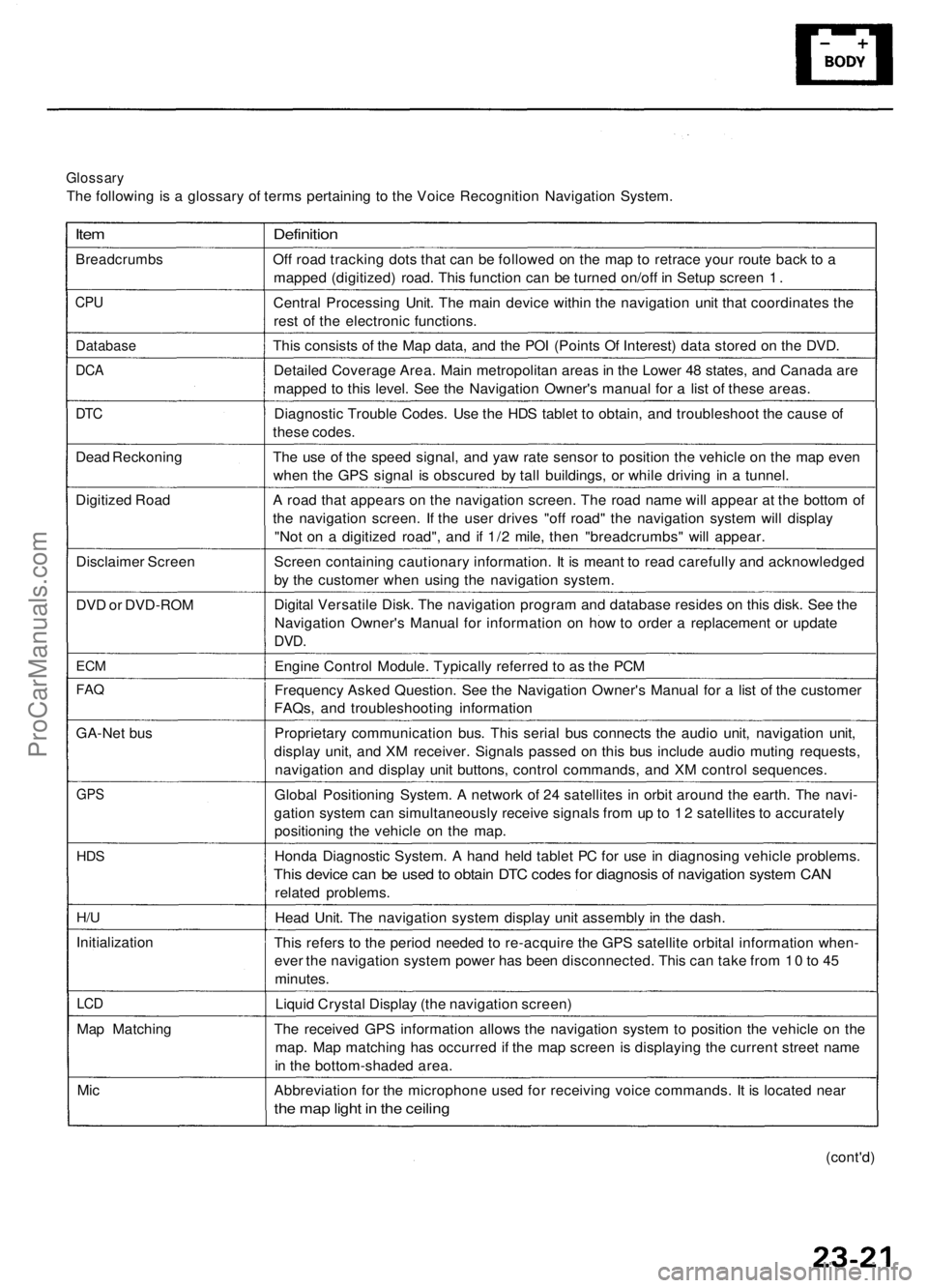
Glossary
The following is a glossary of terms pertaining to the Voice Recognition Navigation System.
Item
Breadcrumbs
CPU
Database
DCA
DTC
Dead Reckoning
Digitized Road
Disclaimer Screen
DVD or DVD-ROM
ECM
FAQ
GA-Net bus
GPS
HDS
H/U
Initialization
LCD
Map Matching
Mic
Definition
Off road tracking dots that can be followed on the map to retrace your route back to a
mapped (digitized) road. This function can be turned on/off in Setup screen 1.
Central Processing Unit. The main device within the navigation unit that coordinates the
rest of the electronic functions.
This consists of the Map data, and the POI (Points Of Interest) data stored on the DVD.
Detailed Coverage Area. Main metropolitan areas in the Lower 48 states, and Canada are
mapped to this level. See the Navigation Owner's manual for a list of these areas.
Diagnostic Trouble Codes. Use the HDS tablet to obtain, and troubleshoot the cause of
these codes.
The use of the speed signal, and yaw rate sensor to position the vehicle on the map even
when the GPS signal is obscured by tall buildings, or while driving in a tunnel.
A road that appears on the navigation screen. The road name will appear at the bottom of
the navigation screen. If the user drives "off road" the navigation system will display
"Not on a digitized road", and if 1/2 mile, then "breadcrumbs" will appear.
Screen containing cautionary information. It is meant to read carefully and acknowledged
by the customer when using the navigation system.
Digital Versatile Disk. The navigation program and database resides on this disk. See the
Navigation Owner's Manual for information on how to order a replacement or update
DVD.
Engine Control Module. Typically referred to as the PCM
Frequency Asked Question. See the Navigation Owner's Manual for a list of the customer
FAQs, and troubleshooting information
Proprietary communication bus. This serial bus connects the audio unit, navigation unit,
display unit, and XM receiver. Signals passed on this bus include audio muting requests,
navigation and display unit buttons, control commands, and XM control sequences.
Global Positioning System. A network of 24 satellites in orbit around the earth. The navi-
gation system can simultaneously receive signals from up to 12 satellites to accurately
positioning the vehicle on the map.
Honda Diagnostic System. A hand held tablet PC for use in diagnosing vehicle problems.
This device can be used to obtain DTC codes for diagnosis of navigation system CAN
related problems.
Head Unit. The navigation system display unit assembly in the dash.
This refers to the period needed to re-acquire the GPS satellite orbital information when-
ever the navigation system power has been disconnected. This can take from 10 to 45
minutes.
Liquid Crystal Display (the navigation screen)
The received GPS information allows the navigation system to position the vehicle on the
map. Map matching has occurred if the map screen is displaying the current street name
in the bottom-shaded area.
Abbreviation for the microphone used for receiving voice commands. It is located near
the map light in the ceiling
(cont'd)ProCarManuals.com
Page 271 of 1954

Navigation Syste m
System Diagnosi s Mod e (cont'd )
GPS Informatio n
This scree n show s th e curren t statu s o f GP S reception .
Th e circula r diagra m show s th e curren t locatio n o f th e
GP S satellite s (yello w numbers ) a s the y woul d appea r i n
th e sky . Th e oute r circl e represent s th e horizo n ( 0 degree s
elevation) . Th e middl e an d inne r circle s represent s 3 0
an d 6 0 degree s respectively . Th e ver y cente r o f th e dia -
gra m (9 0 degree s elevation ) i s directl y overhead .
Naturally, nearb y obstructions , lik e tal l building s wil l
bloc k satellite s i n tha t direction . Tha t i s wh y i t i s neces -
sar y t o b e i n a n ope n are a t o effectivel y troubleshoo t
GP S receptio n issues .
The satellit e number s show n o n th e diagra m corre -
spond t o th e "PRN " numbe r i n th e "GP S Details "
screen . Ther e ar e alway s 2 4 "active " GP S satellite s in
orbit . Becaus e satellite s fail , an d hav e t o b e remove d
fro m service , spare s ar e alway s parke d in orbit , read y t o
b e activated . Thi s is wh y th e PR N (satellit e ID number )
can be greate r tha n 24 .
NOTE : T o us e thi s scree n fo r troubleshooting , th e vehi -
cl e shoul d b e ou t sid e awa y fro m buildings , tal l trees ,
an d high-tensio n wire s fo r a t leas t 1 0 minute s wit h th e
engin e running . Also , mak e sur e th e rea r shel f i s fre e o f
loos e item s tha t ca n bloc k receptio n an d tha t th e trun k
li d is closed .
• Th e "Numbe r o f Satellites " bo x show s th e numbe r o f
acquire d satellite s (maximu m o f 12) . I t shoul d contai n
3 o r mor e icons . I f no t troubleshoo t fo r "GP S ico n i s
white " (se e pag e 23-32 ).
• Th e "Curren t Position " show s latitude , longitude , an d
elevatio n (i n meters) . I f ther e ar e les s tha n 3 satel -
lites , th e elevatio n ca n b e grossl y inaccurate .
• Th e Date/Tim e fiel d show s th e curren t date , an d als o
a tim e tha t include s dayligh t saving s an d othe r off -
set s entere d b y th e custome r i n Setu p scree n 2
"Adjus t Tim e Zone/Clock" .
GPS Detai l
By pressin g an d holdin g th e MEN U butto n fo r 1 0 sec -
onds , a GP S Detai l scree n is displayed . Thi s scree n dis -
play s rea l tim e incomin g satellit e positiona l data . Mos t
o f th e informatio n show n o n thi s scree n i s fo r factor y
use , howeve r som e o f th e dat a ca n indicat e partia l GP S
signa l interference .
• Th e bo x TS/A S an d HDop/VDo p is fo r factor y use .
• Th e Spee d an d Directio n informatio n i s update d i n
rea l tim e whe n driving , an d ca n b e use d t o detec t
intermitten t spee d senso r problems .
• Th e Date/Tim e Informatio n i s th e sam e a s i n Setu p
scree n 2 "Adjus t Tim e Zone/Clock" .
• I f th e "3D " ico n i s show n abov e th e yello w dots , thi s
implie s tha t a t leas t 4 satellite s ar e availabl e fo r ma p
positioning , an d th e "GPS " indicator on th e ma p
scree n wil l b e green . Se e th e "Globa l Positionin g
System " detaile d explanatio n i n th e "Syste m
Description" .
• I f th e ro w o f dat a i n th e tabl e belo w begin s wit h a
"yello w dot" , th e AZ I an d E L field s ca n b e use d t o
locat e eac h satellit e o n th e circula r GP S diagra m (se e
prio r screen) .
NOTE : Th e dat a belo w is a n exampl e only .
Th e tabl e o f value s show n o n th e scree n belo w ha s th e
followin g columns :
If "3D " i s missing , fol -
lo w troubleshootin g
(see pag e 23-32 ).
If al l 0 , then , follo w
troubleshootin g (se e
page 23-32 ).
ProCarManuals.com
Page 275 of 1954

Navigation System
System Diagnosis Mode (cont'd)
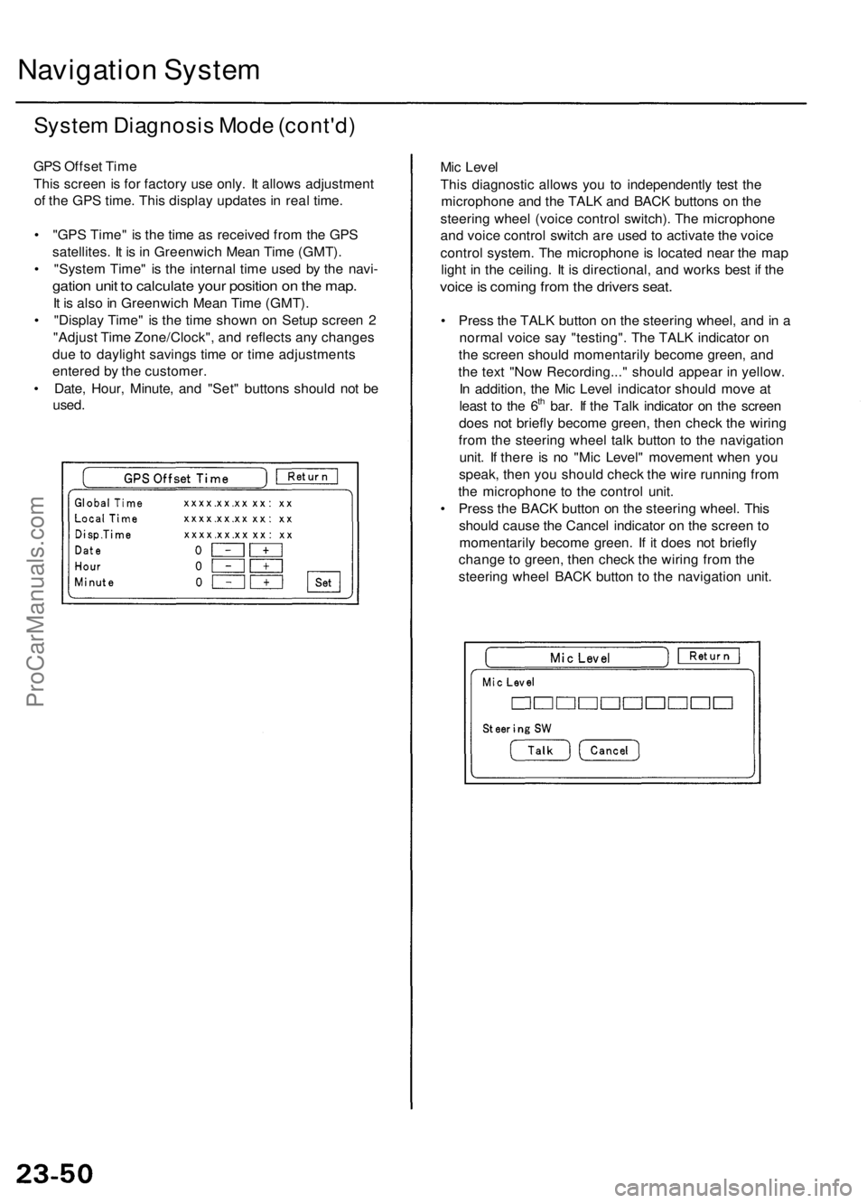
GPS Offset Time
This screen is for factory use only. It allows adjustment
of the GPS time. This display updates in real time.
• "GPS Time" is the time as received from the GPS
satellites. It is in Greenwich Mean Time (GMT).
• "System Time" is the internal time used by the navi-
gation unit to calculate your position on the map.
It is also in Greenwich Mean Time (GMT).
• "Display Time" is the time shown on Setup screen 2
"Adjust Time Zone/Clock", and reflects any changes
due to daylight savings time or time adjustments
entered by the customer.
• Date, Hour, Minute, and "Set" buttons should not be
used.
Mic Level
This diagnostic allows you to independently test the
microphone and the TALK and BACK buttons on the
steering wheel (voice control switch). The microphone
and voice control switch are used to activate the voice
control system. The microphone is located near the map
light in the ceiling. It is directional, and works best if the
voice is coming from the drivers seat.
• Press the TALK button on the steering wheel, and in a
normal voice say "testing". The TALK indicator on
the screen should momentarily become green, and
the text "Now Recording..." should appear in yellow.
In addition, the Mic Level indicator should move at
least to the 6th bar. If the Talk indicator on the screen
does not briefly become green, then check the wiring
from the steering wheel talk button to the navigation
unit. If there is no "Mic Level" movement when you
speak, then you should check the wire running from
the microphone to the control unit.
• Press the BACK button on the steering wheel. This
should cause the Cancel indicator on the screen to
momentarily become green. If it does not briefly
change to green, then check the wiring from the
steering wheel BACK button to the navigation unit.ProCarManuals.com