oil type ACURA RL KA9 1996 Service Repair Manual
[x] Cancel search | Manufacturer: ACURA, Model Year: 1996, Model line: RL KA9, Model: ACURA RL KA9 1996Pages: 1954, PDF Size: 61.44 MB
Page 309 of 1954
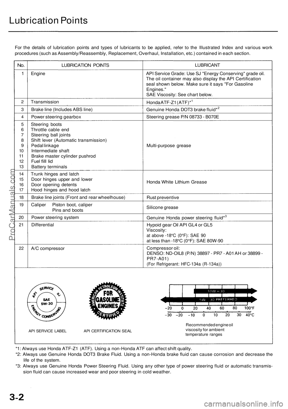
Lubrication Points
For the details of lubrication points and types of lubricants to be applied, refer to the Illustrated Index and various work
procedures (such as Assembly/Reassembly, Replacement, Overhaul, Installation, etc.) contained in each section.
No.
1
2
3
4
5
6
7
8
9
10
11
12
13
14
15
16
17
18
19
20
21
22
LUBRICATION POINTS
Engine
Transmission
Brake line (Includes ABS line)
Power steering gearbox
Steering boots
Throttle cable end
Steering ball joints
Shift lever (Automatic transmission)
Pedal linkage
Intermediate shaft
Brake master cylinder pushrod
Fuel
fill
lid
Battery terminals
Trunk hinges and latch
Door hinges upper and lower
Door opening detents
Hood hinges and hood latch
Brake line joints (Front and rear wheelhouse)
Caliper Piston boot, caliper
Pins and boots
Power steering system
Differential
A/C compressor
API SERVICE LABEL API CERTIFICATION SEAL
LUBRICANT
API Service Grade: Use SJ "Energy Conserving" grade oil.
The oil container may also display the API Certification
seal shown below. Make sure it says "For Gasoline
Engines."
SAE Viscosity: See chart below.
Honda ATF-Z1 (ATF)*1
Genuine Honda DOT3 brake fluid*2
Steering grease P/N 08733 - B070E
Multi-purpose grease
Honda White Lithium Grease
Rust preventive
Silicone grease
Genuine Honda power steering fluid*3
Hypoid gear Oil API GL4 or GL5
Viscosity:
at above -18°C (0°F): SAE 90
at less than -18°C (0°F): SAE 80W-90
Compressor oil:
DENSO: ND-OIL8 (P/N) 38897 - PR7 - A01 AH or 38899 -
PR7-A01)
(For Refrigerant: HFC-134a (R-134a))
Recommended engine oil
viscosity for ambient
temperature ranges
*1: Always use Honda ATF-Z1 (ATF). Using a non-Honda ATF can affect shift quality.
*2: Always use Genuine Honda DOT3 Brake Fluid. Using a non-Honda brake fluid can cause corrosion and decrease the
life of the system.
*3: Always use Genuine Honda Power Steering Fluid. Using any other type of power steering fluid or automatic transmis-
sion fluid can cause increased wear and poor steering in cold weather.ProCarManuals.com
Page 426 of 1954
Cylinder Heads
Installation (cont'd)
4. Install the cylinder heads on the cylinder block.
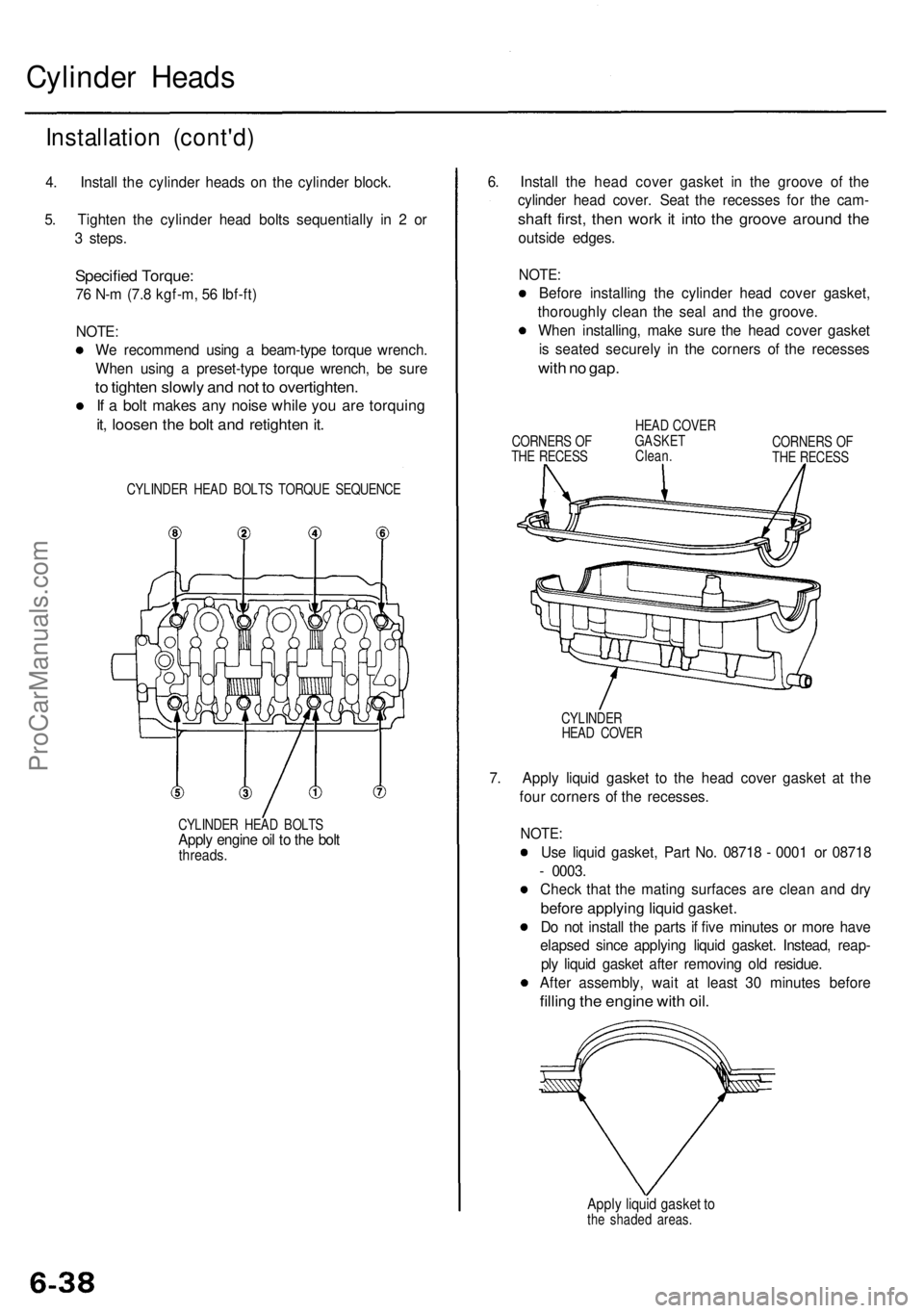
5. Tighten the cylinder head bolts sequentially in 2 or
3 steps.
Specified Torque:
76 N-m (7.8 kgf-m, 56 Ibf-ft)
NOTE:
We recommend using a beam-type torque wrench.
When using a preset-type torque wrench, be sure
to tighten slowly and not to overtighten.
If a bolt makes any noise while you are torquing
it, loosen the bolt and retighten it.
CYLINDER HEAD BOLTS TORQUE SEQUENCE
CYLINDER HEAD BOLTS
Apply engine oil to the bolt
threads.
6. Install the head cover gasket in the groove of the
cylinder head cover. Seat the recesses for the cam-
shaft first, then work it into the groove around the
outside edges.
NOTE:
Before installing the cylinder head cover gasket,
thoroughly clean the seal and the groove.
When installing, make sure the head cover gasket
is seated securely in the corners of the recesses
with no gap.
CORNERS OF
THE RECESS
HEAD COVER
GASKET
Clean.
CORNERS OF
THE RECESS
CYLINDER
HEAD COVER
7. Apply liquid gasket to the head cover gasket at the
four corners of the recesses.
NOTE:
Use liquid gasket, Part No. 08718 - 0001 or 08718
- 0003.
Check that the mating surfaces are clean and dry
before applying liquid gasket.
Do not install the parts if five minutes or more have
elapsed since applying liquid gasket. Instead, reap-
ply liquid gasket after removing old residue.
After assembly, wait at least 30 minutes before
filling the engine with oil.
Apply liquid gasket to
the shaded areas.ProCarManuals.com
Page 440 of 1954
Crankshaft
Inspection
• Clean the crankshaft oil passages with pipe cleaners
or a suitable brush.
• Check the keyway and threads.
Alignment
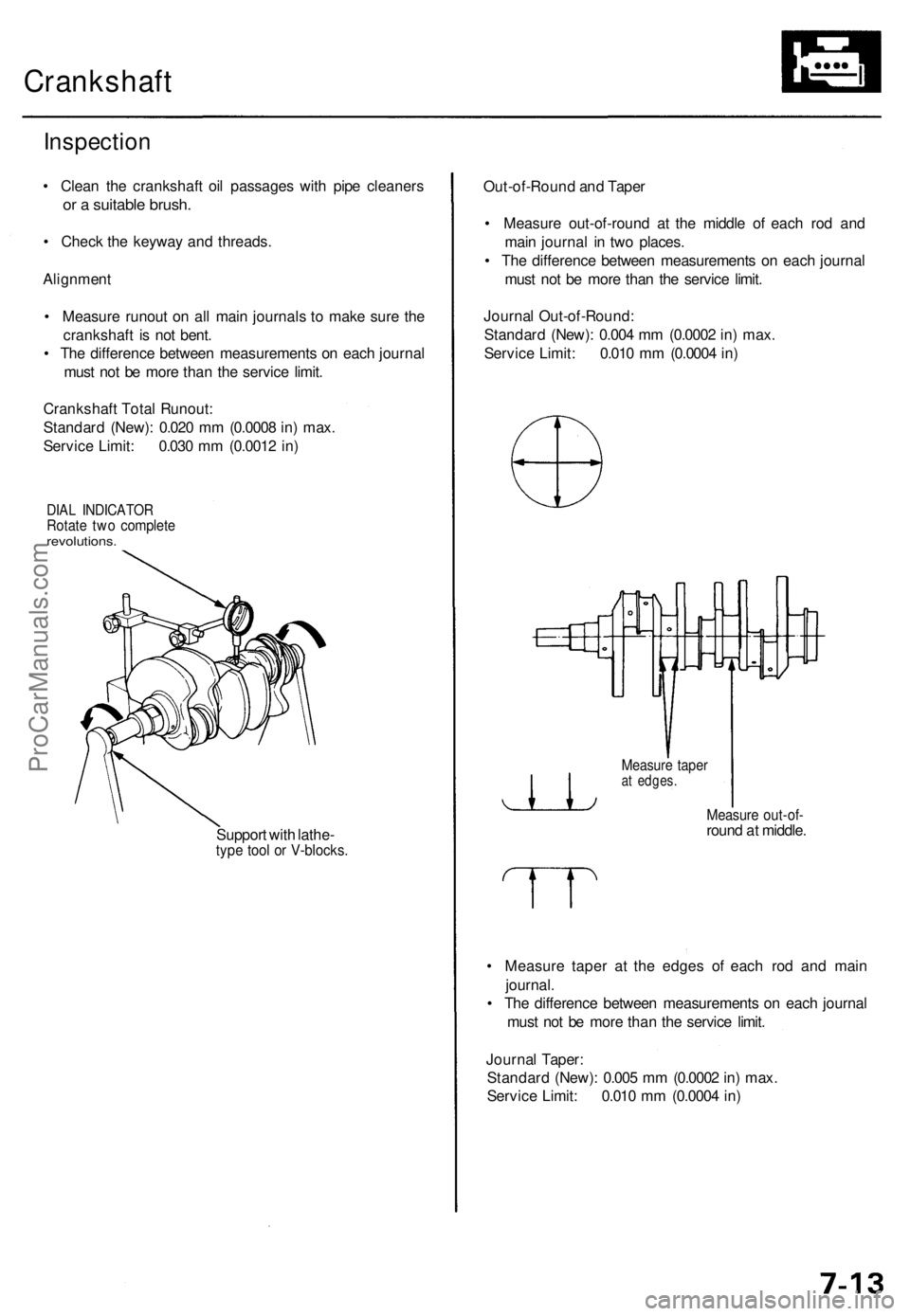
• Measure runout on all main journals to make sure the
crankshaft is not bent.
• The difference between measurements on each journal
must not be more than the service limit.
Crankshaft Total Runout:
Standard (New): 0.020 mm (0.0008 in) max.
Service Limit: 0.030 mm (0.0012 in)
DIAL INDICATOR
Rotate two complete
revolutions.
Support with lathe-
type tool or V-blocks.
Out-of-Round and Taper
• Measure out-of-round at the middle of each rod and
main journal in two places.
• The difference between measurements on each journal
must not be more than the service limit.
Journal Out-of-Round:
Standard (New): 0.004 mm (0.0002 in) max.
Service Limit: 0.010 mm (0.0004 in)
Measure taper
at edges.
Measure out-of-
round at middle.
• Measure taper at the edges of each rod and main
journal.
• The difference between measurements on each journal
must not be more than the service limit.
Journal Taper:
Standard (New): 0.005 mm (0.0002 in) max.
Service Limit: 0.010 mm (0.0004 in)ProCarManuals.com
Page 646 of 1954
Fuel Suppl y Syste m
Fuel Gaug e (cont'd )
6. Tur n th e ignitio n switc h OFF .
7 . Attac h a jumpe r wir e betwee n th e No . 1 an d No . 2
terminals , the n tur n th e ignitio n switc h O N (II) .
8 . Chec k tha t th e pointe r o f th e fue l gaug e start s mov -
ing towar d th e "F " mark .
CAUTION : Tur n th e ignitio n switc h OF F befor e th e
pointe r reache s "F " o n th e gaug e dial . Failur e to d o
s o ma y damag e th e fue l gauge .
NOTE : Th e fue l gaug e is a bobbi n (cross-coil )
type,
henc e th e fue l leve l i s continuousl y indicate d eve n
whe n th e ignitio n switc h i s OFF , an d th e pointe r
moves mor e slowl y tha n tha t o f a bimeta l type .
• I f th e pointe r o f th e fue l gaug e doe s no t mov e a t
all , replac e th e gauge .
• I f th e gaug e i s OK , inspec t th e fue l gaug e send -
ing unit .
ProCarManuals.com
Page 1156 of 1954
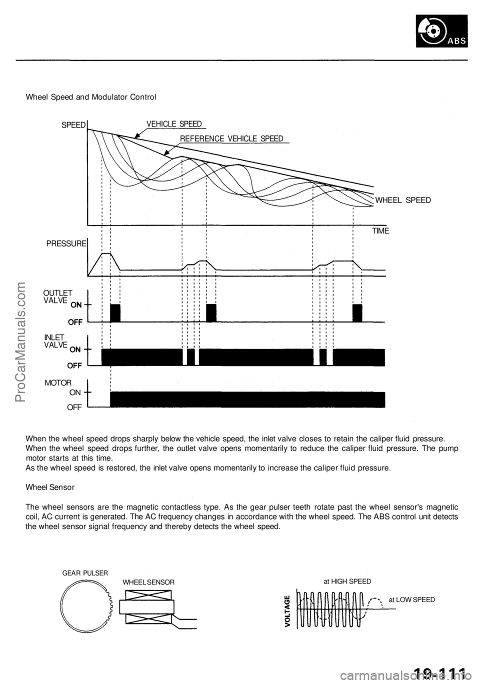
Wheel Spee d an d Modulato r Contro l
SPEED VEHICL E SPEE D
REFERENC E VEHICL E SPEE D
PRESSUR E
OUTLETVALVE
INLETVALV E
MOTO R
ON
OF F
WHEE L SPEE D
TIM E
Whe n th e whee l spee d drop s sharpl y belo w th e vehicl e speed , th e inle t valv e close s t o retai n th e calipe r flui d pressure .
Whe n th e whee l spee d drop s further , th e outle t valv e open s momentaril y t o reduc e th e calipe r flui d pressure . Th e pum p
moto r start s a t thi s time .
A s th e whee l spee d i s restored , th e inle t valv e open s momentaril y t o increas e th e calipe r flui d pressure .
Whee l Senso r
Th e whee l sensor s ar e th e magneti c contactles s type . A s th e gea r pulse r teet h rotat e pas t th e whee l sensor' s magnetic
coil , A C curren t i s generated . Th e A C frequenc y change s i n accordanc e wit h th e whee l speed . Th e AB S contro l uni t detect s
th e whee l senso r signa l frequenc y an d thereb y detect s th e whee l speed .
GEAR PULSE R
WHEEL SENSO R a
t HIG H SPEE D
at LO W SPEE D
ProCarManuals.com