service indicator ACURA RL KA9 1996 Service Repair Manual
[x] Cancel search | Manufacturer: ACURA, Model Year: 1996, Model line: RL KA9, Model: ACURA RL KA9 1996Pages: 1954, PDF Size: 61.44 MB
Page 45 of 1954

Description
Basic operation:
1. OnStar system is activated.
2. Data is transmitted to service provider.
GPS SATELLITES
Two-way cellular communication
with call center.
Dispatch
Rescue/Police
911 CALL
CENTER
3. Call center associate makes appropriate response:
— Accident/Emergency notification (Police, Fire and EMS, etc.)
— Airbag deployment (Accident)
— Roadside assistance
— Stolen vehicle tracking
— Remote door lock/unlock command
— Misplaced vehicle (Flashes parking lights/honks horn)
— Route guidance
— Ride Assist
— Concierge services/convenience
Buttons and indicator:
DOT BUTTON
ONSTAR INDICATOR
Solid Green Light: System OK
Flashing Green Light: Call in
progress
Solid Red Light: System
malfunction
Flashing Red Light: Call
in progress, but malfunction
in system exist.
ONSTAR BUTTON
EMERGENCY BUTTON
Activation and termination
of voice recognition
(VR) for virtual advisor and cellular phone.
Used to connect to call
center (voice based information
service).
Used for emergencies.
Emergency calls have priority
over all others.
ONSTAR CALL
CENTER
(Human Advisor)
Requests for
dispatchProCarManuals.com
Page 47 of 1954
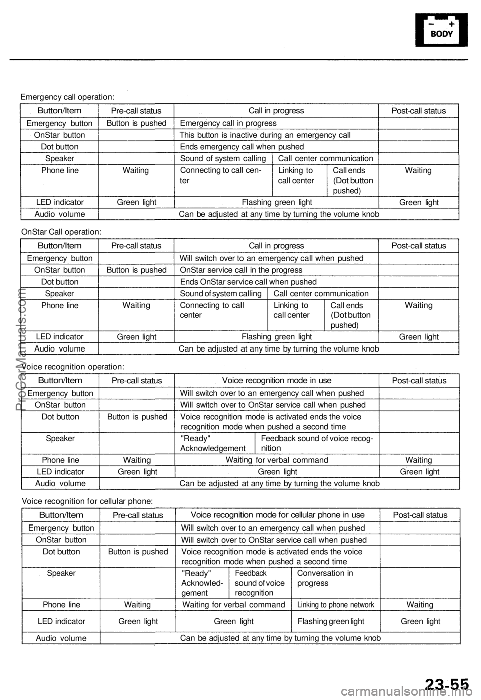
Emergency call operation:
Button/Item
Emergency button
OnStar button
Dot button
Speaker
Phone line
LED indicator
Audio volume
Pre-call status
Button is pushed
Waiting
Green light
Call in progress
Emergency call in progress
This button is inactive during an emergency call
Ends emergency call when pushed
Sound of system calling
Connecting to call cen-
ter
Call center communication
Linking to
call center
Flashing green light
Call ends
(Dot button
pushed)
Post-call status
Waiting
Green light
Can be adjusted at any time by turning the volume knob
OnStar Call operation:
Button/Item
Emergency button
OnStar button
Dot button
Speaker
Phone line
LED indicator
Audio volume
Pre-call status
Button is pushed
Waiting
Green light
Call in progress
Will switch over to an emergency call when pushed
OnStar service call in the progress
Ends OnStar service call when pushed
Sound of system calling
Connecting to call
center
Call center communication
Linking to
call center
Call ends
(Dot button
pushed)
Flashing green light
Post-call status
Waiting
Green light
Can be adjusted at any time by turning the volume knob
Voice recognition operation:
Button/Item
Emergency button
OnStar button
Dot button
Speaker
Phone line
LED indicator
Audio volume
Pre-call status
Button is pushed
Waiting
Green light
Voice recognition mode in use
Will switch over to an emergency call when pushed
Will switch over to OnStar service call when pushed
Voice recognition mode is activated ends the voice
recognition mode when pushed a second time
"Ready"
Acknowledgement
Waiting
Feedback sound of voice recog-
nition
for verbal command
Green light
Post-call status
Waiting
Green light
Can be adjusted at any time by turning the volume knob
Voice recognition for cellular phone:
Button/Item
Emergency button
OnStar button
Dot button
Speaker
Phone line
LED indicator
Audio volume
Pre-call status
Button is pushed
Waiting
Green light
Voice recognition mode for cellular phone in use
Will switch over to an emergency call when pushed
Will switch over to OnStar service call when pushed
Voice recognition mode is activated ends the voice
recognition mode when pushed a second time
"Ready"
Acknowled-
gement
Feedback
sound of voice
recognition
Waiting for verbal command
Green light
Conversation in
progress
Linking to phone network
Flashing green light
Post-call status
Waiting
Green light
Can be adjusted at any time by turning the volume knobProCarManuals.com
Page 271 of 1954

Navigation Syste m
System Diagnosi s Mod e (cont'd )
GPS Informatio n
This scree n show s th e curren t statu s o f GP S reception .
Th e circula r diagra m show s th e curren t locatio n o f th e
GP S satellite s (yello w numbers ) a s the y woul d appea r i n
th e sky . Th e oute r circl e represent s th e horizo n ( 0 degree s
elevation) . Th e middl e an d inne r circle s represent s 3 0
an d 6 0 degree s respectively . Th e ver y cente r o f th e dia -
gra m (9 0 degree s elevation ) i s directl y overhead .
Naturally, nearb y obstructions , lik e tal l building s wil l
bloc k satellite s i n tha t direction . Tha t i s wh y i t i s neces -
sar y t o b e i n a n ope n are a t o effectivel y troubleshoo t
GP S receptio n issues .
The satellit e number s show n o n th e diagra m corre -
spond t o th e "PRN " numbe r i n th e "GP S Details "
screen . Ther e ar e alway s 2 4 "active " GP S satellite s in
orbit . Becaus e satellite s fail , an d hav e t o b e remove d
fro m service , spare s ar e alway s parke d in orbit , read y t o
b e activated . Thi s is wh y th e PR N (satellit e ID number )
can be greate r tha n 24 .
NOTE : T o us e thi s scree n fo r troubleshooting , th e vehi -
cl e shoul d b e ou t sid e awa y fro m buildings , tal l trees ,
an d high-tensio n wire s fo r a t leas t 1 0 minute s wit h th e
engin e running . Also , mak e sur e th e rea r shel f i s fre e o f
loos e item s tha t ca n bloc k receptio n an d tha t th e trun k
li d is closed .
• Th e "Numbe r o f Satellites " bo x show s th e numbe r o f
acquire d satellite s (maximu m o f 12) . I t shoul d contai n
3 o r mor e icons . I f no t troubleshoo t fo r "GP S ico n i s
white " (se e pag e 23-32 ).
• Th e "Curren t Position " show s latitude , longitude , an d
elevatio n (i n meters) . I f ther e ar e les s tha n 3 satel -
lites , th e elevatio n ca n b e grossl y inaccurate .
• Th e Date/Tim e fiel d show s th e curren t date , an d als o
a tim e tha t include s dayligh t saving s an d othe r off -
set s entere d b y th e custome r i n Setu p scree n 2
"Adjus t Tim e Zone/Clock" .
GPS Detai l
By pressin g an d holdin g th e MEN U butto n fo r 1 0 sec -
onds , a GP S Detai l scree n is displayed . Thi s scree n dis -
play s rea l tim e incomin g satellit e positiona l data . Mos t
o f th e informatio n show n o n thi s scree n i s fo r factor y
use , howeve r som e o f th e dat a ca n indicat e partia l GP S
signa l interference .
• Th e bo x TS/A S an d HDop/VDo p is fo r factor y use .
• Th e Spee d an d Directio n informatio n i s update d i n
rea l tim e whe n driving , an d ca n b e use d t o detec t
intermitten t spee d senso r problems .
• Th e Date/Tim e Informatio n i s th e sam e a s i n Setu p
scree n 2 "Adjus t Tim e Zone/Clock" .
• I f th e "3D " ico n i s show n abov e th e yello w dots , thi s
implie s tha t a t leas t 4 satellite s ar e availabl e fo r ma p
positioning , an d th e "GPS " indicator on th e ma p
scree n wil l b e green . Se e th e "Globa l Positionin g
System " detaile d explanatio n i n th e "Syste m
Description" .
• I f th e ro w o f dat a i n th e tabl e belo w begin s wit h a
"yello w dot" , th e AZ I an d E L field s ca n b e use d t o
locat e eac h satellit e o n th e circula r GP S diagra m (se e
prio r screen) .
NOTE : Th e dat a belo w is a n exampl e only .
Th e tabl e o f value s show n o n th e scree n belo w ha s th e
followin g columns :
If "3D " i s missing , fol -
lo w troubleshootin g
(see pag e 23-32 ).
If al l 0 , then , follo w
troubleshootin g (se e
page 23-32 ).
ProCarManuals.com
Page 410 of 1954
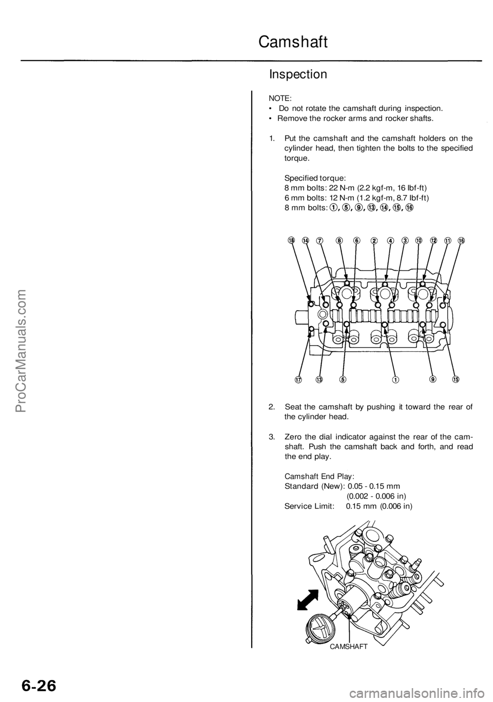
Camshaft
Inspection
NOTE:
• Do not rotate the camshaft during inspection.
• Remove the rocker arms and rocker shafts.
1. Put the camshaft and the camshaft holders on the
cylinder head, then tighten the bolts to the specified
torque.
Specified torque:
8 mm bolts: 22 N-m (2.2 kgf-m, 16 Ibf-ft)
6 mm bolts: 12 N-m (1.2 kgf-m, 8.7 Ibf-ft)
8 mm bolts:
2. Seat the camshaft by pushing it toward the rear of
the cylinder head.
3. Zero the dial indicator against the rear of the cam-
shaft. Push the camshaft back and forth, and read
the end play.
Camshaft End Play:
Standard (New): 0.05 - 0.15 mm
(0.002 - 0.006 in)
Service Limit: 0.15 mm (0.006 in)
CAMSHAFTProCarManuals.com
Page 440 of 1954
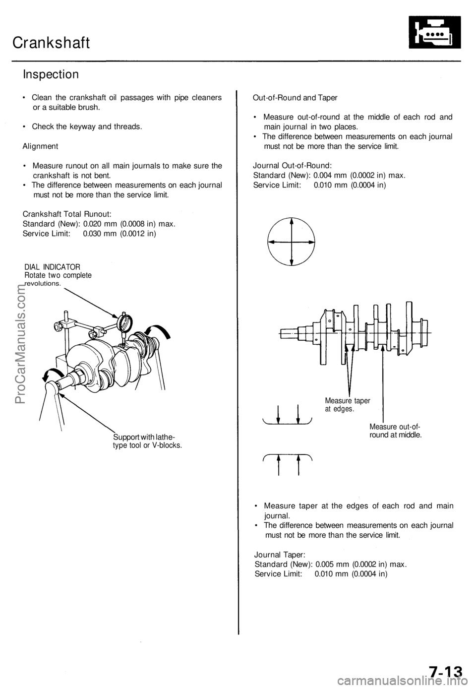
Crankshaft
Inspection
• Clean the crankshaft oil passages with pipe cleaners
or a suitable brush.
• Check the keyway and threads.
Alignment
• Measure runout on all main journals to make sure the
crankshaft is not bent.
• The difference between measurements on each journal
must not be more than the service limit.
Crankshaft Total Runout:
Standard (New): 0.020 mm (0.0008 in) max.
Service Limit: 0.030 mm (0.0012 in)
DIAL INDICATOR
Rotate two complete
revolutions.
Support with lathe-
type tool or V-blocks.
Out-of-Round and Taper
• Measure out-of-round at the middle of each rod and
main journal in two places.
• The difference between measurements on each journal
must not be more than the service limit.
Journal Out-of-Round:
Standard (New): 0.004 mm (0.0002 in) max.
Service Limit: 0.010 mm (0.0004 in)
Measure taper
at edges.
Measure out-of-
round at middle.
• Measure taper at the edges of each rod and main
journal.
• The difference between measurements on each journal
must not be more than the service limit.
Journal Taper:
Standard (New): 0.005 mm (0.0002 in) max.
Service Limit: 0.010 mm (0.0004 in)ProCarManuals.com
Page 728 of 1954
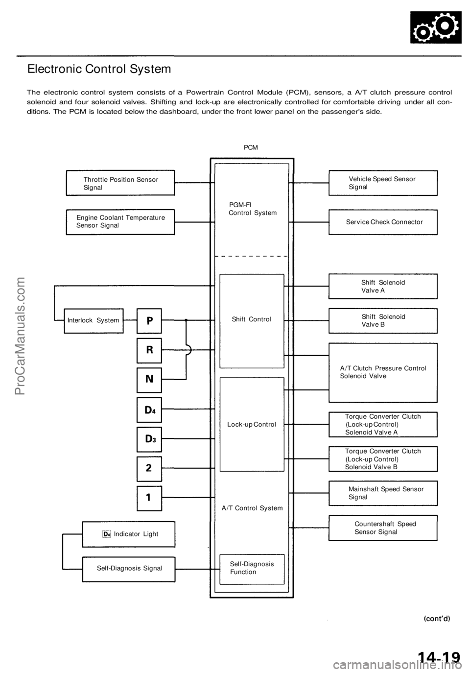
Electronic Control System
The electronic control system consists of a Powertrain Control Module (PCM), sensors, a A/T clutch pressure control
solenoid and four solenoid valves. Shifting and lock-up are electronically controlled for comfortable driving under all con-
ditions. The PCM is located below the dashboard, under the front lower panel on the passenger's side.
PCM
Throttle Position Sensor
Signal
Engine Coolant Temperature
Sensor Signal
Indicator Light
Self-Diagnosis Signal
PGM-FI
Control System
Shift Control
Lock-up Control
A/T Control System
Self-Diagnosis
Function
Vehicle Speed Sensor
Signal
Service Check Connector
Shift Solenoid
Valve A
Shift Solenoid
Valve B
A/T Clutch Pressure Control
Solenoid Valve
Torque Converter Clutch
(Lock-up Control)
Solenoid Valve A
Torque Converter Clutch
(Lock-up Control)
Solenoid Valve B
Mainshaft Speed Sensor
Signal
Countershaft Speed
Sensor Signal
Interlock SystemProCarManuals.com
Page 803 of 1954
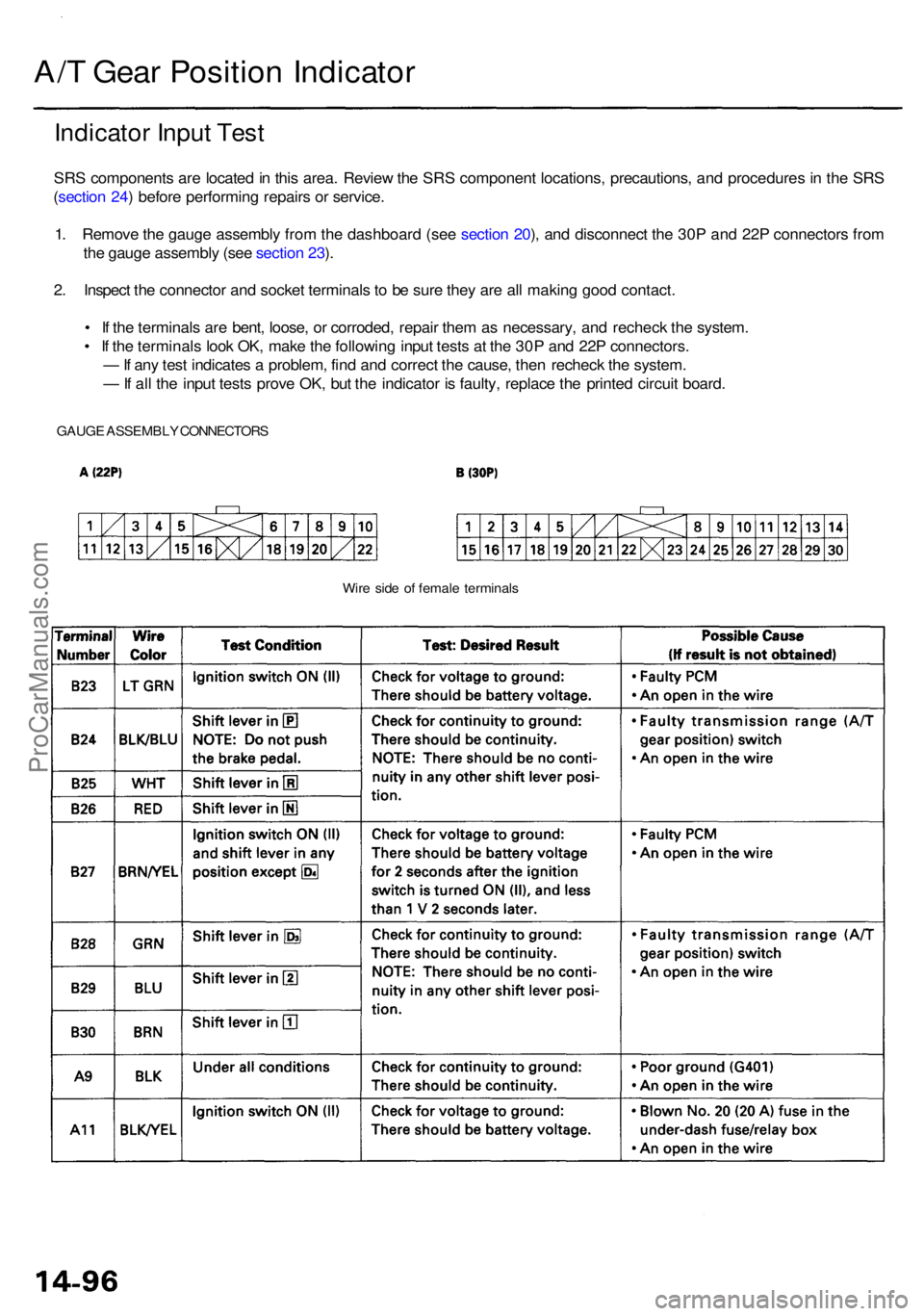
A/T Gea r Positio n Indicato r
Indicator Inpu t Tes t
SRS component s ar e locate d in thi s area . Revie w th e SR S componen t locations , precautions , an d procedure s i n th e SR S
( sectio n 24 ) befor e performin g repair s o r service .
1 . Remov e th e gaug e assembl y fro m th e dashboar d (se e sectio n 20 ), an d disconnec t th e 30 P an d 22 P connector s fro m
th e gaug e assembl y (se e sectio n 23 ).
2 . Inspec t th e connecto r an d socke t terminal s to b e sur e the y ar e al l makin g goo d contact .
• I f th e terminal s ar e bent , loose , o r corroded , repai r the m a s necessary , an d rechec k th e system .
• I f th e terminal s loo k OK , mak e th e followin g inpu t test s a t th e 30 P an d 22 P connectors .
— If an y tes t indicate s a problem , fin d an d correc t th e cause , the n rechec k th e system .
— If al l th e inpu t test s prov e OK , bu t th e indicato r i s faulty , replac e th e printe d circui t board .
GAUG E ASSEMBL Y CONNECTOR S
Wire sid e o f femal e terminal s
ProCarManuals.com
Page 877 of 1954
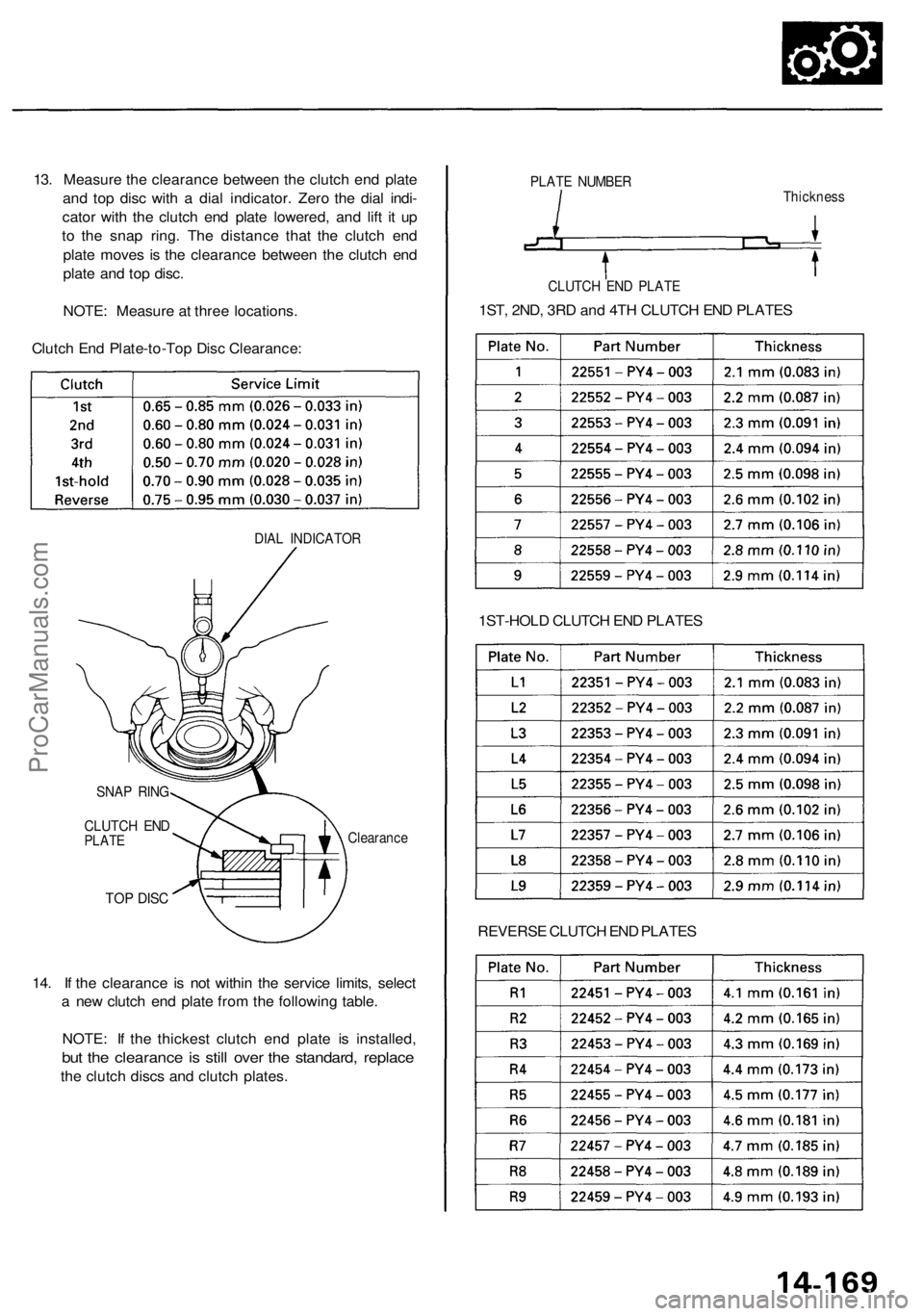
13. Measure the clearance between the clutch end plate
and top disc with a dial indicator. Zero the dial indi-
cator with the clutch end plate lowered, and lift it up
to the snap ring. The distance that the clutch end
plate moves is the clearance between the clutch end
plate and top disc.
NOTE: Measure at three locations.
Clutch End Plate-to-Top Disc Clearance:
DIAL INDICATOR
TOP DISC
14. If the clearance is not within the service limits, select
a new clutch end plate from the following table.
NOTE: If the thickest clutch end plate is installed,
but the clearance is still over the standard, replace
the clutch discs and clutch plates.
PLATE NUMBER
1ST-HOLD CLUTCH END PLATES
REVERSE CLUTCH END PLATES
CLUTCH END PLATE
1ST, 2ND, 3RD and 4TH CLUTCH END PLATES
Thickness
SNAP RING
CLUTCH END
PLATE
ClearanceProCarManuals.com
Page 1081 of 1954
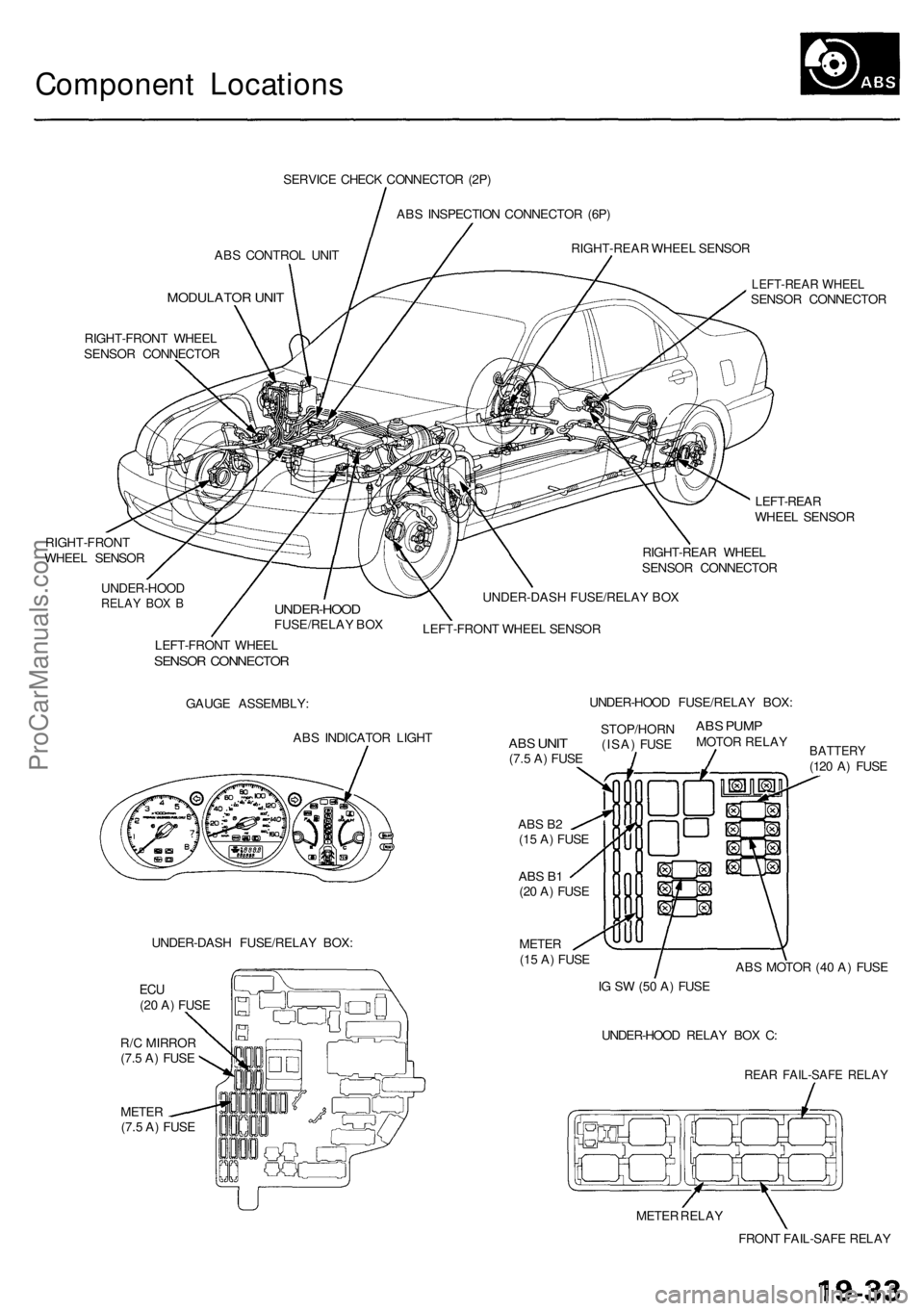
Component Locations
ABS CONTROL UNIT
MODULATOR UNIT
SERVICE CHECK CONNECTOR (2P)
ABS INSPECTION CONNECTOR (6P)
RIGHT-REAR WHEEL SENSOR
RIGHT-FRONT WHEEL
SENSOR CONNECTOR
RIGHT-FRONT
WHEEL SENSOR
LEFT-REAR WHEEL
SENSOR CONNECTOR
LEFT-REAR
WHEEL SENSOR
RIGHT-REAR WHEEL
SENSOR CONNECTOR
UNDER-HOOD
RELAY BOX B
UNDER-HOOD
FUSE/RELAY BOX
UNDER-DASH FUSE/RELAY BOX
LEFT-FRONT WHEEL SENSOR
LEFT-FRONT WHEEL
SENSOR CONNECTOR
GAUGE ASSEMBLY:
ABS INDICATOR LIGHT
UNDER-DASH FUSE/RELAY BOX:
METER
(7.5 A) FUSE
ABS B2
(15 A) FUSE
ABS B1
(20 A) FUSE
METER
(15 A) FUSE
BATTERY
(120 A) FUSE
ABS MOTOR (40 A) FUSE
IG SW (50 A) FUSE
UNDER-HOOD RELAY BOX C:
REAR FAIL-SAFE RELAY
METER RELAY
FRONT FAIL-SAFE RELAY
ABS
UNIT
(7.5 A) FUSE
STOP/HORN
(ISA) FUSE
ABS PUMP
MOTOR RELAY
UNDER-HOOD FUSE/RELAY BOX:
ECU
(20 A) FUSE
R/C MIRROR
(7.5 A) FUSEProCarManuals.com
Page 1087 of 1954
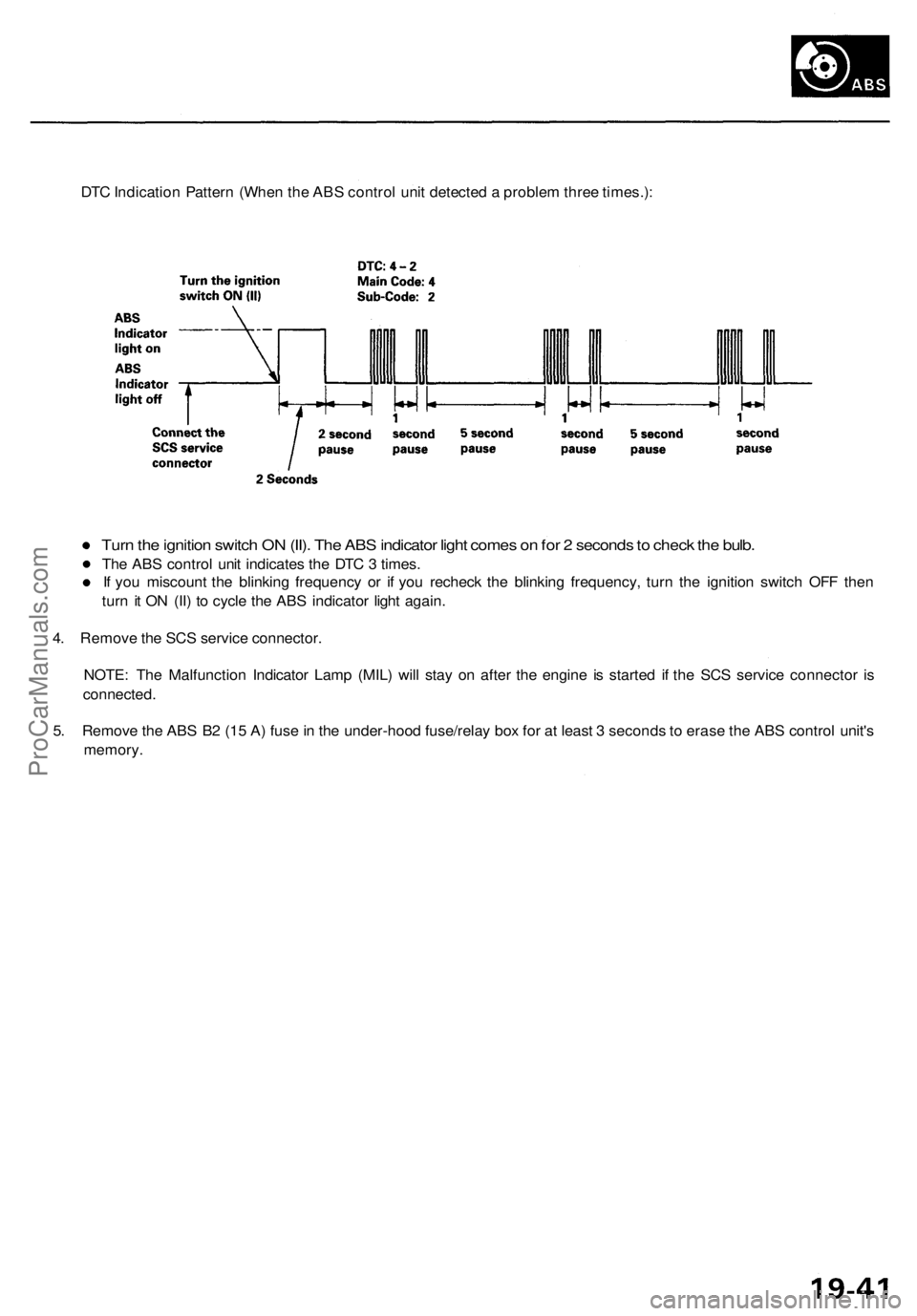
DTC Indication Pattern (When the ABS control unit detected a problem three times.):
Turn the ignition switch ON (II). The ABS indicator light comes on for 2 seconds to check the bulb.
The ABS control unit indicates the DTC 3 times.
If you miscount the blinking frequency or if you recheck the blinking frequency, turn the ignition switch OFF then
turn it ON (II) to cycle the ABS indicator light again.
4. Remove the SCS service connector.
NOTE: The Malfunction Indicator Lamp (MIL) will stay on after the engine is started if the SCS service connector is
connected.
5. Remove the ABS B2 (15 A) fuse in the under-hood fuse/relay box for at least 3 seconds to erase the ABS control unit's
memory.ProCarManuals.com