window ACURA RL KA9 1996 Service Repair Manual
[x] Cancel search | Manufacturer: ACURA, Model Year: 1996, Model line: RL KA9, Model: ACURA RL KA9 1996Pages: 1954, PDF Size: 61.44 MB
Page 34 of 1954
Power Windows
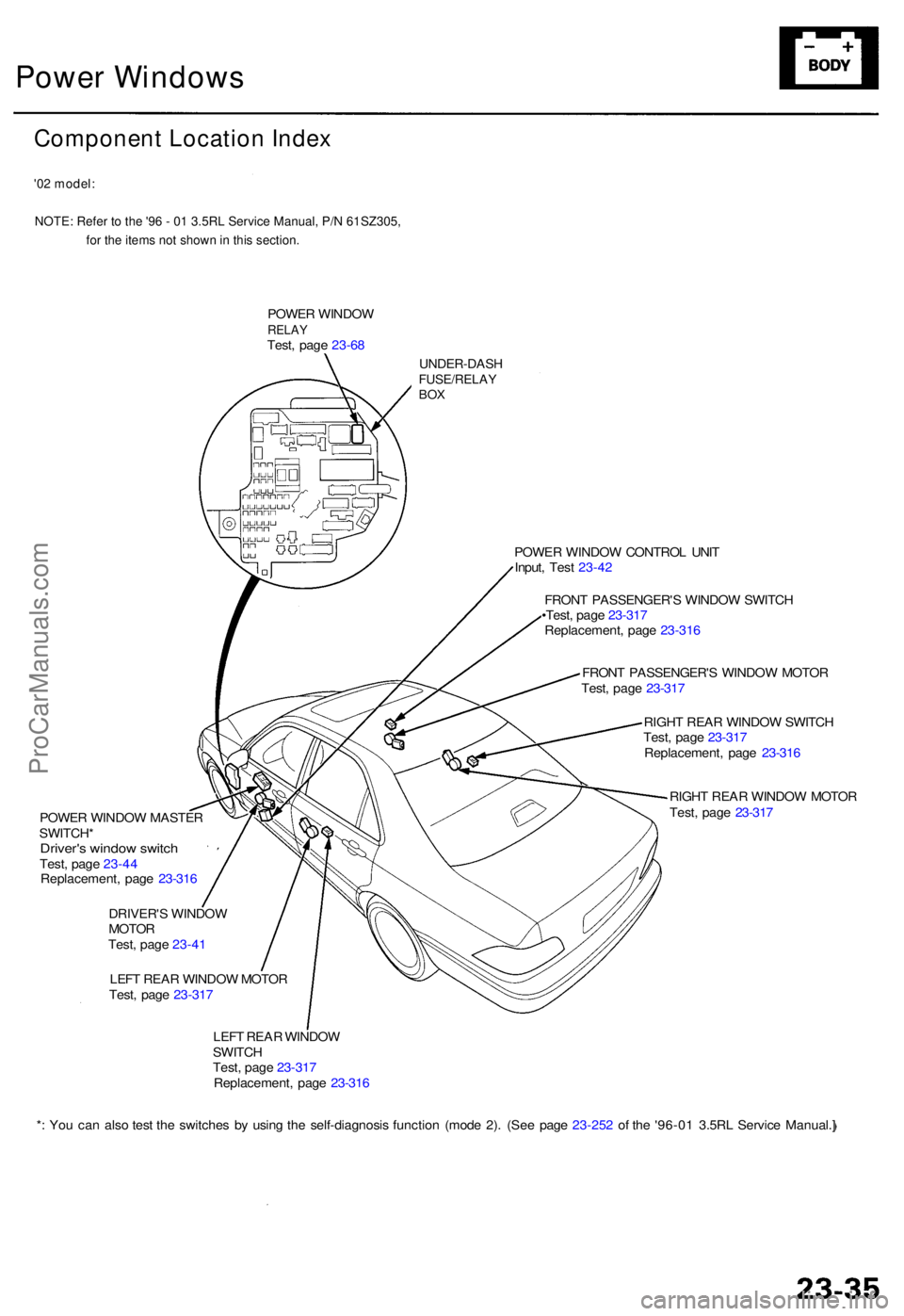
Component Location Index
'02 model:NOTE: Refer to the '96 - 01 3.5RL Service Manual, P/N 61SZ305, for the items not shown in this section.
POWER WINDO WRELAYTest, pag e 23-6 8
UNDER-DAS HFUSE/RELAYBOX
POWE R WINDO W MASTE R
SWITCH *
Driver's windo w switc hTest, pag e 23-4 4
Replacement , pag e 23-31 6
DRIVER' S WINDO W
MOTO R
Test , pag e 23-4 1
LEF T REA R WINDO W MOTO R
Test , pag e 23-31 7 POWE
R WINDO W CONTRO L UNI T
Input , Tes t 23-4 2
FRON T PASSENGER' S WINDO W SWITC H
•Test , pag e 23-31 7
Replacement , pag e 23-31 6
FRON T PASSENGER' S WINDO W MOTO R
Test , pag e 23-31 7
RIGH T REA R WINDO W SWITC H
Test , pag e 23-31 7
Replacement , pag e 23-31 6
RIGH T REA R WINDO W MOTO R
Test , pag e 23-31 7
LEF T REA R WINDO W
SWITC H
Test , pag e 23-31 7
Replacement , pag e 23-31 6
* : Yo u ca n als o tes t th e switche s b y usin g th e self-diagnosi s functio n (mod e 2) . (Se e pag e 23-25 2 o f th e '96-0 1 3.5R L Servic e Manual. ]
ProCarManuals.com
Page 35 of 1954
Power Window s
Description s
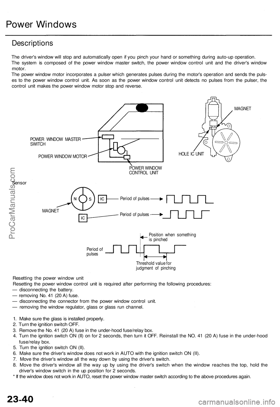
The driver' s windo w wil l sto p an d automaticall y ope n i f yo u pinc h you r han d o r somethin g durin g auto-u p operation .
Th e syste m is compose d o f th e powe r windo w maste r switch , th e powe r windo w contro l uni t an d th e driver' s windo w
motor.
The powe r windo w moto r incorporate s a pulse r whic h generate s pulse s durin g th e motor' s operatio n an d send s th e puls -
e s t o th e powe r windo w contro l unit . As soo n a s th e powe r windo w contro l uni t detect s n o pulse s fro m th e pulser , th e
contro l uni t make s th e powe r windo w moto r sto p an d reverse .
POWER WINDO W MASTE R
SWITC H
POWE R WINDO W MOTO R HOL
E IC UNI T MAGNE
T
POWE R WINDO W
CONTRO L UNI T
Senso r
MAGNE T
Period o f pulse s -
Perio d o f
pulse s Positio
n whe n somethin g
i s pinche d
Threshol d valu e fo r
judgmen t o f pinchin g
Resettin g th e powe r windo w uni t
Resettin g th e powe r windo w contro l uni t i s require d afte r performin g th e followin g procedures :
— disconnectin g th e battery .
— removin g No . 4 1 (2 0 A ) fuse .
— disconnectin g th e connecto r fro m th e powe r windo w contro l unit .
— removin g th e windo w regulator , glas s o r glas s ru n channel .
1. Mak e sur e th e glas s is installe d properly .
2. Tur n th e ignitio n switc h OFF .
3. Remov e th e No . 4 1 (2 0 A ) fus e in th e under-hoo d fuse/rela y box .
4 . Tur n th e ignitio n switc h O N (II ) o n fo r 2 seconds , the n tur n it OFF . Reinstal l th e NO . 4 1 (2 0 A ) fus e in th e under-hoo d
fuse/rela y box .
5 . Tur n th e ignitio n switc h O N (II) .
6 . Mak e sur e th e driver' s windo w doe s no t wor k in AUT O wit h th e ignitio n switc h O N (II) .
7 . Mov e th e driver' s windo w al l th e wa y dow n b y usin g th e driver' s switch .
8 . Mov e th e driver' s windo w al l th e wa y u p b y usin g th e driver' s switc h whe n th e windo w reache s th e top , hol d th e
driver' s windo w switc h in th e u p positio n fo r 2 seconds .
* I f th e windo w doe s no t wor k in AUTO , rese t th e powe r windo w maste r switc h accordin g to th e abov e procedure s again .
Period o f pulse s
ProCarManuals.com
Page 37 of 1954
Power Window s
Control Uni t Inpu t Tes t
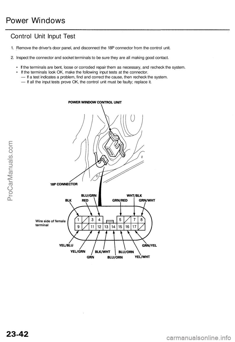
1. Remov e th e driver' s doo r panel , an d disconnec t th e 18 P connecto r fro m th e contro l unit .
2 . Inspec t th e connecto r an d socke t terminal s t o b e sur e the y ar e al l makin g goo d contact .
• I f th e terminal s ar e bent , loos e o r corrode d repai r the m a s necessary , an d rechec k th e system .
• I f th e terminal s loo k OK , mak e th e followin g inpu t test s a t th e connector .
— If a tes t indicate s a problem , fin d an d correc t th e cause , the n rechec k th e system .
— If al l th e inpu t test s prov e OK , th e contro l uni t mus t b e faulty ; replac e it .
ProCarManuals.com
Page 39 of 1954
Power Windows
Driver's Window Switch Test
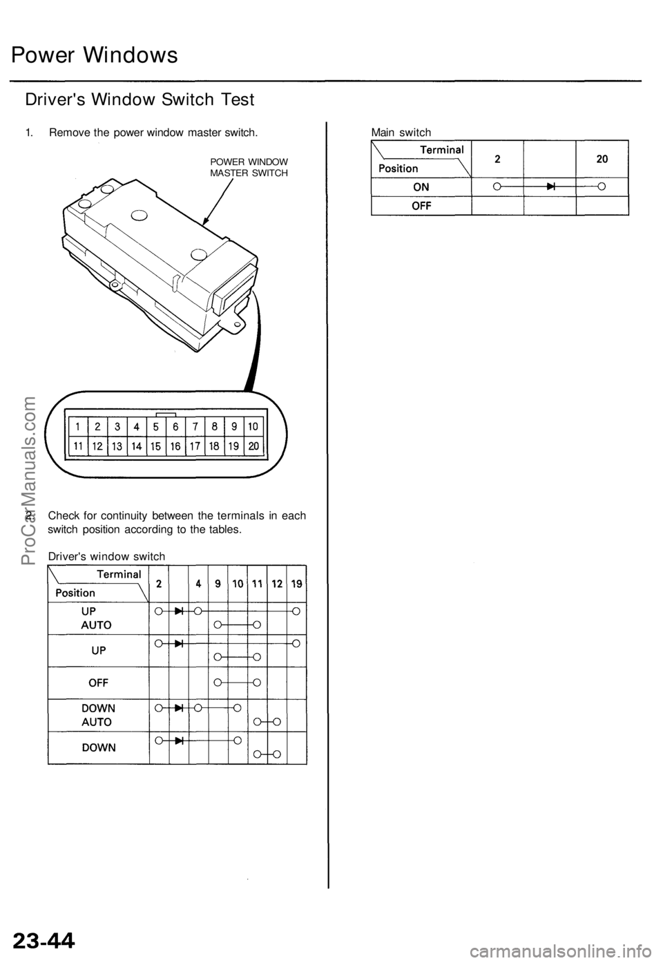
1. Remove the power window master switch.
POWER WINDOW
MASTER SWITCH
2. Check for continuity between the terminals in each
switch position according to the tables.
Driver's window switch
Main switchProCarManuals.com
Page 247 of 1954
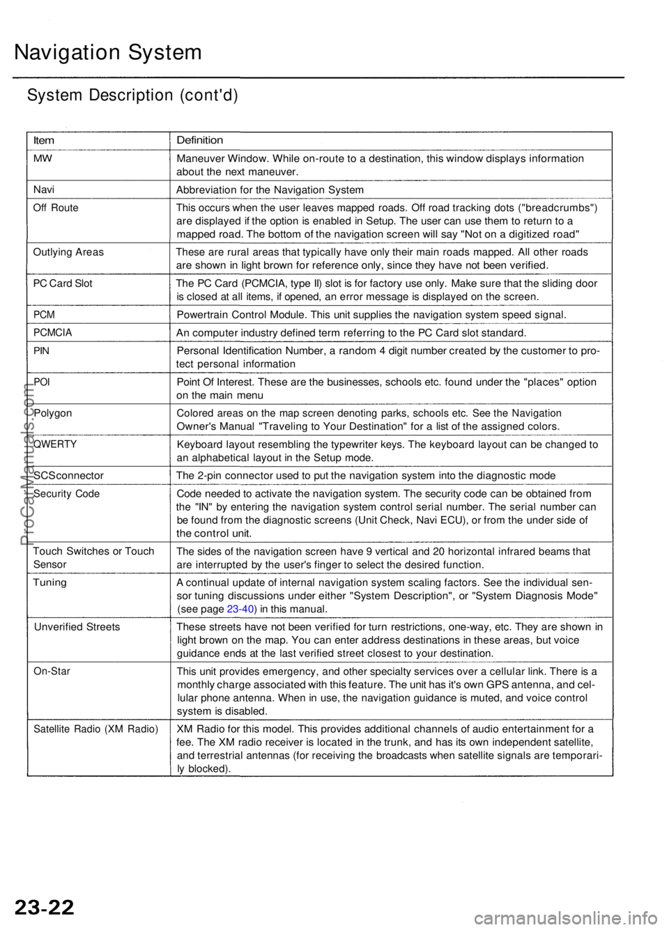
Navigation Syste m
System Descriptio n (cont'd )
Item
MW
Nav i
Off Rout e
Outlyin g Area s
PC Car d Slo t
PCM
PCMCI A
PIN
PO I
Polygo n
QWERT Y
SCS connecto r
Security Cod e
Touc h Switche s o r Touc h
Senso r
Tuning
Unverifie d Street s
On-Sta r
Satellite Radi o (X M Radio )
Definitio n
Maneuve r Window . Whil e on-rout e to a destination , thi s windo w display s informatio n
about th e nex t maneuver .
Abbreviatio n fo r th e Navigatio n Syste m
This occur s whe n th e use r leave s mappe d roads . Of f roa d trackin g dot s ("breadcrumbs" )
are displaye d if th e optio n is enable d in Setup . Th e use r ca n us e the m to retur n t o a
mappe d road . Th e botto m o f th e navigatio n scree n wil l sa y "No t o n a digitize d road "
These ar e rura l area s tha t typicall y hav e onl y their main road s mapped . Al l othe r road s
are show n in ligh t brow n fo r referenc e only , sinc e the y hav e no t bee n verified .
The P C Car d (PCMCIA , typ e II ) slo t i s fo r factor y us e only . Mak e sur e tha t th e slidin g doo r
is close d a t al l items , i f opened , a n erro r messag e is displaye d o n th e screen .
Powertrai n Contro l Module . Thi s uni t supplie s th e navigatio n syste m spee d signal .
An compute r industr y define d ter m referrin g t o th e P C Car d slo t standard .
Personal Identificatio n Number , a rando m 4 digi t numbe r create d b y th e custome r t o pro -
tect persona l informatio n
Point O f Interest . Thes e ar e th e businesses , school s etc . foun d unde r th e "places " optio n
on th e mai n men u
Colore d area s o n th e ma p scree n denotin g parks , school s etc . Se e th e Navigatio n
Owner's Manua l "Travelin g t o You r Destination " fo r a lis t o f th e assigne d colors .
Keyboar d layou t resemblin g th e typewrite r keys . Th e keyboar d layou t ca n b e change d t o
a n alphabetica l layou t i n th e Setu p mode .
The 2-pi n connecto r use d t o pu t th e navigatio n syste m int o th e diagnosti c mod e
Code neede d to activat e th e navigatio n system . Th e securit y cod e ca n b e obtaine d fro m
the "IN " b y enterin g th e navigatio n syste m contro l seria l number . Th e seria l numbe r ca n
be foun d fro m th e diagnosti c screen s (Uni t Check , Nav i ECU) , o r fro m th e unde r sid e o f
the contro l unit .
The side s o f th e navigatio n scree n hav e 9 vertica l an d 2 0 horizonta l infrare d beam s tha t
are interrupte d b y th e user' s finge r t o selec t th e desire d function .
A continua l updat e o f interna l navigatio n syste m scalin g factors . Se e th e individua l sen -
sor tunin g discussion s unde r eithe r "Syste m Description" , o r "Syste m Diagnosi s Mode "
(see pag e 23-40 ) i n thi s manual .
These street s hav e no t bee n verifie d fo r tur n restrictions , one-way , etc . The y ar e show n i n
ligh t brow n o n th e map . Yo u ca n ente r addres s destination s i n thes e areas , bu t voic e
guidanc e end s a t th e las t verifie d stree t closes t t o you r destination .
This uni t provide s emergency , an d othe r specialt y service s ove r a cellula r link . Ther e is a
monthl y charg e associate d wit h thi s feature . Th e uni t ha s it' s ow n GP S antenna , an d cel -
lula r phon e antenna . Whe n in use , th e navigatio n guidanc e is muted , an d voic e contro l
system is disabled .
XM Radi o fo r thi s model . Thi s provide s additiona l channel s o f audi o entertainmen t fo r a
fee . Th e X M radi o receive r i s locate d in th e trunk , an d ha s it s ow n independen t satellite ,
and terrestria l antenna s (fo r receivin g th e broadcast s whe n satellit e signal s ar e temporari -
ly blocked) .
ProCarManuals.com
Page 260 of 1954
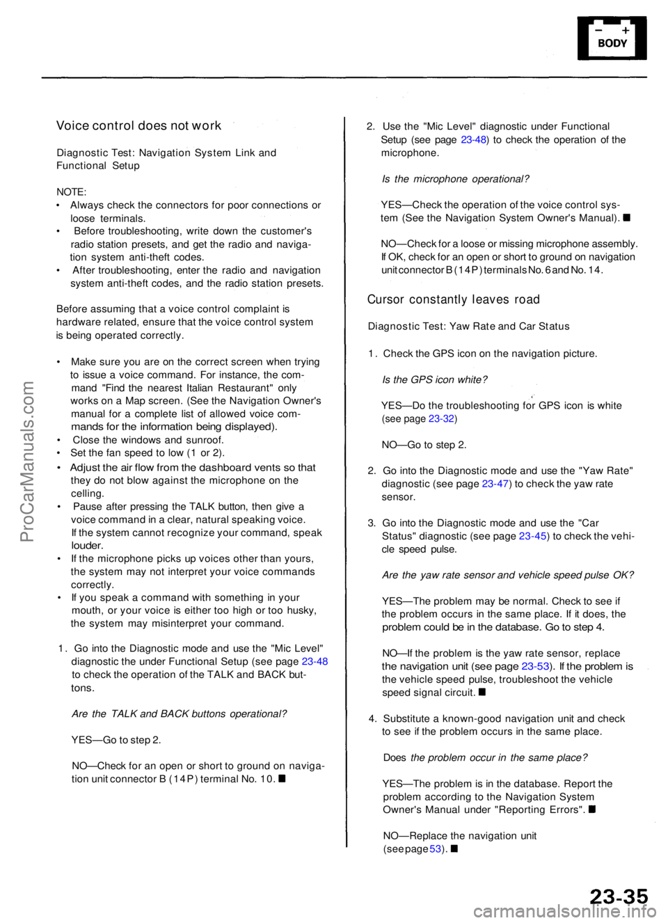
Voice contro l doe s no t wor k
Diagnosti c Test : Navigatio n Syste m Lin k an d
Functiona l Setu p
NOTE :
• Alway s chec k th e connector s fo r poo r connection s o r
loos e terminals .
• Befor e troubleshooting , writ e dow n th e customer' s
radi o statio n presets , an d ge t th e radi o an d naviga -
tio n syste m anti-thef t codes .
• Afte r troubleshooting , ente r th e radi o an d navigatio n
syste m anti-thef t codes , an d th e radi o statio n presets .
Befor e assumin g tha t a voic e contro l complain t i s
hardwar e related , ensur e tha t th e voic e contro l syste m
i s bein g operate d correctly .
• Mak e sur e yo u ar e o n th e correc t scree n whe n tryin g
t o issu e a voic e command . Fo r instance , th e com -
man d "Fin d th e neares t Italia n Restaurant " onl y
work s o n a Ma p screen . (Se e th e Navigatio n Owner' s
manua l fo r a complet e lis t o f allowe d voic e com -
mand s fo r th e informatio n bein g displayed) .
• Clos e th e window s an d sunroof .
• Se t th e fa n spee d t o lo w (1 o r 2) .
• Adjus t th e ai r flo w fro m th e dashboar d vent s s o tha t
they d o no t blo w agains t th e microphon e o n th e
celling .
• Paus e afte r pressin g th e TAL K button , the n giv e a
voic e comman d in a clear , natura l speakin g voice .
I f th e syste m canno t recogniz e you r command , spea k
louder .
• I f th e microphon e pick s u p voice s othe r tha n yours ,
th e syste m ma y no t interpre t you r voic e command s
correctly .
• I f yo u spea k a comman d wit h somethin g in you r
mouth , o r you r voic e is eithe r to o hig h o r to o husky ,
th e syste m ma y misinterpre t you r command .
1 . G o int o th e Diagnosti c mod e an d us e th e "Mi c Level "
diagnosti c th e unde r Functiona l Setu p (se e pag e 23 -48
t o chec k th e operatio n o f th e TAL K an d BAC K but -
tons.
Are the TALK and BACK buttons operational?
YES—G o to ste p 2 .
NO—Chec k fo r a n ope n o r shor t t o groun d o n naviga -
tio n uni t connecto r B (14P ) termina l No . 10 . 2
. Us e th e "Mi c Level " diagnosti c unde r Functiona l
Setu p (se e pag e 23-48 ) t o chec k th e operatio n o f th e
microphone .
Is the microphone operational?
YES—Chec k th e operatio n o f th e voic e contro l sys -
te m (Se e th e Navigatio n Syste m Owner' s Manual) .
NO—Chec k fo r a loos e o r missin g microphon e assembly .
I f OK , chec k fo r a n ope n o r shor t t o groun d o n navigatio n
uni t connecto r B (14P ) terminal s No . 6 an d No . 14 .
Curso r constantl y leave s roa d
Diagnosti c Test : Ya w Rat e an d Ca r Statu s
1 . Chec k th e GP S ico n o n th e navigatio n picture .
Is the GPS icon white?
YES—D o th e troubleshootin g fo r GP S ico n i s whit e
(see page 23-32)
NO—G o t o ste p 2 .
2 . G o int o th e Diagnosti c mod e an d us e th e "Ya w Rate "
diagnosti c (se e pag e 23-47 ) t o chec k th e ya w rat e
sensor .
3. G o int o th e Diagnosti c mod e an d us e th e "Ca r
Status " diagnosti c (se e pag e 23-45 ) t o chec k th e vehi -
cl e spee d pulse .
Are the yaw rate sensor and vehicle speed pulse OK?
YES—Th e proble m ma y b e normal . Chec k t o se e if
th e proble m occur s i n th e sam e place . I f i t does , th e
proble m coul d b e in th e database . G o to ste p 4 .
NO—I f th e proble m is th e ya w rat e sensor , replac e
the navigatio n uni t (se e pag e 23-53 ). I f th e proble m is
th e vehicl e spee d pulse , troubleshoo t th e vehicl e
spee d signa l circuit .
4 . Substitut e a known-goo d navigatio n uni t an d chec k
t o se e if th e proble m occur s i n th e sam e place .
Doe s the problem occur in the same place?
YES—Th e proble m is in th e database . Repor t th e
proble m accordin g t o th e Navigatio n Syste m
Owner' s Manua l unde r "Reportin g Errors" .
NO—Replac e th e navigatio n uni t
(se e pag e 53 ).
ProCarManuals.com
Page 1320 of 1954
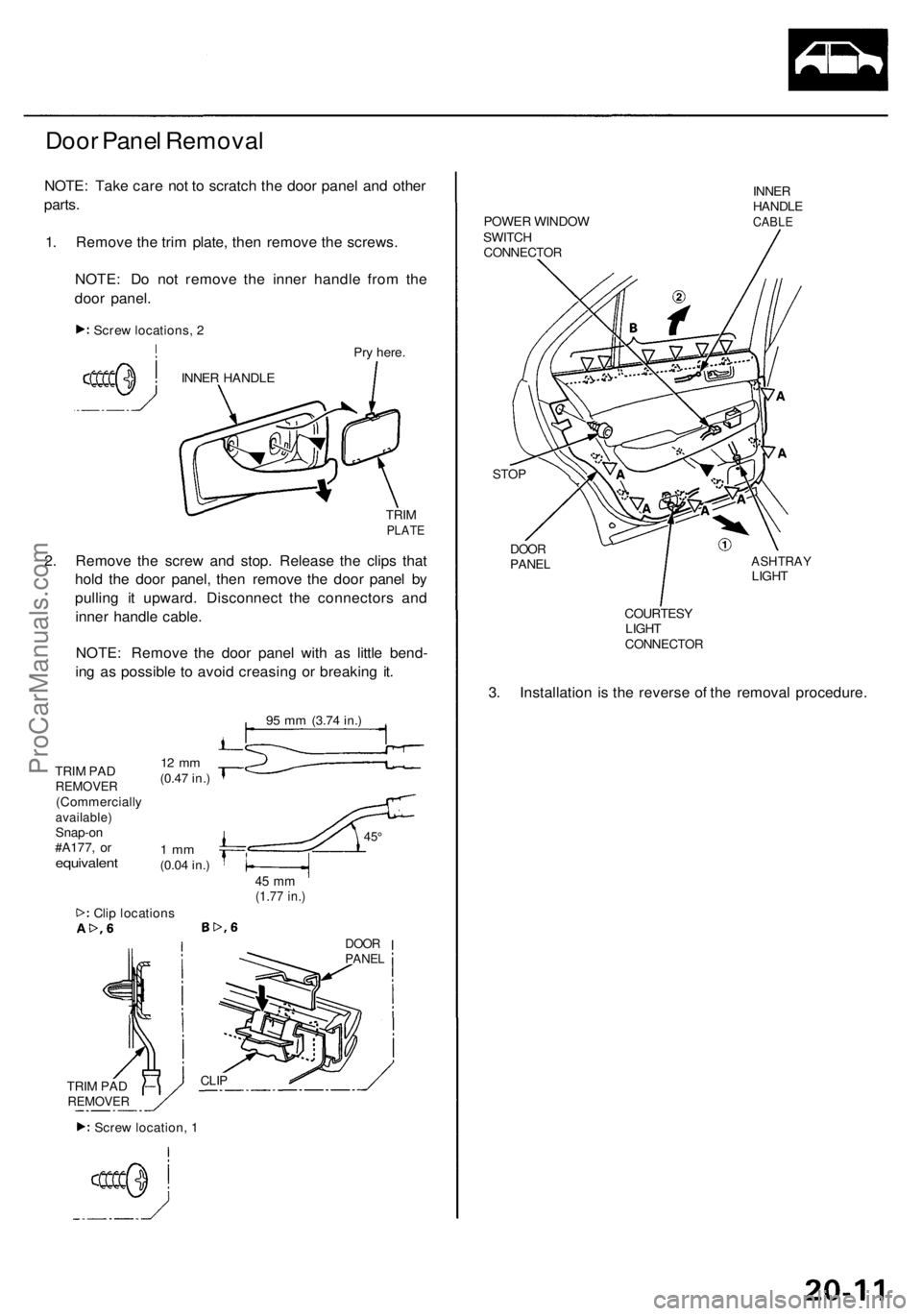
Door Panel Removal
NOTE: Take care not to scratch the door panel and other
parts.
1. Remove the trim plate, then remove the screws.
NOTE: Do not remove the inner handle from the
door panel.
Pry here.
TRIM
PLATE
2. Remove the screw and stop. Release the clips that
hold the door panel, then remove the door panel by
pulling it upward. Disconnect the connectors and
inner handle cable.
NOTE: Remove the door panel with as little bend-
ing as possible to avoid creasing or breaking it.
95 mm
(3.74 in.)
TRIM PAD
REMOVER
(Commercially
available)
Snap-on
#A177, or
equivalent
12 mm
(0.47 in.)
1 mm
(0.04 in.)
45°
45 mm
(1.77 in.)
Clip locations
DOOR
PANEL
CLIP
POWER WINDOW
SWITCH
CONNECTOR
INNER
HANDLE
CABLE
STOP
DOOR
PANEL
ASHTRAY
LIGHT
COURTESY
LIGHT
CONNECTOR
3. Installation is the reverse of the removal procedure.
1
Screw locations, 2
INNER HANDLE
TRIM PAD
REMOVER
Screw location, 1ProCarManuals.com
Page 1333 of 1954
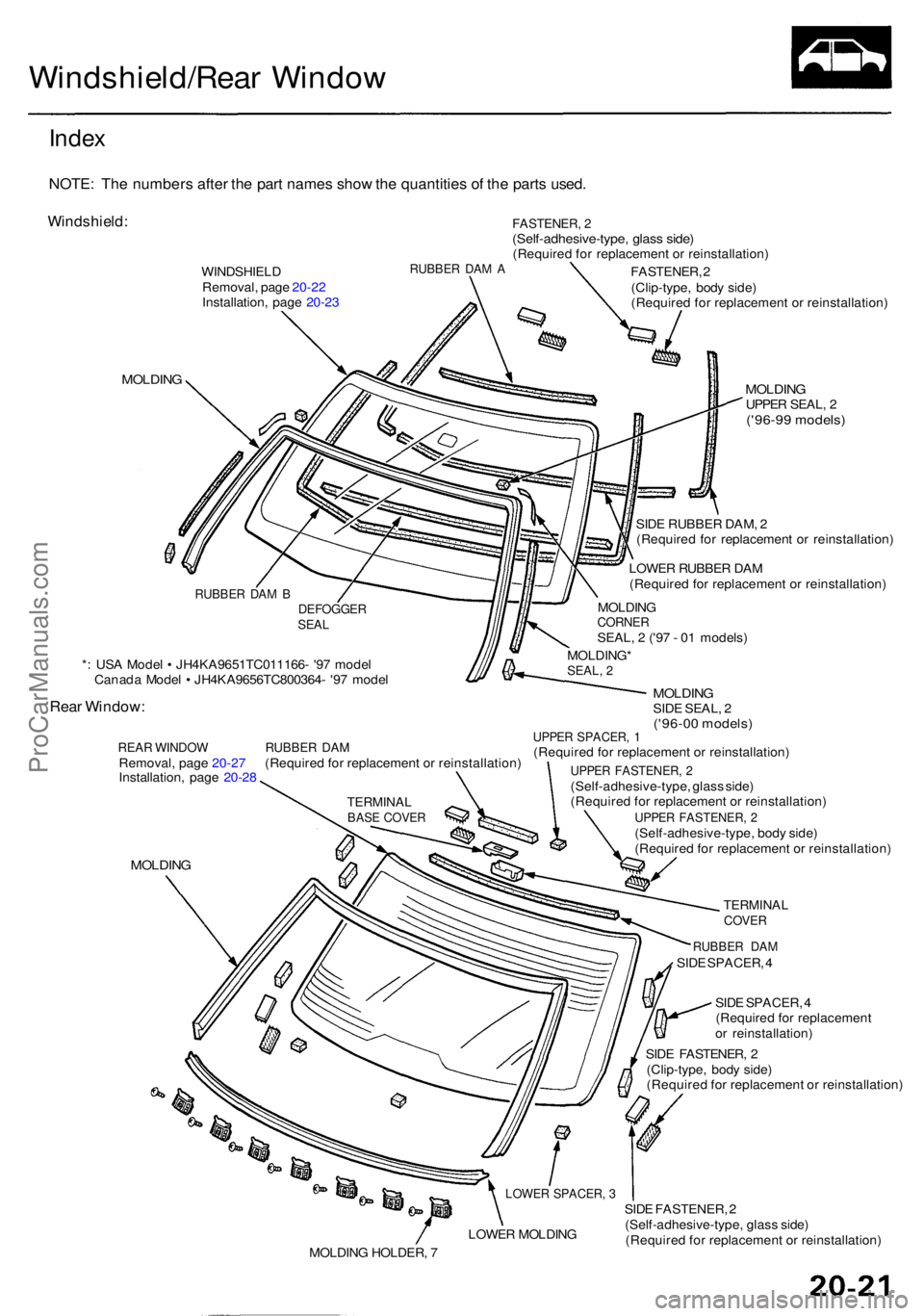
Windshield/Rear Windo w
Index
NOTE : Th e number s afte r th e par t name s sho w th e quantitie s o f th e part s used .
Windshield :
WINDSHIEL D
Removal , pag e 20-2 2
Installation , pag e 20-2 3RUBBE R DA M A
FASTENER , 2(Self-adhesive-type , glas s side )(Require d fo r replacemen t o r reinstallation )
MOLDING
*: US A Mode l • JH4KA9651TC011166 - '9 7 mode l
Canad a Mode l • JH4KA9656TC800364 - '9 7 mode l
Rear Window :
REAR WINDO W RUBBE R DA MRemoval , pag e 20-2 7 (Require d fo r replacemen t o r reinstallation )
Installation , pag e 20-2 8
MOLDIN G
FASTENER , 2
(Clip-type , bod y side )
(Require d fo r replacemen t o r reinstallation )
MOLDINGUPPER SEAL , 2('96-9 9 models )
RUBBER DA MSIDE SPACER , 4
SID E SPACER , 4
(Require d fo r replacemen t
o r reinstallation )
SID E FASTENER , 2
(Clip-type , bod y side )
(Require d fo r replacemen t o r reinstallation )
SID E FASTENER , 2
(Self-adhesive-type , glas s side )
(Require d fo r replacemen t o r reinstallation )
DEFOGGERSEAL
MOLDING *SEAL, 2
MOLDIN GCORNERSEAL, 2 ('9 7 - 0 1 models )
LOWE
R RUBBE R DA M
(Require d fo r replacemen t o r reinstallation )
SID
E RUBBE R DAM , 2
(Require d fo r replacemen t o r reinstallation )
MOLDINGSIDE SEAL , 2('96-0 0 models )UPPER SPACER , 1(Require d fo r replacemen t o r reinstallation )
UPPER FASTENER , 2(Self-adhesive-type , glas s side )
(Require d fo r replacemen t o r reinstallation )
UPPER FASTENER , 2(Self-adhesive-type , bod y side )
(Require d fo r replacemen t o r reinstallation )
TERMINALCOVER
LOWE R SPACER , 3
LOWE R MOLDIN G
MOLDIN G HOLDER , 7
TERMINA LBASE COVE R
RUBBE R DA M B
ProCarManuals.com
Page 1338 of 1954
Windshield
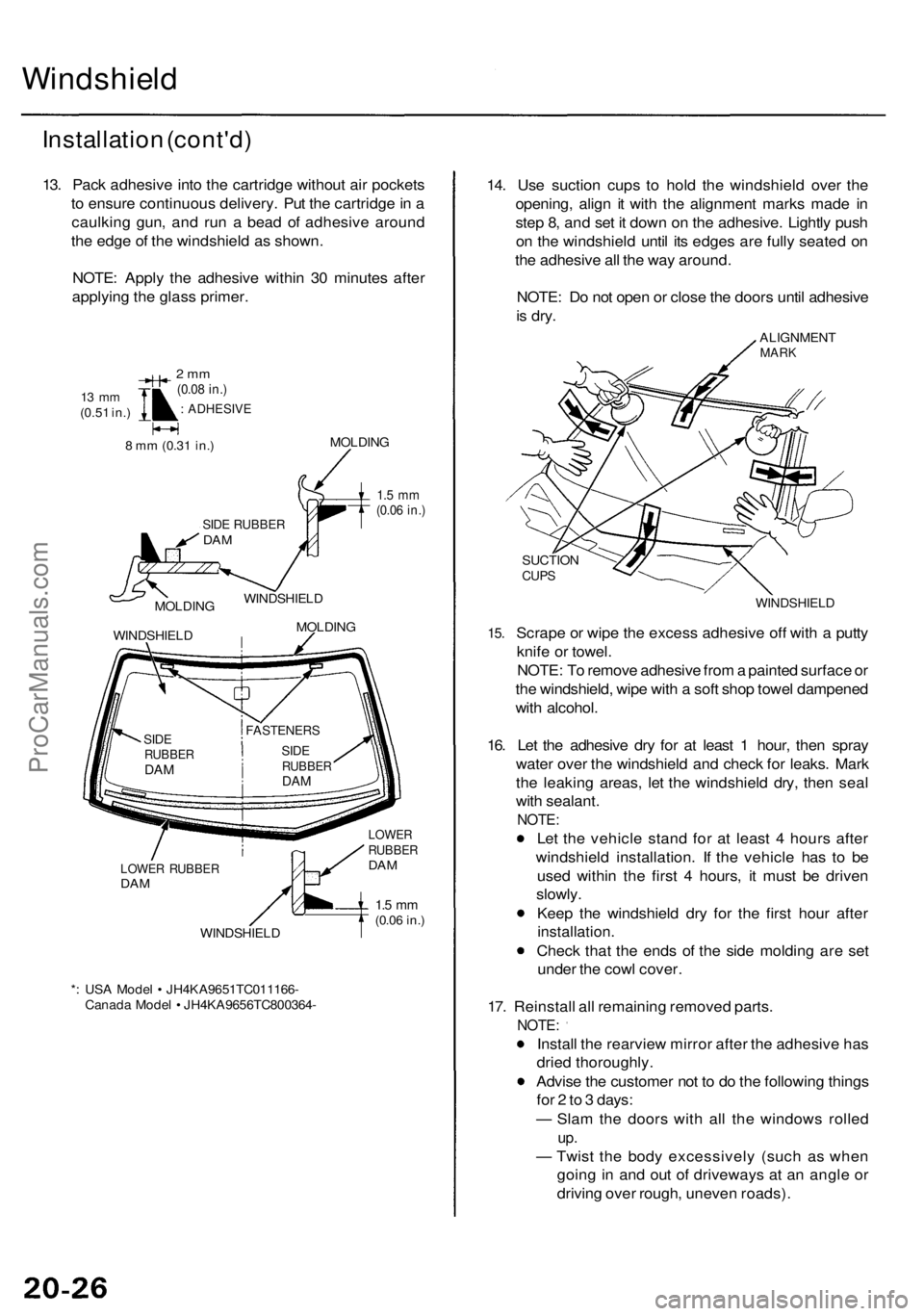
Installation (cont'd )
13. Pac k adhesiv e int o th e cartridg e withou t ai r pocket s
t o ensur e continuou s delivery . Pu t th e cartridg e in a
caulkin g gun , an d ru n a bea d o f adhesiv e aroun d
th e edg e o f th e windshiel d a s shown .
NOTE : Appl y th e adhesiv e withi n 3 0 minute s afte r
applyin g th e glas s primer .
13 m m(0.5 1 in. )
2 m m(0.0 8 in. )
: ADHESIV E
8 m m (0.3 1 in. )MOLDIN G
SIDE RUBBE RDAM
1.5 m m(0.0 6 in. )
MOLDIN G
WINDSHIEL DWINDSHIEL
D
MOLDIN G
LOWER RUBBE RDAM
WINDSHIEL D
* : US A Mode l • JH4KA9651TC011166 -
Canad a Mode l • JH4KA9656TC800364 -
LOWERRUBBE RDAM
1.5 m m(0.0 6 in. )
14. Us e suctio n cup s t o hol d th e windshiel d ove r th e
opening , alig n i t wit h th e alignmen t mark s mad e i n
ste p 8 , an d se t i t dow n o n th e adhesive . Lightl y pus h
o n th e windshiel d unti l it s edge s ar e full y seate d o n
th e adhesiv e al l th e wa y around .
NOTE : D o no t ope n o r clos e th e door s unti l adhesiv e
is dry .
ALIGNMEN TMARK
15.
SUCTIO NCUPS
WINDSHIEL D
Scrape o r wip e th e exces s adhesiv e of f wit h a putt y
knif e o r towel .
NOTE : T o remov e adhesiv e fro m a painte d surfac e o r
th e windshield , wip e wit h a sof t sho p towe l dampene d
wit h alcohol .
16 . Le t th e adhesiv e dr y fo r a t leas t 1 hour , the n spra y
wate r ove r th e windshiel d an d chec k fo r leaks . Mar k
th e leakin g areas , le t th e windshiel d dry , the n sea l
wit h sealant .
NOTE:
Let th e vehicl e stan d fo r a t leas t 4 hour s afte r
windshiel d installation . I f th e vehicl e ha s t o b e
use d withi n th e firs t 4 hours , i t mus t b e drive n
slowly .
Kee p th e windshiel d dr y fo r th e firs t hou r afte r
installation .
Check tha t th e end s o f th e sid e moldin g ar e se t
unde r th e cow l cover .
17 . Reinstal l al l remainin g remove d parts .
NOTE :
Install th e rearvie w mirro r afte r th e adhesiv e ha s
drie d thoroughly .
Advis e th e custome r no t t o d o th e followin g thing s
fo r 2 to 3 days :
— Sla m th e door s wit h al l th e window s rolle d
up.
— Twis t th e bod y excessivel y (suc h a s whe n
goin g i n an d ou t o f driveway s a t a n angl e o r
drivin g ove r rough , uneve n roads) .
FASTENER S
SIDERUBBE RDAM
SID ERUBBE RDAM
ProCarManuals.com
Page 1339 of 1954
Rear Windo w
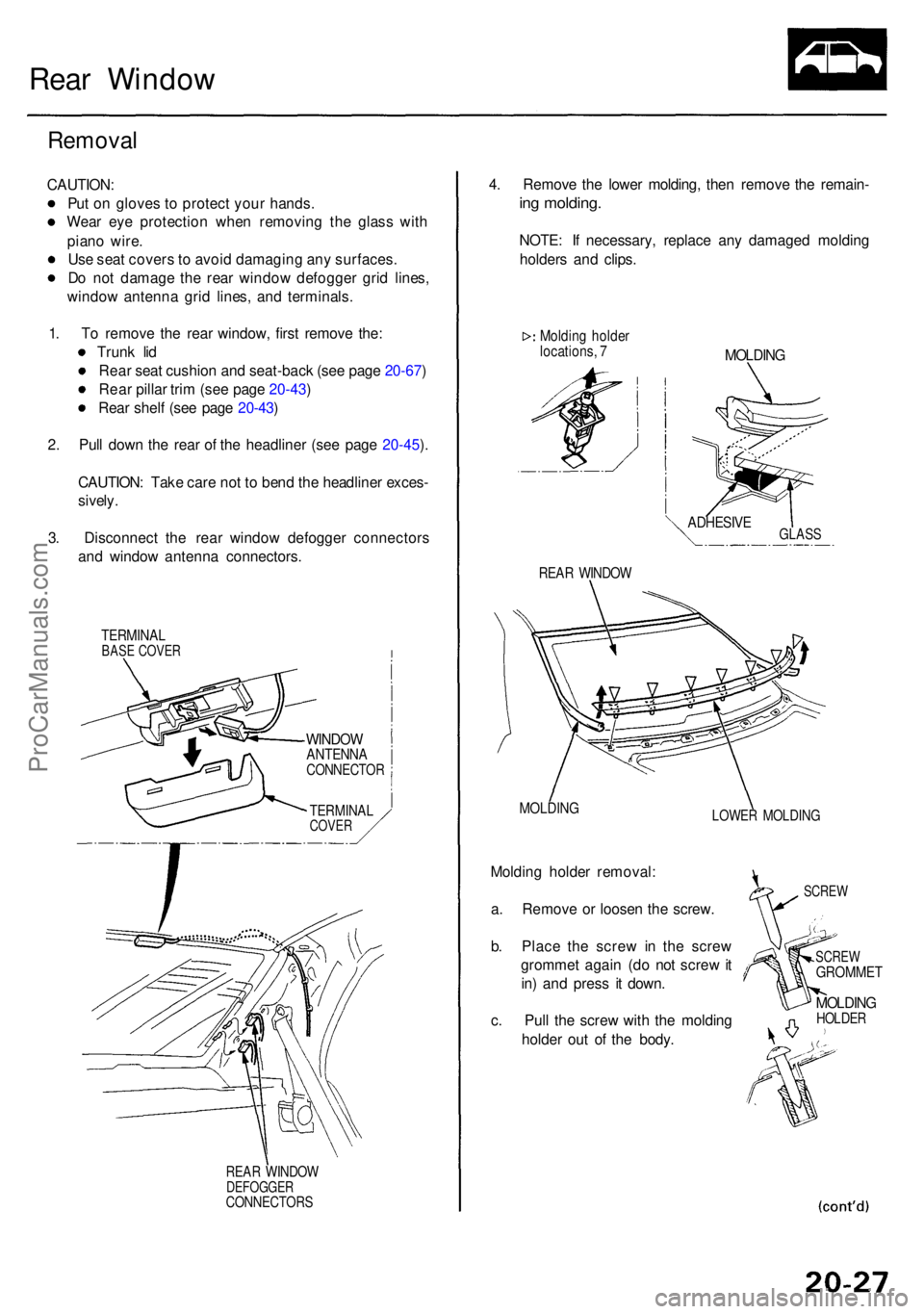
Remova l
CAUTION :
Pu t o n glove s t o protec t you r hands .
Wea r ey e protectio n whe n removin g th e glas s wit h
pian o wire .
Us e sea t cover s to avoi d damagin g an y surfaces .
D o no t damag e th e rea r windo w defogge r gri d lines ,
windo w antenn a gri d lines , an d terminals .
1 . T o remov e th e rea r window , firs t remov e the :
Trun k li d
Rea r sea t cushio n an d seat-bac k (se e pag e 20-67 )
Rea r pilla r tri m (se e pag e 20-43 )
Rea r shel f (se e pag e 20-43 )
2 . Pul l dow n th e rea r o f th e headline r (se e pag e 20-45 ).
CAUTION : Tak e car e no t t o ben d th e headline r exces -
sively.
3. Disconnec t th e rea r windo w defogge r connector s
an d windo w antenn a connectors .
TERMINALBASE COVE R
REAR WINDO WDEFOGGE RCONNECTOR S
4. Remov e th e lowe r molding , the n remov e th e remain -
ing molding .
NOTE: I f necessary , replac e an y damage d moldin g
holder s an d clips .
Moldin g holde rlocations , 7MOLDIN G
REAR WINDO W
MOLDIN GLOWER MOLDIN G
Molding holde r removal :
a . Remov e o r loose n th e screw .
b . Plac e th e scre w i n th e scre w
gromme t agai n (d o no t scre w it
in ) an d pres s i t down .
c . Pul l th e scre w wit h th e moldin g
holde r ou t o f th e body .
SCRE W
SCRE W
GROMME T
MOLDINGHOLDER
WINDOWANTENN ACONNECTO R
TERMINALCOVER
GLASSADHESIV E
ProCarManuals.com