ECU ACURA TL 1995 Service Repair Manual
[x] Cancel search | Manufacturer: ACURA, Model Year: 1995, Model line: TL, Model: ACURA TL 1995Pages: 1771, PDF Size: 62.49 MB
Page 75 of 1771
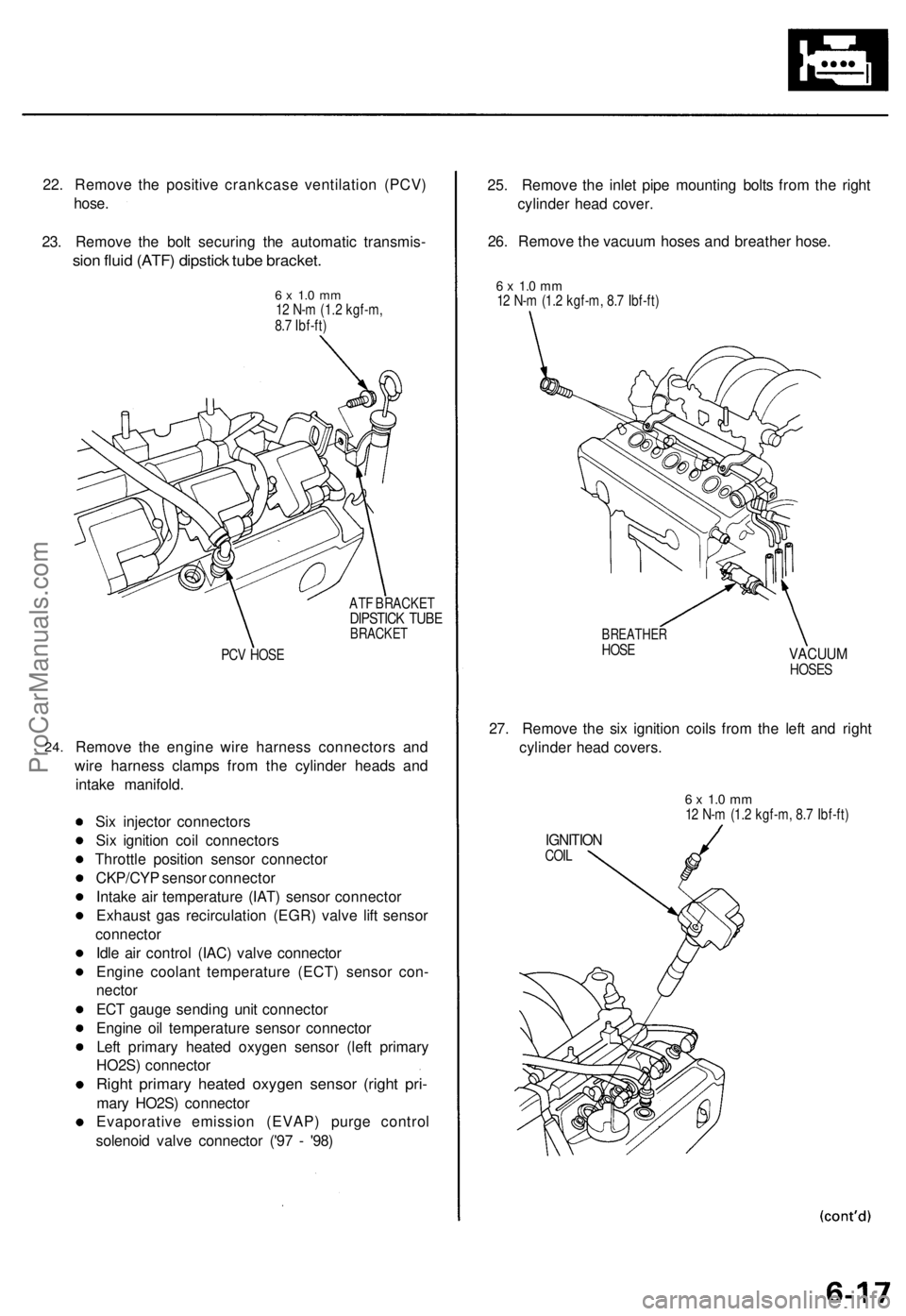
22. Remove the positive crankcase ventilation (PCV)
hose.
23. Remove the bolt securing the automatic transmis-
sion fluid (ATF) dipstick tube bracket.
6 x 1.0 mm
12 N-m (1.2 kgf-m,
8.7 Ibf-ft)
ATF BRACKET
DIPSTICK TUBE
BRACKET
PCV HOSE
24.
Remove the engine wire harness connectors and
wire harness clamps from the cylinder heads and
intake manifold.
Six injector connectors
Six ignition coil connectors
Throttle position sensor connector
CKP/CYP sensor connector
Intake air temperature (IAT) sensor connector
Exhaust gas recirculation (EGR) valve lift sensor
connector
Idle air control (IAC) valve connector
Engine coolant temperature (ECT) sensor con-
nector
ECT gauge sending unit connector
Engine oil temperature sensor connector
Left primary heated oxygen sensor (left primary
HO2S) connector
Right primary heated oxygen sensor (right pri-
mary HO2S) connector
Evaporative emission (EVAP) purge control
solenoid valve connector ('97 - '98)
25. Remove the inlet pipe mounting bolts from the right
cylinder head cover.
26. Remove the vacuum hoses and breather hose.
6 x 1.0 mm
12 N-m (1.2 kgf-m, 8.7 Ibf-ft)
BREATHER
HOSE
VACUUM
HOSES
27. Remove the six ignition coils from the left and right
cylinder head covers.
6 x 1.0 mm
12 N-m (1.2 kgf-m, 8.7 Ibf-ft)
IGNITION
COILProCarManuals.com
Page 78 of 1771
Cylinder Heads
Removal (cont'd)
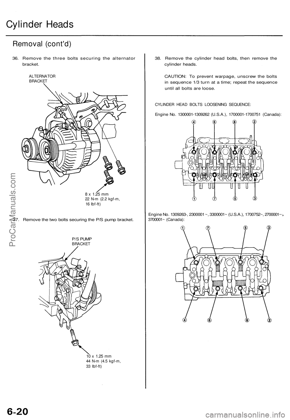
36. Remove the three bolts securing the alternator
bracket.
ALTERNATOR
BRACKET
8 x
1.25
mm
22 N-m (2.2 kgf-m,
16 Ibf-ft)
37. Remove the two bolts securing the P/S pump bracket.
P/S PUMP
BRACKET
10 x
1.25
mm
44 N-m (4.5 kgf-m,
33 Ibf-ft)
38. Remove the cylinder head bolts, then remove the
cylinder heads.
CAUTION: To prevent warpage, unscrew the bolts
in sequence 1/3 turn at a time; repeat the sequence
until all bolts are loose.
CYLINDER HEAD BOLTS LOOSENING SEQUENCE:
Engine No. 1300001-1309262 (U.S.A.), 1700001-1700751 (Canada):
Engine No. 1309263-, 2300001 ~, 3300001~ (U.S.A.), 1700752~, 2700001~
3700001~ (Canada):ProCarManuals.com
Page 97 of 1771
Cylinder Heads
Installation (cont'd)
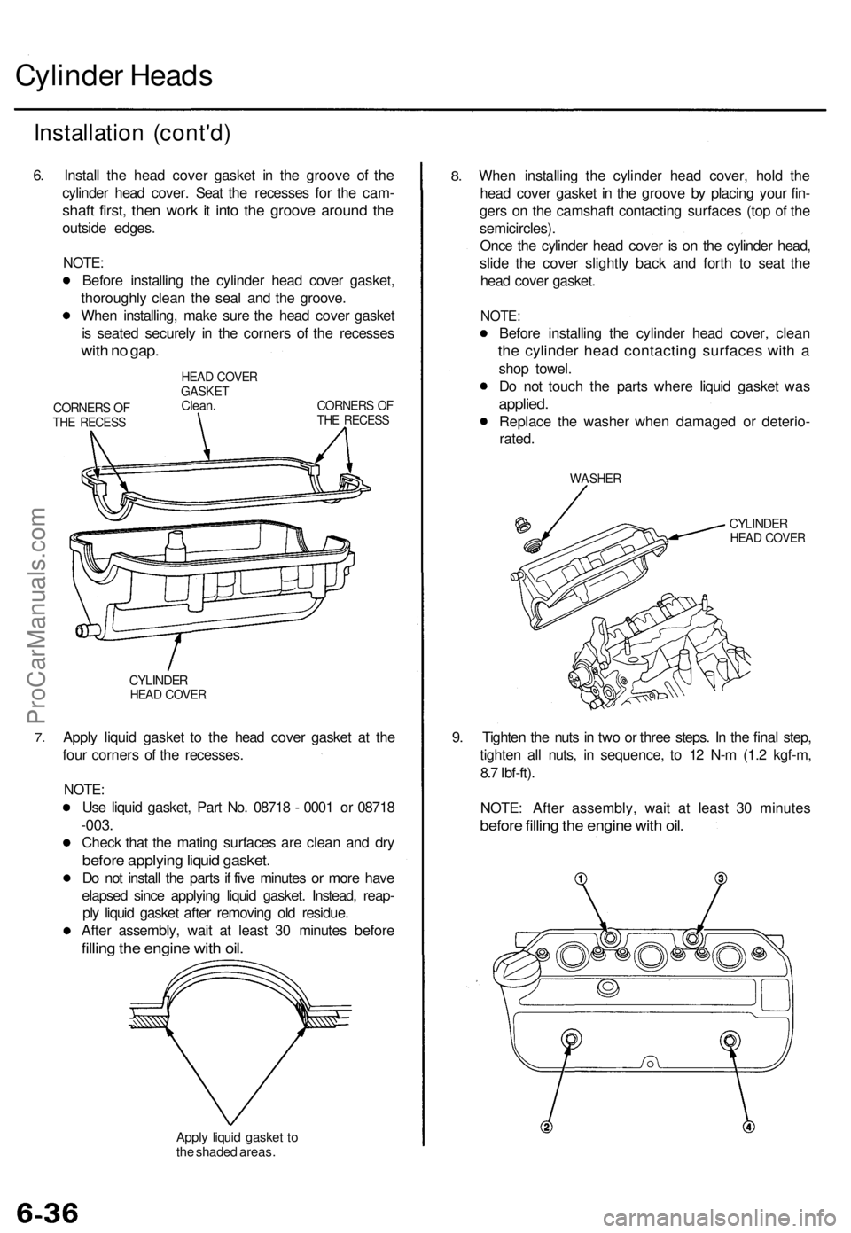
6. Install the head cover gasket in the groove of the
cylinder head cover. Seat the recesses for the cam-
shaft first, then work it into the groove around the
outside edges.
NOTE:
Before installing the cylinder head cover gasket,
thoroughly clean the seal and the groove.
When installing, make sure the head cover gasket
is seated securely in the corners of the recesses
with no gap.
CORNERS OF
THE RECESS
HEAD COVER
GASKET
Clean.
CORNERS OF
THE RECESS
7.
CYLINDER
HEAD COVER
Apply liquid gasket to the head cover gasket at the
four corners of the recesses.
NOTE:
Use liquid gasket, Part No. 08718 - 0001 or 08718
-003.
Check that the mating surfaces are clean and dry
before applying liquid gasket.
Do not install the parts if five minutes or more have
elapsed since applying liquid gasket. Instead, reap-
ply liquid gasket after removing old residue.
After assembly, wait at least 30 minutes before
filling the engine with oil.
Apply liquid gasket to
the shaded areas.
8.
When installing the cylinder head cover, hold the
head cover gasket in the groove by placing your fin-
gers on the camshaft contacting surfaces (top of the
semicircles).
Once the cylinder head cover is on the cylinder head,
slide the cover slightly back and forth to seat the
head cover gasket.
NOTE:
Before installing the cylinder head cover, clean
the cylinder head contacting surfaces with a
shop towel.
Do not touch the parts where liquid gasket was
applied.
Replace the washer when damaged or deterio-
rated.
WASHER
CYLINDER
HEAD COVER
9. Tighten the nuts in two or three steps. In the final step,
tighten all nuts, in sequence, to 12 N-m (1.2 kgf-m,
8.7 Ibf-ft).
NOTE: After assembly, wait at least 30 minutes
before filling the engine with oil.ProCarManuals.com
Page 116 of 1771
Pistons
Installation
Before installing the piston, apply a coat of engine
oil to the ring grooves and cylinder bores.
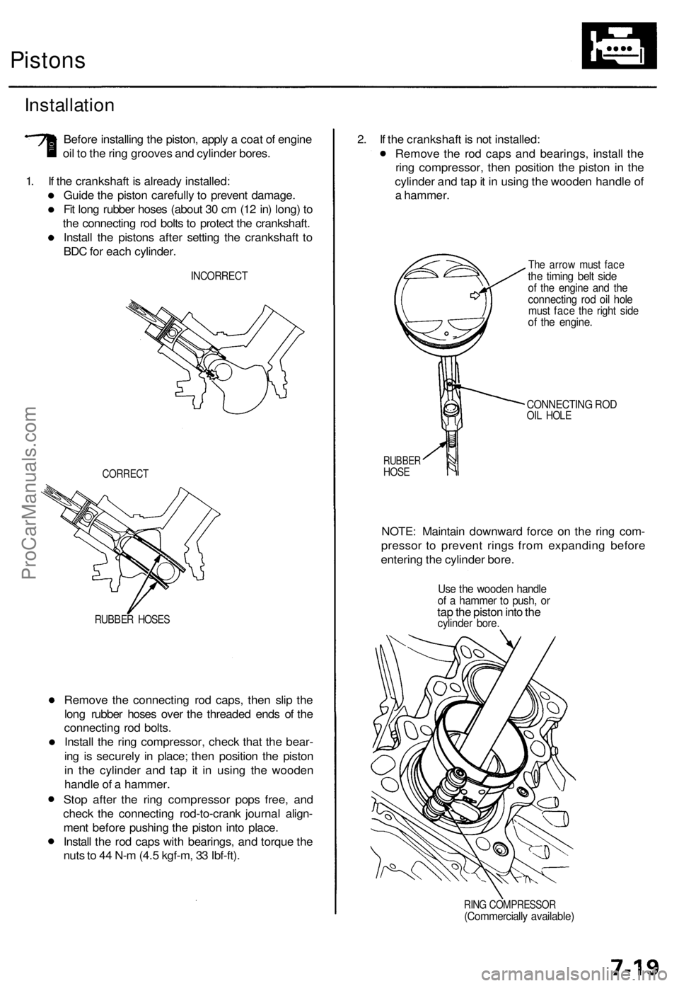
1. If the crankshaft is already installed:
Guide the piston carefully to prevent damage.
Fit long rubber hoses (about 30 cm (12 in) long) to
the connecting rod bolts to protect the crankshaft.
Install the pistons after setting the crankshaft to
BDC for each cylinder.
INCORRECT
CORRECT
RUBBER HOSES
Remove the connecting rod caps, then slip the
long rubber hoses over the threaded ends of the
connecting rod bolts.
Install the ring compressor, check that the bear-
ing is securely in place; then position the piston
in the cylinder and tap it in using the wooden
handle of a hammer.
Stop after the ring compressor pops free, and
check the connecting rod-to-crank journal align-
ment before pushing the piston into place.
Install the rod caps with bearings, and torque the
nuts to 44 N-m (4.5 kgf-m, 33 Ibf-ft).
2. If the crankshaft is not installed:
Remove the rod caps and bearings, install the
ring compressor, then position the piston in the
cylinder and tap it in using the wooden handle of
a hammer.
The arrow must face
the timing belt side
of the engine and the
connecting rod oil hole
must face the right side
of the engine.
CONNECTING ROD
OIL HOLE
RUBBER
HOSE
NOTE: Maintain downward force on the ring com-
pressor to prevent rings from expanding before
entering the cylinder bore.
Use the wooden handle
of a hammer to push, or
tap the piston into the
cylinder bore.
RING COMPRESSOR
(Commercially available)ProCarManuals.com
Page 143 of 1771
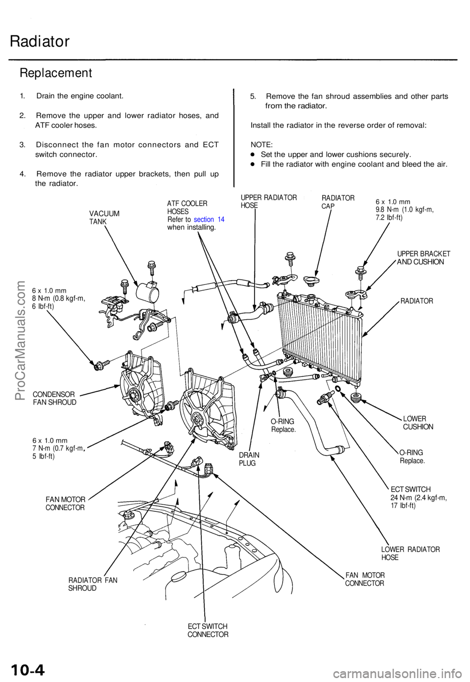
Radiator
5. Remov e th e fa n shrou d assemblie s an d othe r part s
from th e radiator .
Install th e radiato r i n th e revers e orde r o f removal :
NOTE:
Set th e uppe r an d lowe r cushion s securely .
Fil l th e radiato r wit h engin e coolan t an d blee d th e air .
VACUU MTANK
6 x 1. 0 m m8 N- m (0. 8 kgf-m ,6 Ibf-ft )
CONDENSO RFAN SHROU D
6 x 1. 0 m m7 N- m (0. 7 kgf-m ,
5 Ibf-ft )
FAN MOTO RCONNECTO R
RADIATO R FA N
SHROU D
ATF COOLE R
HOSE S
Refe r t o sectio n 1 4
whe n installing .
UPPER RADIATO R
HOS E RADIATO
RCAP6 x 1. 0 m m9.8 N- m (1. 0 kgf-m ,
7. 2 Ibf-ft )
UPPE R BRACKE T
AND CUSHIO N
RADIATO R
LOWE R
CUSHIO N
O-RINGReplace .
ECT SWITC H24 N- m (2. 4 kgf-m ,17 Ibf-ft )
LOWE R RADIATO R
HOS E
FA N MOTO R
CONNECTO R
ECT SWITC HCONNECTO R
DRAINPLUG
O-RIN GReplace .
Replacemen t
1. Drai n th e engin e coolant .
2 . Remov e th e uppe r an d lowe r radiato r hoses , an d
AT F coole r hoses .
3 . Disconnec t th e fa n moto r connector s an d EC T
switc h connector .
4 . Remov e th e radiato r uppe r brackets , the n pul l u p
th e radiator .
ProCarManuals.com
Page 144 of 1771
Engine Coolan t Refillin g an d Bleedin g
CAUTION : Whe n pourin g engin e coolant , b e sur e t o
shu t th e rela y bo x li d an d no t t o le t coolan t spil l o n th e
electrica l part s o r th e paint . I f an y coolan t spills , rins e it
of f immediately .
NOTE:
Perfor m thi s procedur e whe n th e engin e is cool .
Befor e replacin g th e coolant , tur n th e ignitio n O N (II) ,
slowl y tur n th e climat e contro l temperatur e kno b t o
90 ° an d tur n of f th e ignition . Thi s wil l allo w th e
coolan t i n th e heate r t o drai n ou t wit h th e res t o f th e
system .
1 . Mak e sur e yo u hav e th e anti-thef t cod e fo r th e radio ,
the n writ e dow n th e frequencie s fo r th e radio' s pre -
se t buttons .
2 . Disconnec t th e batter y negativ e termina l first , the n
th e positiv e terminal , the n remov e th e batter y an d
batter y bas e (se e pag e 5-4 ).
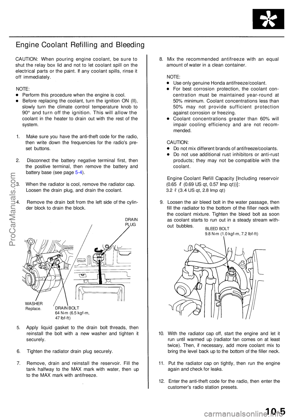
3 . Whe n th e radiato r i s cool , remov e th e radiato r cap .
Loose n th e drai n plug , an d drai n th e coolant .
4 . Remov e th e drai n bol t fro m th e lef t sid e o f th e cylin -
de r bloc k t o drai n th e block .
DRAINPLUG
5.
WASHE RReplace .DRAIN BOL T64 N- m (6. 5 kgf-m ,
4 7 Ibf-ft )
Apply liqui d gaske t t o th e drai n bol t threads , the n
reinstal l th e bol t wit h a ne w washe r an d tighte n i t
securely .
6. Tighte n th e radiato r drai n plu g securely .
7 . Remove , drai n an d reinstal l th e reservoir . Fil l th e
tan k halfwa y t o th e MA X mar k wit h water , the n u p
t o th e MA X mar k wit h antifreeze . 8
. Mi x th e recommende d antifreez e wit h a n equa l
amoun t o f wate r i n a clea n container .
NOTE:
Use onl y genuin e Hond a antifreeze/coolant .
Fo r bes t corrosio n protection , th e coolan t con -
centratio n mus t b e maintaine d year-roun d a t
50 % minimum . Coolan t concentration s les s tha n
50 % ma y no t provid e sufficien t protectio n
agains t corrosio n o r freezing .
Coolan t concentration s greate r tha n 60 % wil l
impai r coolin g efficienc y an d ar e no t recom -
mended .
CAUTION :
D o no t mi x differen t brand s o f antifreeze/coolants .
D o no t us e additiona l rus t inhibitor s o r anti-rus t
products ; the y ma y no t b e compatibl e wit h th e
coolant .
Engine Coolan t Refil l Capacit y [Includin g reservoi r
(0.65 (0.6 9 U S qt , 0.5 7 Im p qt))] :
3.2 (3. 4 US qt , 2. 8 Im p qt )
9. Loose n th e ai r blee d bol t i n th e wate r passage , the n
fill th e radiato r t o th e botto m o f th e fille r nec k wit h
the coolan t mixture . Tighte n th e blee d bol t a s soo n
a s coolan t start s t o ru n ou t i n a stead y strea m with -
ou t bubbles .
10 . Wit h th e radiato r ca p off , star t th e engin e an d le t i t
ru n unti l warme d u p (radiato r fa n come s o n a t leas t
twice) . Then , i f necessary , ad d mor e coolan t mi x t o
brin g th e leve l bac k u p to th e botto m o f th e fille r neck .
11 . Pu t th e radiato r cap on tightly , the n ru n th e engin e
agai n an d chec k fo r leaks .
12 . Ente r th e anti-thef t cod e fo r th e radio , the n ente r th e
customer' s radi o statio n presets .
BLEED BOL T9.8 N- m (1. 0 kgf-m , 7. 2 Ibf-ft )
ProCarManuals.com
Page 200 of 1771
PGM-FI System
System Description (cont'd)
3. Fuel Cut-off Control
During deceleration with the throttle valve closed, current to the fuel injectors is cut off to improve fuel economy at
speeds over 1,000 rpm.
Fuel cut-off action also takes place when engine speed exceeds 6,500 rpm, regardless of the position of the throttle
valve, to protect the engine from over-revving.
4. A/C Compressor Clutch Relay .
When the PCM receives a demand for cooling from the air conditioning system, it delays the compressor from being
energized, and enriches the mixture to assure a smooth transition to the A/C mode.
5. Evaporative Emission (EVAP) Purge Control Solenoid Valve
'96 model: When the engine coolant temperature is below 158°F (70°C), the PCM controls the EVAP purge control
solenoid valve which cuts vacuum to the EVAP purge control canister diaphragm.
'97 - 98 models: When the engine coolant temperature is above 99°F (37°C), the PCM controls the EVAP purge control
solenoid valve which controls vacuum to the EVAP purge control canister.
6. Intake Air Bypass (IAB) Low Control Solenoid Valve, Intake Air Bypass (IAB) High Control Solenoid Valve
When engine speed is below 3,350 rpm, the IAB High Control Solenoid Valve and IAB Low Control Solenoid Valve are
activated by a signal from the PCM. Intake air flows through a long chamber path, increasing torque at low RPM.
When engine speed is 3,350 - 3,950 rpm, the IAB Low Control Solenoid Valve is deactivated by the PCM. Intake air
flows through a short chamber path, increasing mid-range torque.
When the engine rpm is above 3,950 rpm, the IAB Low Control Solenoid Valve and IAB High Control Solenoid Valve are
deactivated by the PCM. This creates a very short intake path and increases high-speed torque.
7. Exhaust Gas Recirculation (EGR) Control Solenoid Valve
When the EGR is required for control of oxides of nitrogen (NOx) emissions, the PCM controls the EGR control solenoid
valve which supplies regulated vacuum to the EGR valve.
ECM Fail-safe/Back-up Functions
1. Fail-safe Function
When an abnormality occurs in a signal from a sensor, the PCM ignores that signal and assumes a pre-programmed
value for that sensor that allows the engine to continue to run.
2. Back-up Function
When an abnormality occurs in the PCM itself, the fuel injectors are controlled by a back-up circuit independent of the
system in order to permit minimal driving.
3. Self-diagnosis Function [Malfunction Indicator Lamp (MIL)]
When an abnormality occurs in a signal from a sensor, the PCM supplies ground for the MIL and stores the DTC in
erasable memory. When the ignition is initially turned on, the PCM supplies ground for the MIL for two seconds to
check the MIL bulb condition.
4. Two Driving Cycle Detection Method
To prevent false indications, the two driving cycle detection method is used for the H02S, fuel metering-related, idle
control system, ECT sensor, EGR system, TWC, EVAP control system and other self-diagnostic functions. When an
abnormality occurs, the PCM stores it in its memory. When the same abnormality recurs after the ignition switch is
turned OFF and ON (II) again, the PCM informs the driver by lighting the MIL.
However, to ease troubleshooting, this function is cancelled when you short the service check connector. The MIL will
then blink immediately when an abnormality occurs.ProCarManuals.com
Page 239 of 1771
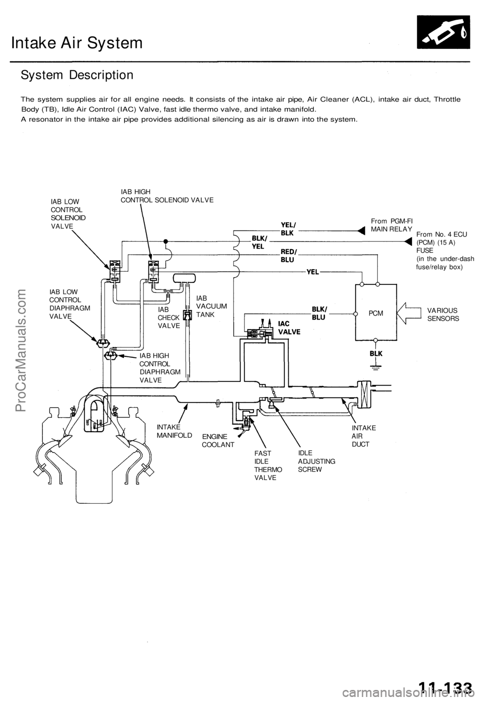
Intake Air System
System Description
The system supplies air for all engine needs. It consists of the intake air pipe, Air Cleaner (ACL), intake air duct, Throttle
Body (TB), Idle Air Control (IAC) Valve, fast idle thermo valve, and intake manifold.
A resonator in the intake air pipe provides additional silencing as air is drawn into the system.
IAB LOW
CONTROL
SOLENOID
VALVE
IAB HIGH
CONTROL SOLENOID VALVE
IAB LOW
CONTROL
DIAPHRAGM
VALVE
From PGM-FI
MAIN RELAY
From No. 4 ECU
(PCM)
(15 A)
FUSE
(in the under-dash
fuse/relay box)
VARIOUS
SENSORS
INTAKE
AIR
DUCT
FAST
IDLE
THERMO
VALVE
IDLE
ADJUSTING
SCREW
ENGINE
COOLANT
INTAKE
MANIFOLD
PCM
IAB
VACUUM
TANK
IAB
CHECK
VALVE
IAB HIGH
CONTROL
DIAPHRAGM
VALVEProCarManuals.com
Page 251 of 1771
Emission Control System
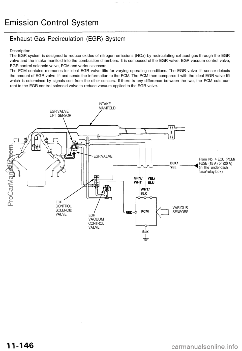
Exhaust Gas Recirculation (EGR) System
Description
The EGR system is designed to reduce oxides of nitrogen emissions (NOx) by recirculating exhaust gas through the EGR
valve and the intake manifold into the combustion chambers. It is composed of the EGR valve, EGR vacuum control valve,
EGR control solenoid valve, PCM and various sensors.
The PCM contains memories for ideal EGR valve lifts for varying operating conditions. The EGR valve lift sensor detects
the amount of EGR valve lift and sends the information to the PCM. The PCM then compares it with the ideal EGR valve lift
which is determined by signals sent from the other sensors. If there is any difference between the two, the PCM cuts cur-
rent to the EGR control solenoid valve to reduce vacuum applied to the EGR valve.
EGR VALVE
LIFT SENSOR
INTAKE
MANIFOLD
From No. 4 ECU (PCM)
FUSE (15 A) or (20 A)
(in the under-dash
fuse/relay box)
EGR
CONTROL
SOLENOID
VALVE
EGR
VACUUM
CONTROL
VALVE
VARIOUS
SENSORS
EGR VALVEProCarManuals.com
Page 253 of 1771
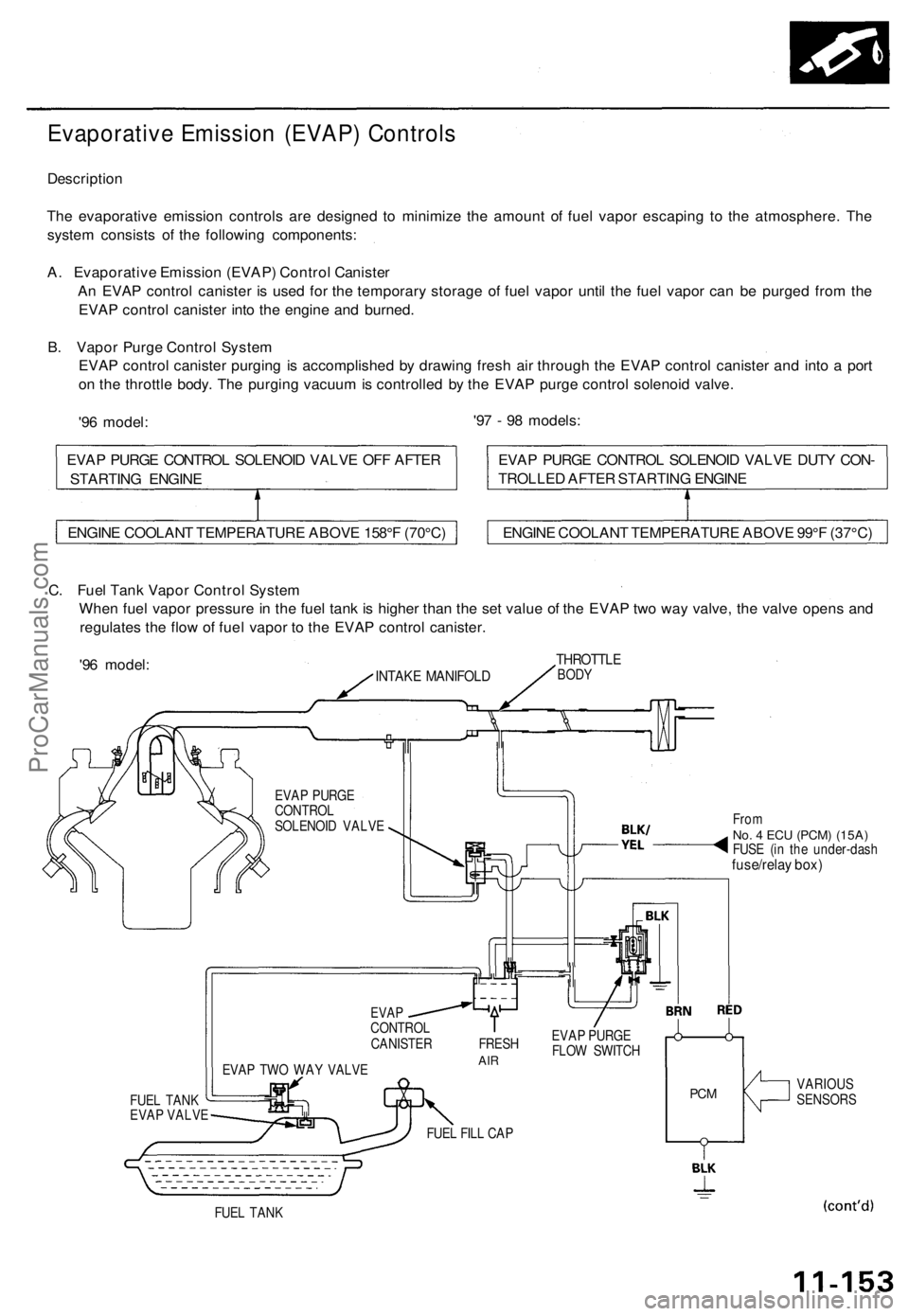
Evaporative Emission (EVAP) Controls
Description
The evaporative emission controls are designed to minimize the amount of fuel vapor escaping to the atmosphere. The
system consists of the following components:
A. Evaporative Emission (EVAP) Control Canister
An EVAP control canister is used for the temporary storage of fuel vapor until the fuel vapor can be purged from the
EVAP control canister into the engine and burned.
B. Vapor Purge Control System
EVAP control canister purging is accomplished by drawing fresh air through the EVAP control canister and into a port
on the throttle body. The purging vacuum is controlled by the EVAP purge control solenoid valve.
'96 model:
'97 - 98 models:
C. Fuel Tank Vapor Control System
When fuel vapor pressure in the fuel tank is higher than the set value of the EVAP two way valve, the valve opens and
regulates the flow of fuel vapor to the EVAP control canister.
'96 model:
INTAKE MANIFOLD
THROTTLE
BODY
EVAP PURGE
CONTROL
SOLENOID VALVE
FUEL TANK
EVAP VALVE
EVAP TWO WAY VALVE
From
No. 4 ECU
(PCM) (15A)
FUSE (in the under-dash
fuse/relay box)
EVAP
CONTROL
CANISTER FRESH
AIR
EVAP PURGE
FLOW SWITCH
FUEL FILL CAP
PCM
VARIOUS
SENSORS
FUEL TANK
ENGINE COOLANT TEMPERATURE ABOVE 158°F (70°C)
ENGINE COOLANT TEMPERATURE ABOVE 99°F (37°C)
EVAP PURGE CONTROL SOLENOID VALVE DUTY CON-
TROLLED AFTER STARTING ENGINE
EVAP PURGE CONTROL SOLENOID VALVE OFF AFTER
STARTING ENGINEProCarManuals.com