reset ACURA TL 1995 Service Repair Manual
[x] Cancel search | Manufacturer: ACURA, Model Year: 1995, Model line: TL, Model: ACURA TL 1995Pages: 1771, PDF Size: 62.49 MB
Page 57 of 1771
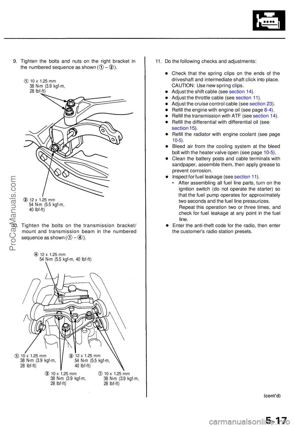
9. Tighte n th e bolt s an d nut s o n th e righ t bracke t i n
th e numbere d sequenc e a s show n ( ) .
10.
12 x 1.2 5 mm54 N- m (5. 5 kgf-m ,
4 0 Ibf-ft )
Tighte n th e bolt s o n th e transmissio n bracket /
moun t an d transmissio n bea m in th e numbere d
sequence a s show n ( ) .
12 x 1.2 5 mm54 N- m (5. 5 kgf-m , 4 0 Ibf-ft )
10 x 1.2 5 mm38 N- m (3. 9 kgf-m ,
2 8 Ibf-ft )
10 x 1.2 5 mm38 N- m (3. 9 kgf-m ,
2 8 Ibf-ft )10 x 1.2 5 mm38 N- m (3. 9 kgf-m ,
2 8 Ibf-ft )
11. D o th e followin g check s an d adjustments :
Chec k tha t th e sprin g clip s o n th e end s o f th e
driveshaf t an d intermediat e shaf t clic k int o place .
CAUTION : Us e ne w sprin g clips .
Adjus t th e shif t cabl e (se e sectio n 14 ).
Adjus t th e throttl e cabl e (se e sectio n 11 ).
Adjus t th e cruis e contro l cabl e (se e sectio n 23 ).
Refil l th e engine with engin e oi l (se e pag e 8-4 ).
Refil l th e transmissio n wit h AT F (se e sectio n 14 ).
Refil l th e differentia l wit h differentia l oi l (se e
sectio n 15 ).
Refil l th e radiato r wit h engine coolant (se e pag e
10-5).
Blee d ai r fro m th e coolin g syste m a t th e blee d
bol t wit h th e heate r valv e ope n (se e pag e 10-5 ).
Clea n th e batter y post s an d cabl e terminal s wit h
sandpaper , assembl e them , the n appl y greas e to
preven t corrosion .
Inspec t fo r fue l leakag e (se e sectio n 11 ).
• Afte r assemblin g al l fue l lin e parts , tur n o n th e
ignitio n switc h (d o no t operat e th e starter ) s o
tha t th e fue l pum p operates for approximatel y
tw o second s an d th e fue l lin e pressurizes .
Repea t thi s operatio n tw o o r thre e times , an d
chec k fo r fue l leakag e a t an y poin t i n th e fue l
line.
Ente r th e anti-thef t cod e fo r th e radio , the n ente r
th e customer' s radi o statio n presets .
12 x 1.2 5 mm54 N- m (5. 5 kgf-m ,
4 0 Ibf-ft )
10 x 1.2 5 mm38 N- m (3. 9 kgf-m ,
2 8 Ibf-ft )
ProCarManuals.com
Page 68 of 1771
Timing Bel t
Installatio n (cont'd )
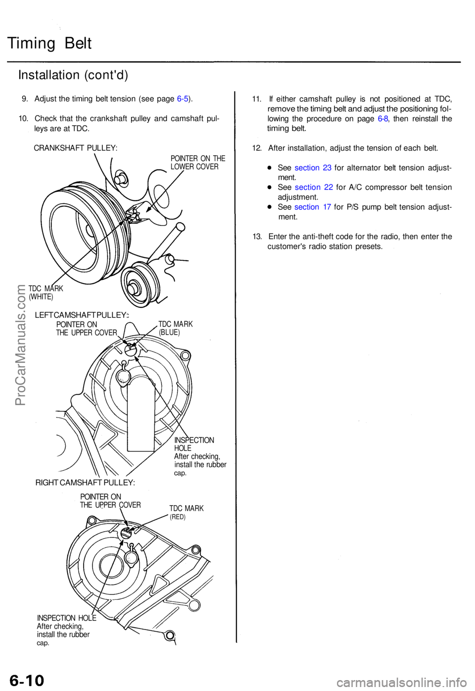
9. Adjus t th e timin g bel t tensio n (se e pag e 6-5 ).
10 . Chec k tha t th e crankshaf t pulle y an d camshaf t pul -
ley s ar e a t TDC .
CRANKSHAF T PULLEY :
TDC MAR K
(WHITE )
LEFT CAMSHAF T PULLEY :
POINTER O NTH E UPPE R COVE R
RIGHT CAMSHAF T PULLEY :
POINTER O NTH E UPPE R COVE R POINTE
R O N TH E
LOWE R COVE R
TD C MAR K
(BLUE )
INSPECTIO NHOLEAfter checking ,install th e rubbe rcap.
TDC MAR K(RED)
INSPECTIO N HOL EAfter checking ,install th e rubbe rcap.
11. I f eithe r camshaf t pulle y i s no t positione d a t TDC ,
remov e th e timin g bel t an d adjus t th e positionin g fol -
lowin g th e procedur e o n pag e 6-8 , the n reinstal l th e
timin g belt .
12. Afte r installation , adjus t th e tensio n o f eac h belt .
Se e sectio n 2 3 fo r alternato r bel t tensio n adjust -
ment .
Se e sectio n 2 2 fo r A/ C compresso r bel t tensio n
adjustment .
Se e sectio n 1 7 fo r P/ S pum p bel t tensio n adjust -
ment .
13 . Ente r th e anti-theft code fo r th e radio , the n ente r th e
customer' s radi o statio n presets .
ProCarManuals.com
Page 96 of 1771
Cylinder Heads
Installation
Install th e cylinde r head s in th e revers e orde r o f removal .
NOTE:
Alway s us e ne w cylinde r hea d gaskets .
Cylinde r head s an d cylinde r bloc k surfac e mus t b e
clean .
Turn th e camshaft s s o th e pulle y locatin g pi n hole s
are a t th e top .
Turn th e crankshaf t s o th e No . 1 pisto n is a t TD C (se e
pag e 6-8 ).
Clea n th e oi l contro l orifice s befor e installing .
D o no t us e th e uppe r an d lowe r cover s t o stor e
remove d item .
Clea n th e uppe r an d lowe r cover s befor e installation .
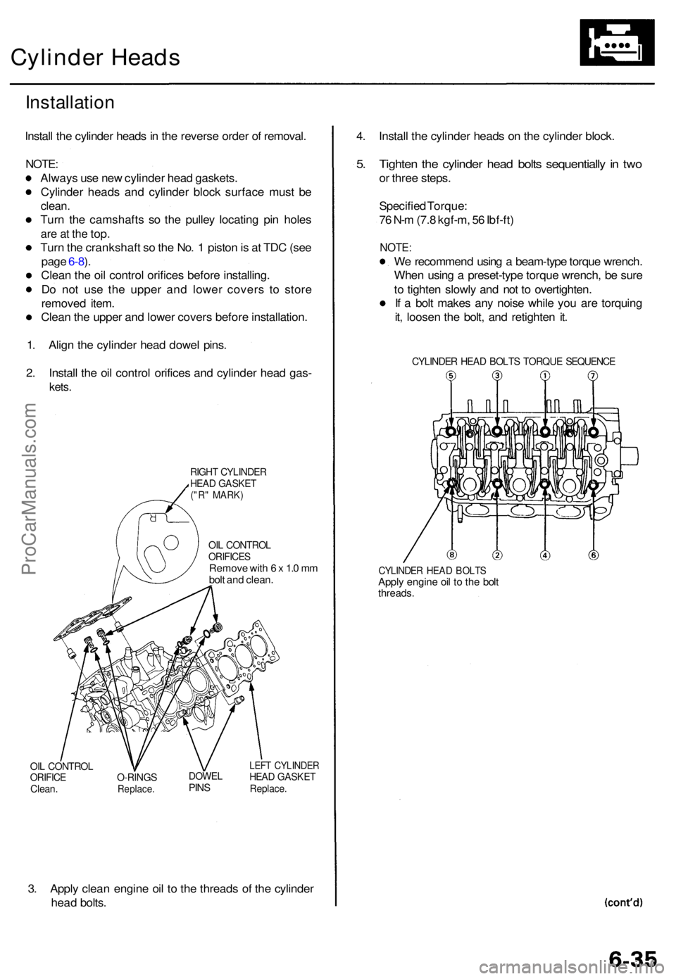
1 . Alig n th e cylinde r hea d dowe l pins .
2 . Instal l th e oi l contro l orifice s an d cylinde r hea d gas -
kets.
RIGH T CYLINDE RHEAD GASKE T("R" MARK )
OIL CONTRO LORIFICESRemove wit h 6 x 1. 0 m m
bol t an d clean .
OIL CONTRO LORIFICEClean.O-RING SReplace .
DOWELPINS
LEF T CYLINDE RHEAD GASKE TReplace.
3. Appl y clea n engin e oi l t o th e thread s o f th e cylinde r
hea d bolts . 4
. Instal l th e cylinde r head s o n th e cylinde r block .
5. Tighte n th e cylinde r hea d bolt s sequentiall y in tw o
or thre e steps .
Specifie d Torque :
7 6 N- m (7. 8 kgf-m , 5 6 Ibf-ft )
NOTE :
We recommen d usin g a beam-typ e torqu e wrench .
Whe n usin g a preset-typ e torqu e wrench , b e sur e
t o tighte n slowl y an d no t t o overtighten .
I f a bol t make s an y nois e whil e yo u ar e torquin g
it , loose n th e bolt , an d retighte n it .
CYLINDE R HEA D BOLT S TORQU E SEQUENC E
CYLINDER HEA D BOLT SApply engin e oi l t o th e bol tthreads .
ProCarManuals.com
Page 98 of 1771
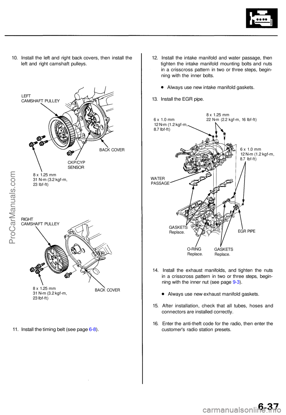
10. Instal l th e lef t an d righ t bac k covers , the n instal l th e
lef t an d righ t camshaf t pulleys .
LEFTCAMSHAF T PULLE Y
BACK COVE R
CKP/CY PSENSOR
8 x 1.2 5 mm31 N- m (3. 2 kgf-m ,23 Ibf-ft )
RIGHTCAMSHAF T PULLE Y
8 x 1.2 5 mm31 N- m (3. 2 kgf-m ,
2 3 Ibf-ft )BACK COVE R
11. Instal l th e timin g bel t (se e pag e 6-8 ).
12 . Instal l th e intak e manifol d an d wate r passage , the n
tighte n th e intak e manifol d mountin g bolt s an d nut s
i n a crisscros s patter n i n tw o o r thre e steps , begin -
nin g wit h th e inne r bolts .
Alway s us e ne w intak e manifol d gaskets .
13 . Instal l th e EG R pipe .
6 x 1. 0 m m12 N- m (1. 2 kgf-m ,
8. 7 Ibf-ft )
8 x 1.2 5 mm22 N- m (2. 2 kgf-m , 1 6 Ibf-ft )
WATE RPASSAG E
6 x 1. 0 m m12 N- m (1. 2 kgf-m ,8.7 Ibf-ft )
GASKET SReplace.EGR PIP E
O-RIN GReplace .GASKET SReplace.
14. Instal l th e exhaus t manifolds , an d tighte n th e nut s
i n a crisscros s patter n i n tw o o r thre e steps , begin -
nin g wit h th e inne r nu t (se e pag e 9-3 ).
Alway s us e ne w exhaus t manifol d gaskets .
15 . Afte r installation , chec k tha t al l tubes , hose s an d
connector s ar e installe d correctly .
16 . Ente r th e anti-thef t cod e fo r th e radio , the n ente r th e
customer' s radi o statio n presets .
ProCarManuals.com
Page 144 of 1771
Engine Coolan t Refillin g an d Bleedin g
CAUTION : Whe n pourin g engin e coolant , b e sur e t o
shu t th e rela y bo x li d an d no t t o le t coolan t spil l o n th e
electrica l part s o r th e paint . I f an y coolan t spills , rins e it
of f immediately .
NOTE:
Perfor m thi s procedur e whe n th e engin e is cool .
Befor e replacin g th e coolant , tur n th e ignitio n O N (II) ,
slowl y tur n th e climat e contro l temperatur e kno b t o
90 ° an d tur n of f th e ignition . Thi s wil l allo w th e
coolan t i n th e heate r t o drai n ou t wit h th e res t o f th e
system .
1 . Mak e sur e yo u hav e th e anti-thef t cod e fo r th e radio ,
the n writ e dow n th e frequencie s fo r th e radio' s pre -
se t buttons .
2 . Disconnec t th e batter y negativ e termina l first , the n
th e positiv e terminal , the n remov e th e batter y an d
batter y bas e (se e pag e 5-4 ).
3 . Whe n th e radiato r i s cool , remov e th e radiato r cap .
Loose n th e drai n plug , an d drai n th e coolant .
4 . Remov e th e drai n bol t fro m th e lef t sid e o f th e cylin -
de r bloc k t o drai n th e block .
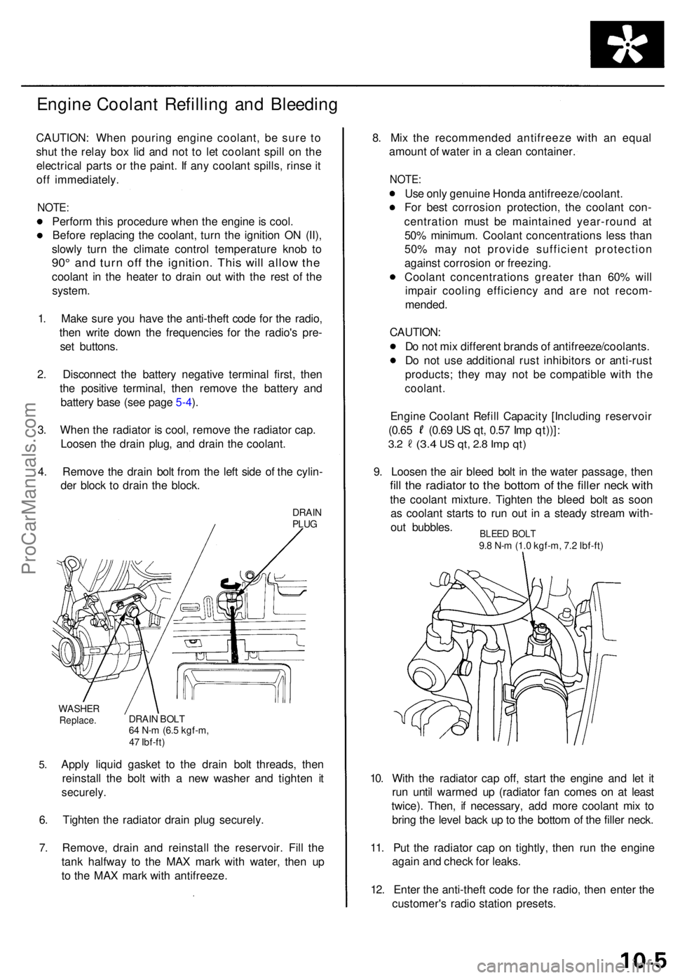
DRAINPLUG
5.
WASHE RReplace .DRAIN BOL T64 N- m (6. 5 kgf-m ,
4 7 Ibf-ft )
Apply liqui d gaske t t o th e drai n bol t threads , the n
reinstal l th e bol t wit h a ne w washe r an d tighte n i t
securely .
6. Tighte n th e radiato r drai n plu g securely .
7 . Remove , drai n an d reinstal l th e reservoir . Fil l th e
tan k halfwa y t o th e MA X mar k wit h water , the n u p
t o th e MA X mar k wit h antifreeze . 8
. Mi x th e recommende d antifreez e wit h a n equa l
amoun t o f wate r i n a clea n container .
NOTE:
Use onl y genuin e Hond a antifreeze/coolant .
Fo r bes t corrosio n protection , th e coolan t con -
centratio n mus t b e maintaine d year-roun d a t
50 % minimum . Coolan t concentration s les s tha n
50 % ma y no t provid e sufficien t protectio n
agains t corrosio n o r freezing .
Coolan t concentration s greate r tha n 60 % wil l
impai r coolin g efficienc y an d ar e no t recom -
mended .
CAUTION :
D o no t mi x differen t brand s o f antifreeze/coolants .
D o no t us e additiona l rus t inhibitor s o r anti-rus t
products ; the y ma y no t b e compatibl e wit h th e
coolant .
Engine Coolan t Refil l Capacit y [Includin g reservoi r
(0.65 (0.6 9 U S qt , 0.5 7 Im p qt))] :
3.2 (3. 4 US qt , 2. 8 Im p qt )
9. Loose n th e ai r blee d bol t i n th e wate r passage , the n
fill th e radiato r t o th e botto m o f th e fille r nec k wit h
the coolan t mixture . Tighte n th e blee d bol t a s soo n
a s coolan t start s t o ru n ou t i n a stead y strea m with -
ou t bubbles .
10 . Wit h th e radiato r ca p off , star t th e engin e an d le t i t
ru n unti l warme d u p (radiato r fa n come s o n a t leas t
twice) . Then , i f necessary , ad d mor e coolan t mi x t o
brin g th e leve l bac k u p to th e botto m o f th e fille r neck .
11 . Pu t th e radiato r cap on tightly , the n ru n th e engin e
agai n an d chec k fo r leaks .
12 . Ente r th e anti-thef t cod e fo r th e radio , the n ente r th e
customer' s radi o statio n presets .
BLEED BOL T9.8 N- m (1. 0 kgf-m , 7. 2 Ibf-ft )
ProCarManuals.com
Page 181 of 1771
II. Powertrain Control Module (PCM) Reset Procedure
Either of the following actions will reset the PCM
Use the OBD II scan tool or Honda PGM Tester to clear the PCM's memory.
NOTE: See the OBD II scan tool or Honda PGM Tester user's manuals for specific operating instructions.
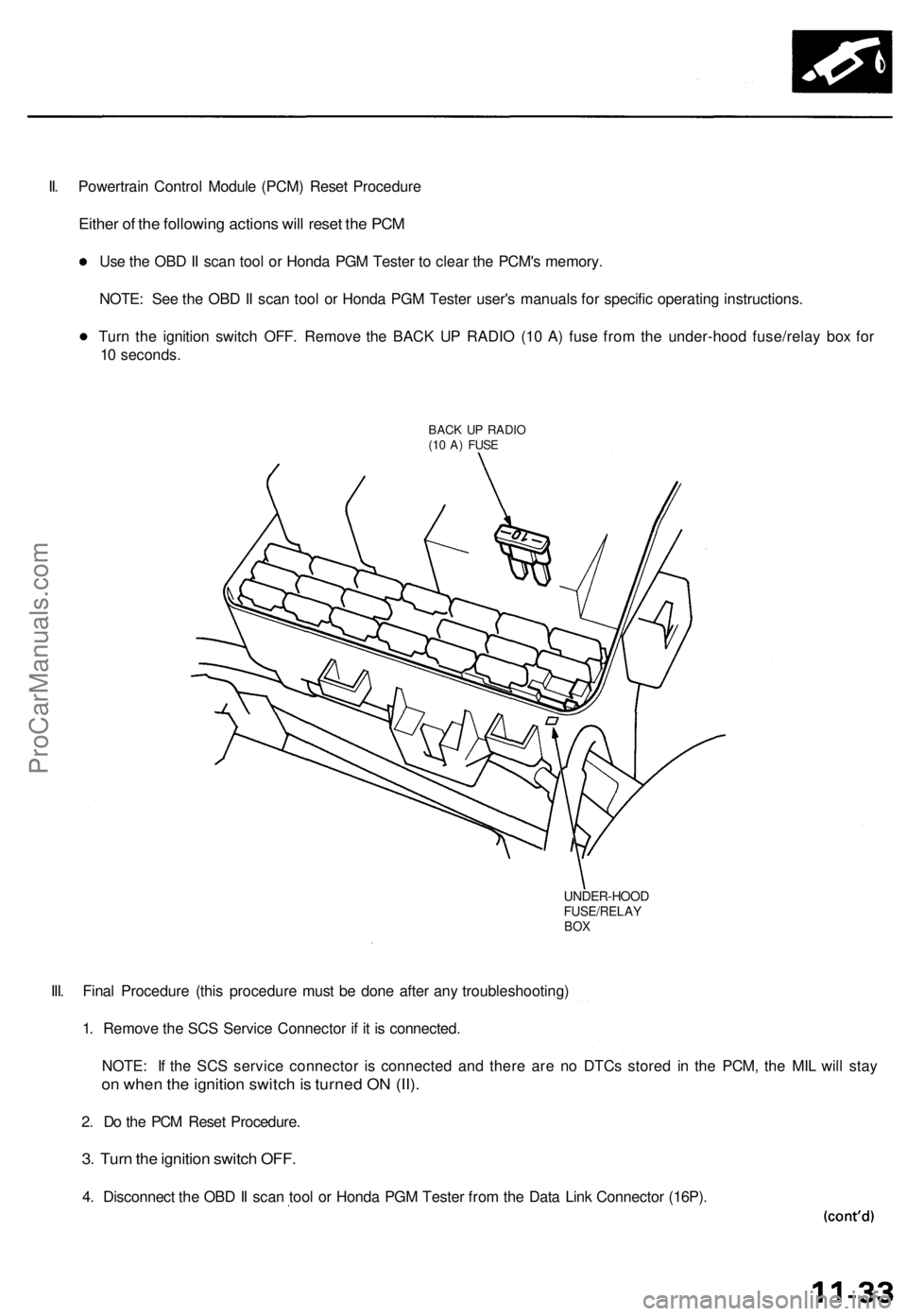
Turn the ignition switch OFF. Remove the BACK UP RADIO (10 A) fuse from the under-hood fuse/relay box for
10 seconds.
BACK UP RADIO
(10 A) FUSE
UNDER-HOOD
FUSE/RELAY
BOX
III. Final Procedure (this procedure must be done after any troubleshooting)
1. Remove the SCS Service Connector if it is connected.
NOTE: If the SCS service connector is connected and there are no DTCs stored in the PCM, the MIL will stay
on when the ignition switch is turned ON (II).
2. Do the PCM Reset Procedure.
3. Turn the ignition switch OFF.
4. Disconnect the OBD II scan tool or Honda PGM Tester from the Data Link Connector (16P).ProCarManuals.com
Page 198 of 1771
Troubleshooting
How to Read Flowcharts
A flowchart is designed to be used from start to final repair. It's like a map showing you the shortest distance. But beware:
if you go off the "map" anywhere but a "stop" symbol, you can easily get lost.
Describes the conditions or situation to start a troubleshooting flowchart.
Asks you to do something; perform a test, set up a condition etc.
Asks you about the result of an action, then sends you in the appropriate troubleshooting direction.
The end of a series of actions and decisions, describes a final repair action and sometimes directs you to
an earlier part of the flowchart to confirm your repair.
NOTE:
The term "Intermittent Failure" is used in these charts. It simply means a system may have had a failure, but it checks
out OK at this time. If the Malfunction Indicator Lamp (MIL) on the dash does not come on, check for poor connections
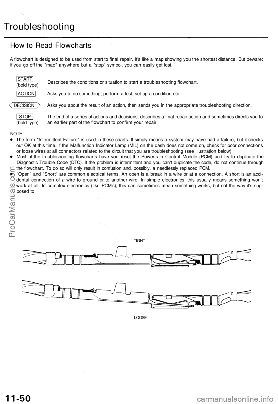
or loose wires at all connectors related to the circuit that you are troubleshooting (see illustration below).
Most of the troubleshooting flowcharts have you reset the Powertrain Control Module (PCM) and try to duplicate the
Diagnostic Trouble Code (DTC). If the problem is intermittent and you can't duplicate the code, do not continue through
the flowchart. To do so will only result in confusion and, possibly, a needlessly replaced PCM.
"Open" and "Short" are common electrical terms. An open is a break in a wire or at a connection. A short is an acci-
dental connection of a wire to ground or to another wire. In simple electronics, this usually means something won't
work at all. In complex electronics (like PCM's), this can sometimes mean something works, but not the way it's sup-
posed to.
TIGHT
LOOSE
(bold type)
STOP
DECISION
ACTION
(bold type)
STARTProCarManuals.com
Page 305 of 1771
Troubleshooting Procedure s
Checking th e Diagnosti c Troubl e Cod e (DTC )
wit h a n OB D II Sca n too l o r Hond a PG M Teste r
When th e PC M sense s a n abnormalit y i n th e inpu t o r outpu t systems , th e indicato r ligh t i n th e gaug e assembl y wil l
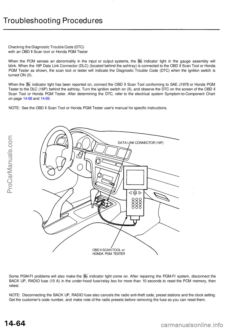
blink . Whe n th e 16 P Dat a Lin k Connecto r (DLC ) (locate d behin d th e ashtray ) i s connecte d to th e OB D II Sca n Too l o r Hond a
PG M Teste r a s shown , th e sca n too l o r teste r wil l indicat e th e Diagnosti c Troubl e Cod e (DTC ) whe n th e ignitio n switc h i s
turne d O N (II) .
Whe n th e indicato r ligh t ha s bee n reporte d on , connec t th e OB D II Sca n Too l conformin g t o SA E J197 8 o r Hond a PG M
Teste r t o th e DL C (16P ) behin d th e ashtray . Tur n th e ignitio n switc h o n (II) , an d observ e th e DT C o n th e scree n o f th e OB D II
Sca n Too l o r Hond a PG M Tester . Afte r determinin g th e DTC , refe r t o th e electrica l syste m Symptom-to-Componen t Char t
o n pag e 14-6 8 an d 14-69 .
NOTE : Se e th e OB D II Sca n Too l o r Hond a PG M Teste r user' s manua l fo r specifi c instructions .
DATA LIN K CONNECTO R (16P )
OBD II SCA N TOO L o r
HOND A PG M TESTE R
Some PGM-F I problem s wil l als o mak e th e indicator light com e on . Afte r repairin g th e PGM-F I system , disconnec t th e
BAC K UP , RADI O fus e (1 0 A ) i n th e under-hoo d fuse/rela y bo x fo r mor e tha n 1 0 second s t o rese t th e PC M memory , the n
retest .
NOTE : Disconnectin g th e BAC K UP , RADI O fus e als o cancel s th e radi o anti-thef t code , prese t station s an d th e cloc k setting .
Ge t th e customer' s cod e number , an d mak e not e o f th e radi o preset s befor e removin g th e fus e s o yo u ca n rese t them .
ProCarManuals.com
Page 306 of 1771
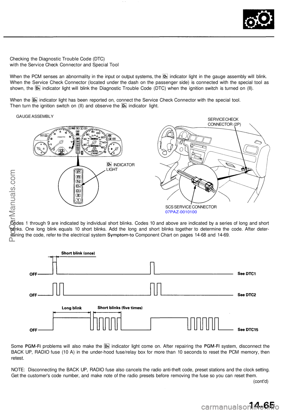
Checking th e Diagnosti c Troubl e Cod e (DTC )
wit h th e Servic e Chec k Connecto r an d Specia l Too l
Whe n th e PC M sense s a n abnormalit y i n th e inpu t o r outpu t systems , th e indicato r ligh t i n th e gaug e assembl y wil l blink .
Whe n th e Servic e Chec k Connecto r (locate d unde r th e das h o n th e passenge r side ) i s connecte d wit h th e specia l too l a s
shown , th e indicato r ligh t wil l blin k th e Diagnosti c Troubl e Cod e (DTC ) whe n th e ignitio n switc h i s turne d o n (II) .
Whe n th e indicato r ligh t ha s bee n reporte d on , connec t th e Servic e Chec k Connecto r wit h th e specia l tool .
Then tur n th e ignitio n switc h o n (II ) an d observ e th e indicato r light .
GAUG E ASSEMBL Y
SERVICE CHEC K
CONNECTO R (2P )
INDICATO R
LIGH T
SCS SERVIC E CONNECTO R07PAZ-001010 0
Codes 1 throug h 9 ar e indicate d b y individua l shor t blinks . Code s 1 0 an d abov e ar e indicate d b y a serie s o f lon g an d shor t
blinks . On e lon g blin k equal s 1 0 shor t blinks . Ad d th e lon g an d shor t blink s togethe r t o determin e th e code . Afte r deter -
mining th e code , refe r to th e electrica l syste m Symptom-t o Component Char t o n page s 14-6 8 an d 14-69 .
Some PGM-F I problem s wil l als o mak e th e indicato r ligh t com e on . Afte r repairin g th e PGM-F I system, disconnec t th e
BAC K UP , RADI O fus e (1 0 A ) i n th e under-hoo d fuse/rela y bo x fo r mor e tha n 1 0 second s t o rese t th e PC M memory , the n
retest .
NOTE : Disconnectin g th e BAC K UP , RADI O fus e als o cancel s th e radi o anti-thef t code , prese t station s an d th e cloc k setting .
Ge t th e customer' s cod e number , an d mak e not e o f th e radi o preset s befor e removin g th e fus e s o yo u ca n rese t them .
(cont'd )
ProCarManuals.com
Page 308 of 1771
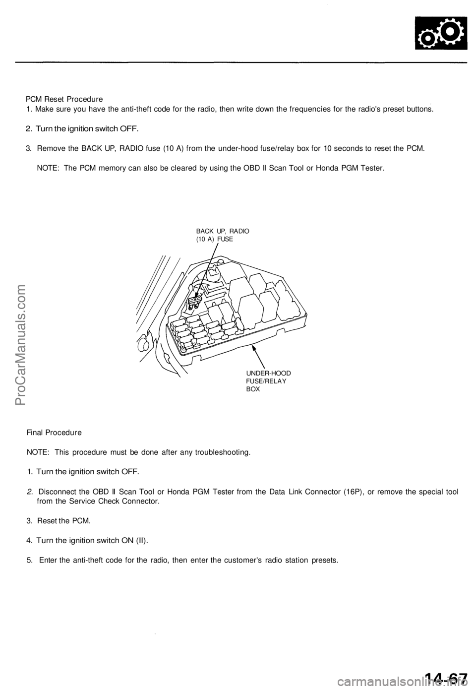
PCM Reset Procedure
1. Make sure you have the anti-theft code for the radio, then write down the frequencies for the radio's preset buttons.
2. Turn the ignition switch OFF.
3. Remove the BACK UP, RADIO fuse (10 A) from the under-hood fuse/relay box for 10 seconds to reset the PCM.
NOTE: The PCM memory can also be cleared by using the OBD II Scan Tool or Honda PGM Tester.
BACK UP, RADIO
(10 A) FUSE
UNDER-HOOD
FUSE/RELAY
BOX
Final Procedure
NOTE: This procedure must be done after any troubleshooting.
1. Turn the ignition switch OFF.
2. Disconnect the OBD II Scan Tool or Honda PGM Tester from the Data Link Connector (16P), or remove the special tool
from the Service Check Connector.
3. Reset the PCM.
4. Turn the ignition switch ON (II).
5. Enter the anti-theft code for the radio, then enter the customer's radio station presets.ProCarManuals.com