sensor Acura TL 2002 3.2 Owner's Manual
[x] Cancel search | Manufacturer: ACURA, Model Year: 2002, Model line: TL, Model: Acura TL 2002Pages: 339, PDF Size: 4.71 MB
Page 50 of 339
Your Supplemental Restraint System
(SRS) includes:An indicator light on the
instrument panel that alerts you to
a possible problem with the
system (see page ).
Two f ront airbags. The driver’s
airbag is stored in the center of
the steering wheel; the f ront
passenger’sairbagisstoredinthe
dashboard. Both are marked ‘‘SRS
AIRBAG.’’ Emergency backup power in case
your car’s electrical system is
disconnected in a crash.
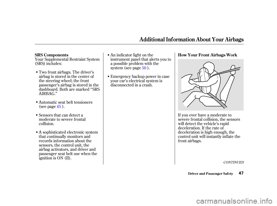
If you ever have a moderate to
severe f rontal collision, the sensors
will detect the vehicle’s rapid
deceleration. If the rate of
deceleration is high enough, the
control unit will instantly inf late the
f ront airbags.
A sophisticated electronic system
that continually monitors and
records inf ormation about the
sensors, the control unit, the
airbag activators, and driver and
passenger seat belt use when the
ignition is ON (II). Sensors that can detect a
moderate to severe frontal
collision. Automatic seat belt tensioners
(see page ).
45 50
CONT INUED
SRS Components
How Your Front A irbags Work
Driver and Passenger Saf ety
Additional Inf ormation About Your Airbags
47
00/12/25 14:01:08 31S0K630_050
Page 51 of 339
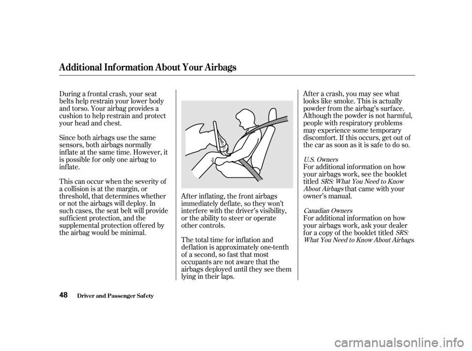
The total time for inflation and
def lation is approximately one-tenth
of a second, so f ast that most
occupants are not aware that the
airbags deployed until they see them
lying in their laps.After a crash, you may see what
looks like smoke. This is actually
powder f rom the airbag’s surf ace.
Although the powder is not harmf ul,
people with respiratory problems
may experience some temporary
discomf ort. If this occurs, get out of
the car as soon as it is safe to do so.
For additional information on how
your airbags work, see the booklet
titled
that came with your
owner’s manual.
Since both airbags use the same
sensors, both airbags normally
inf late at the same time. However, it
is possible f or only one airbag to
inf late.
This can occur when the severity of
a collision is at the margin, or
threshold, that determines whether
or not the airbags will deploy. In
such cases, the seat belt will provide
suf f icient protection, and the
supplemental protection of f ered by
the airbag would be minimal.
Af ter inf lating, the f ront airbags
immediately def late, so they won’t
interf ere with the driver’s visibility,
or the ability to steer or operate
other controls.
For additional information on how
your airbags work, ask your dealer
f or a copy of the booklet titled
During a f rontal crash, your seat
belts help restrain your lower body
and torso. Your airbag provides a
cushion to help restrain and protect
your head and chest.
SRS: What You Need to Know
About Airbags
SRS:
What You Need to Know About Airbags
.
U.S. Owners
Canadian Owners
Driver and Passenger Saf ety
Additional Inf ormation About Your Airbags
48
00/12/25 14:01:18 31S0K630_051
Page 52 of 339
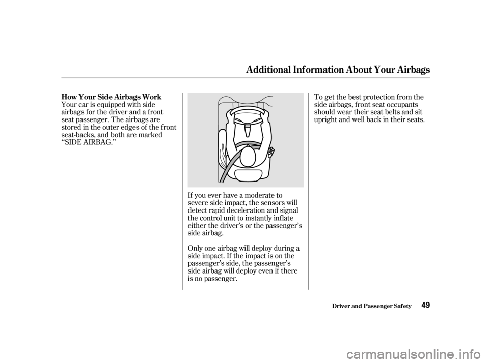
To get the best protection f rom the
side airbags, front seat occupants
should wear their seat belts and sit
upright and well back in their seats.
Your car is equipped with side
airbags f or the driver and a f ront
seat passenger. The airbags are
stored in the outer edges of the f ront
seat-backs, and both are marked
‘‘SIDE AIRBAG.’’
If you ever have a moderate to
severe side impact, the sensors will
detect rapid deceleration and signal
the control unit to instantly inf late
either the driver’s or the passenger’s
side airbag.
Only one airbag will deploy during a
side impact. If the impact is on the
passenger’s side, the passenger’s
side airbag will deploy even if there
is no passenger.
How Your Side A irbags Work
Driver and Passenger Saf ety
Additional Inf ormation About Your Airbags
49
00/12/25 14:01:26 31S0K630_052
Page 69 of 339

This shows how much f uel you have.
It is most accurate when the car is on
level ground. It may show slightly
more or less than the actual amount
whenyouaredrivingoncurvyor
hilly roads.
The needle returns to the bottom
after you turn off the ignition. The
gauge shows the f uel level reading
immediately af ter you turn the
ignition switch back ON (II).
This shows the temperature of the
engine’s coolant. During normal
operation, the pointer should rise
from the bottom white mark to about
the middle of the gauge. In severe
driving conditions, such as very hot
weather or a long period of uphill
driving, the pointer may rise to near
the upper red mark. If it reaches the
red (Hot) mark, pull saf ely to the
side of the road. Turn to page f or
instructions and precautions on
checking the engine’s cooling
system.
This indicator displays the outside
temperature in Fahrenheit in U.S.
models, and in Centigrade in
Canadian models.
The temperature sensor is located in
the f ront bumper. Theref ore, the
temperature reading can be af f ected
by heat ref lection f rom the road sur-
f ace, engine heat, and the exhaust
f rom the surrounding traf f ic. This
can cause the temperature reading
not to be correct when your speed is
under 19 mph (30 km/h).
In certain weather conditions,
temperature readings near f reezing
(32°F, 0°C) could mean that ice is
f orming on the road surf ace.
289
Inst rument s and Cont rols
Gauges
Fuel Gauge
Temperature Gauge
Outside Temperature Indicator
66
00/12/25 14:04:40 31S0K630_069
Page 102 of 339
The HI or LO indicator lights and
remains lit until you turn it of f by
pushing the opposite side of the
switch lightly. The indicator will turn
off.
In HI, the heater turns of f when the
seat gets warm, and turns back on
after the seat’s temperature drops. It
continues to cycle as long as you
leave it set on HI. The HI indicator
remains lit as a reminder that you
have the heater on.
In LO, the heater runs continuously.
It does not cycle with temperature
changes.
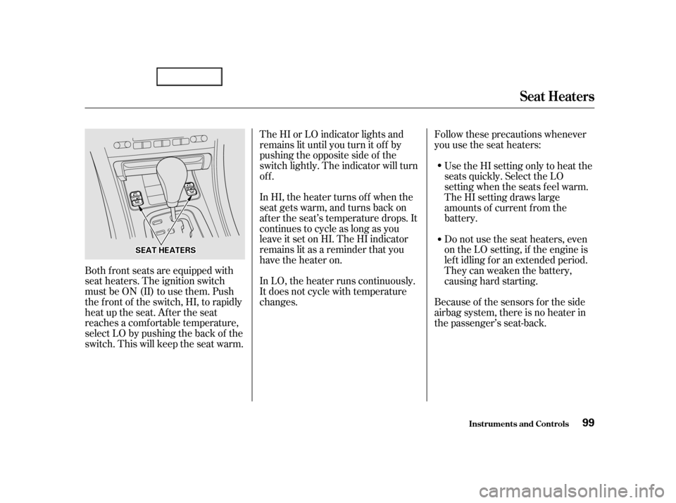
Both f ront seats are equipped with
seat heaters. The ignition switch
must be ON (II) to use them. Push
the front of the switch, HI, to rapidly
heat up the seat. After the seat
reaches a comf ortable temperature,
select LO by pushing the back of the
switch. This will keep the seat warm. Follow these precautions whenever
you use the seat heaters:
Do not use the seat heaters, even
on the LO setting, if the engine is
lef t idling f or an extended period.
They can weaken the battery,
causing hard starting. Use the HI setting only to heat the
seats quickly. Select the LO
setting when the seats f eel warm.
The HI setting draws large
amounts of current f rom the
battery.
Because of the sensors f or the side
airbag system, there is no heater in
the passenger’s seat-back.
Seat Heaters
Inst rument s and Cont rols99
S SE EA
A T
T H
HE
EA
A T
TE
ER
RS S
00/12/25 14:10:17 31S0K630_102
Page 118 of 339
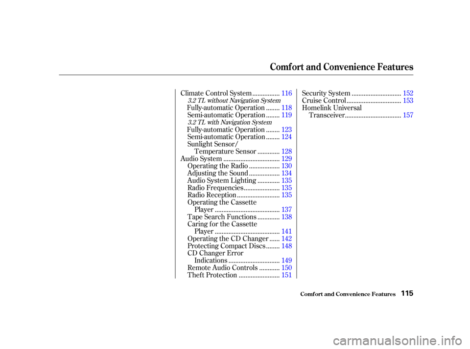
...............
Climate Control System . 116
.......
Fully-automatic Operation . 118
.......
Semi-automatic Operation . 119
.......
Fully-automatic Operation . 123
.......
Semi-automatic Operation . 124
Sunlight Sensor/ ............
Temperature Sensor . 128
................................
Audio System .129
.................
Operating the Radio . 130
.................
Adjusting the Sound . 134
............
Audio System Lighting . 135
....................
Radio Frequencies . 135
........................
Radio Reception .135
Operating the Cassette .....................................
Player .137
............
Tape Search Functions . 138
Caring f or the Cassette .....................................
Player .141
.....
Operating the CD Changer . 142
.......
Protecting Compact Discs . 148
CD Changer Error .............................
Indications .149
...........
Remote Audio Controls . 150
.......................
Thef t Protection .151 ............................
Security System .152
...............................
Cruise Control .153
Homelink Universal ................................
Transceiver .157
3.2 TL without Navigation System
3.2 TL with Navigation System
Comf ort and Convenience Features
Comf ort and Convenience Feat ures115
00/12/25 14:12:31 31S0K630_118
Page 131 of 339
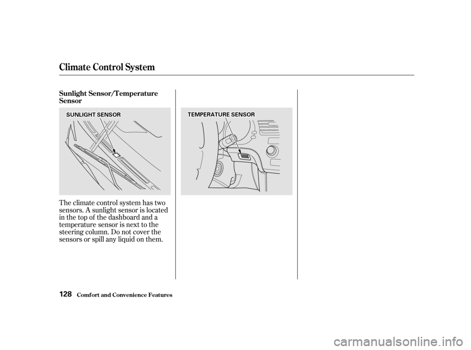
Theclimatecontrolsystemhastwo
sensors. A sunlight sensor is located
in the top of the dashboard and a
temperature sensor is next to the
steering column. Do not cover the
sensors or spill any liquid on them. Sunlight Sensor/T emperature
Sensor
Climat e Cont rol Syst em
Comf ort and Convenience Feat ures128
T TE
EM
M P
PE
ER
RA A T
TU
UR REE S
SEEN
NS SOOR R
S
SU UN NLLIIGGH HT
T S
SEEN
NS SOOR R
00/12/25 14:14:25 31S0K630_131
Page 278 of 339

Repair chips and scratches in the
paint as soon as you discover them.
Inspect and clean out the drain
holes in the bottom of the doors
and body.
Check the floor coverings for
dampness. Carpeting and f loor
mats may remain damp f or a long
time, especially in winter. This
dampness can eventually cause
the f loor panels to corrode.
Two f actors normally contribute to
causing corrosion in your car:
Moisture trapped in body cavities.
Dirtandroadsaltthatcollectsin
hollows on the underside of the
car stays damp, promoting
corrosion in that area.
Removal of paint and protective
coatings f rom the exterior and
underside of the car. Many corrosion-preventive measures
are built into your Acura. You can
help keep your car f rom corroding
by perf orming some simple periodic
maintenance:
Use a high-pressure spray to clean
the underside of your car. This is
especially important in areas that
useroadsaltinwinter.Itisalsoa
good idea in humid climates and
areas subject to salt air. Be careful
of the ABS wheel sensors and
wiring at each wheel.
Have the corrosion-preventive
coatings on the underside of your
car inspected and repaired
periodically.
1.
2.
Corrosion Prot ect ion
Appearance Care275
00/12/25 14:39:05 31S0K630_278
Page 316 of 339

If you are planning to take your
Acura outside the U.S. or Canada,
contact the tourist bureaus in the
areas you will be traveling in to f ind
out about the availability of unleaded
gasoline with the proper octane
rating.
If unleaded gasoline is not available,
be aware that using leaded gasoline
in your Acura will af f ect perf or-
mance and fuel mileage, and damage
its emissions controls. It will no
longer comply with U.S. and
Canadian emissions regulations, and
will be illegal to operate in North
America. To bring your car back into
compliance will require the replace-
ment of several components, such as
theoxygensensorsandthethree
way catalytic converter. These re-
placements are not covered under
warranty.
Driving in Foreign Countries
T echnical Inf ormation313
00/12/25 14:45:15 31S0K630_316
Page 318 of 339

The exhaust emissions controls
include f our systems: PGM-FI,
Ignition Timing Control, Exhaust
Gas Recirculation and Three Way
Catalytic Converter. These four
systems work together to control the
engine’s combustion and minimize
the amount of HC, CO, and NOx that
comes out the tailpipe. The exhaust
emissions control systems are
separate f rom the crankcase and
evaporative emissions control
systems.The emissions control systems are
covered by warranties separate from
the rest of your car. Read your
warranty manual for more inf orma-
tion.
The PGM-FI System uses sequential
multiport f uel injection.
It has three subsystems: Air Intake,
Engine Control, and Fuel Control.
The Powertrain Control Module
(PCM) uses various sensors to
determine how much air is going
into the engine. It then controls how
much f uel to inject under all operat-
ing conditions. This system constantly adjusts the
ignition timing, reducing the amount
of HC, CO and NOx produced.
The Exhaust Gas Recirculation
(EGR) system takes some of the
exhaust gas and routes it back into
the intake manif old. Adding exhaust
gas to the air/f uel mixture reduces
the amount of NOx produced when
the f uel is burned.
The emissions control systems are
designed and certif ied to work to-
gether in reducing emissions to
levels that comply with the Clean Air
Act. To make sure the emissions
remain low, you should use only new
Genuine Honda replacement parts or
their equivalent f or repairs. Using
lower quality parts may increase the
emissions f rom your car.
The three way catalytic converter is
in the exhaust system. Through
chemical reactions, it converts HC,
CO, and NOx in the engine’s exhaust
to carbon dioxide (CO ), dinitrogen
(N ), and water vapor.
2
2
Exhaust Emissions Controls Replacement Parts
PGM-FI Syst emIgnit ion T iming Cont rol Syst em
Exhaust Gas Recirculat ion (EGR)Syst em
Three Way Catalytic Converter
Emissions Cont rols
T echnical Inf ormation315
00/12/25 14:45:40 31S0K630_318