boot Alfa Romeo 147 2005 Owner handbook (in English)
[x] Cancel search | Manufacturer: ALFA ROMEO, Model Year: 2005, Model line: 147, Model: Alfa Romeo 147 2005Pages: 291, PDF Size: 5.52 MB
Page 174 of 291
GETTING TO KNOW YOUR CAR
172
BOSE HI-FI
SOUND SYSTEM
The BOSE HI-FI system has been accurately
designed for the
Alfa 147 GTA, to
offer outstanding sound quality and repro-
duce the musical realism of a live concert,
for all the seats in the passenger compart-
ment.
The system’s features include outstand-
ingly faithful reproduction of crystalline tre-
ble tones and full, rich basses which among
other things, make the Loudness function
superfluous. In addition, the complete range
of the sounds is reproduced in the whole pas-
senger compartment enveloping the occu-
pants with the natural spatial sensation that
is felt when listening to live music.
The components adopted are patented and
are the result of the most sophisticated tech-
nology, but at the same time they are easy
and intuitive to use, so that even less expert
people can use the system.
fig. 144
A0A0338mfig. 143
A0A0442m
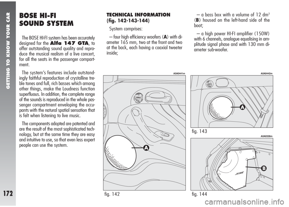
TECHNICAL INFORMATION
(fig. 142-143-144)
System comprises:
– four high efficiency woofers (A) with di-
ameter 165 mm, two at the front and two
at the back, each having a coaxial tweeter
inside;– a bass box with a volume of 12 dm
3
(B) housed on the left-hand side of the
boot;
– a high power HI-FI amplifier (150W)
with 6 channels, analogue equalising in am-
plitude signal phase and with 130 mm di-
ameter sub-woofer.
fig. 142
A0A0441m
Page 180 of 291
CORRECT USE OF THE CAR
178
SAFE DRIVING
In designing your Alfa 147 GTA, Al-
fa Romeo has worked thoroughly to achieve
a vehicle able to offer top levels of safety to
its passengers. However, the behaviour of
the driver is still a decisive factor for road
safety.
Below you will find a few simple rules for
travelling safely under different conditions.
You are certainly familiar with many of them
but it is still helpful to read them all care-
fully.
BEFORE DRIVING OFF
– Make sure the lights and headlights are
working properly.
– Adjust the seat, steering wheel and rear-
view mirrors, in order to obtain a correct po-
sition for driving.
– Carefully adjust the headrests so that
the head and not the neck rests on them.
Check that nothing (mats etc.) can get un-
der the foot pedals.– Make sure that any child restraint sys-
tems (seats, cradles, etc.) are correctly fas-
tened on the rear seat.
– Place any objects in the boot with care
to prevent abrupt braking from throwing
them forwards.
– Avoid heavy meals before a journey. A
light meal will help to keep reflexes ready.
Above all avoid alcohol.
Routinely remember to check:
– tyre pressure and conditions;
– engine oil level;
– engine coolant fluid level and system
conditions;
– brake fluid level;
– power steering oil level;
– windscreen washer fluid level.
WHEN TRAVELLING
– The first rule for safe driving is care.
– Care also means being able to predict
the actions of other road users.
– Strictly respect the traffic regulations in
all countries, especially the speed limits.
– Ensure that both yourself and your pas-
sengers are wearing their seat belts, that
children are carried with the appropriate
seats and that any animals are in appropri-
ate compartments.
– Long distances should be tackled in good
health.
Driving under the influence
of drugs and/or some
medicines is highly dangerous for
oneself and for others.
WARNING
Page 184 of 291
CORRECT USE OF THE CAR
182
Tyres
Check the pressure of the tyres routinely at
an interval of no more than 4 weeks: if the
pressure is too low consumption levels in-
crease as resistance to rolling is higher. It
should be underscored that in these condi-
tions tyre wear increases and vehicle per-
formance is lower, therefore also its safety.
Useless loads
Never travel with an overload in the boot.
The weight of the vehicle (especially in ur-
ban traffic), and its geometry heavily affect
consumption levels and stability.
Luggage/ski racks
Remove the luggage rack or ski rack from
the roof as soon as they are no longer used.
These accessories lower air penetration and
adversely affect consumption levels. When
needing to carry particularly voluminous ob-
jects, preferably use a trailer.Electric services
Use electric devices only for the amount of
time needed. Rearscreen heating, addition-
al headlights, windscreen wipers and heater
fan need a considerable amount of energy
therefore, increasing the requirement of cur-
rent increases fuel consumption (up to
+25% in the urban cycle).
Climate control system
The climate control system is a further load
bearing heavily on the engine inducing high-
er consumption levels (up to +20% on av-
erage). Outside temperature permitting,
preferably use the air vents.
Aerodynamic items
The use of non-certified aerodynamic items
may adversely affect air drag and con-
sumption levels.DRIVING STYLE
Starting
Do not warm the engine with the car at a
standstill or at idle or high speed: under
these conditions the engine warms up much
more slowly, increasing electrical consump-
tion and emissions. It is therefore advisable
to move off immediately, slowly, avoiding
high speeds. This way the engine will warm
faster.
Pointless manoeuvres
Avoid accelerating when waiting at traffic
lights or before switching off the engine. This
and also double declutching is absolutely
pointless on modern cars and also increase
consumption and pollution.
Gear shifting
As soon as the conditions of the traffic and
road allow, use a higher gear. Using a low
gear to obtain brilliant performance increases
consumption. In the same way improper use
of a high gear increases consumption, emis-
sions and engine wear.
Page 193 of 291
IN AN EMERGENCY
191
FIX&GO KIT FOR
QUICK TYRE
REPAIRING
The car is equipped with a tyre quick re-
pairing kit called FIX&GO.
fig. 11
A0A0374m
fig. 12
A0A0375m
fig. 13
A0A0376m
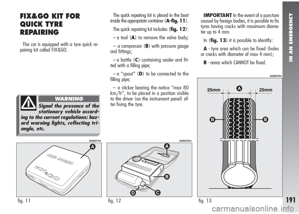
The quick repairing kit is placed in the boot
inside the appropriate container (A-fig. 11).
The quick repairing kit includes (fig. 12):
–a tool (A) to remove the valve body;
–a compressor (B) with pressure gauge
and fittings;
–a bottle (C) containing sealer and fit-
ted with a filling pipe;
–a “spout” (D) to be connected to the
filling pipe;
–a sticker bearing the notice “max 80
km/h”, to be placed in a position visible
to the driver (on the instrument panel) af-
ter fixing the tyre.IMPORTANTIn the event of a puncture
caused by foreign bodies, it is possible to fix
tyres having cracks with maximum diame-
ter up to 4 mm.
In (fig. 13) it is possible to identify:
A- tyre area which can be fixed (holes
or cracks with diameter of max 4 mm);
B- areas which CANNOT be fixed.
Signal the presence of the
stationary vehicle accord-
ing to the current regulations: haz-
ard warning lights, reflecting tri-
angle, etc.
WARNING
Page 199 of 291
IN AN EMERGENCY
197
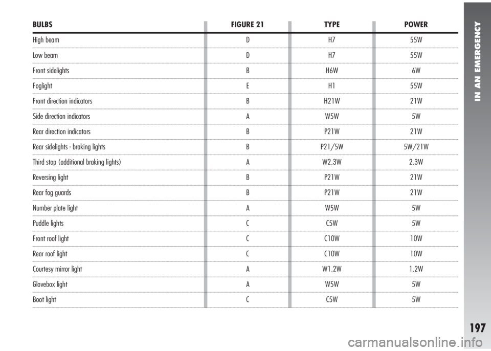
BULBS
High beam
Low beam
Front sidelights
Foglight
Front direction indicators
Side direction indicators
Rear direction indicators
Rear sidelights - braking lights
Third stop (additional braking lights)
Reversing light
Rear fog guards
Number plate light
Puddle lights
Front roof light
Rear roof light
Courtesy mirror light
Glovebox light
Boot lightFIGURE 21
D
D
B
E
B
A
B
B
A
B
B
A
C
C
C
A
A
CPOWER
55W
55W
6W
55W
21W
5W
21W
5W/21W
2.3W
21W
21W
5W
5W
10W
10W
1.2W
5W
5W TYPE
H7
H7
H6W
H1
H21W
W5W
P21W
P21/5W
W2.3W
P21W
P21W
W5W
C5W
C10W
C10W
W1.2W
W5W
C5W
Page 206 of 291
IN AN EMERGENCY
204
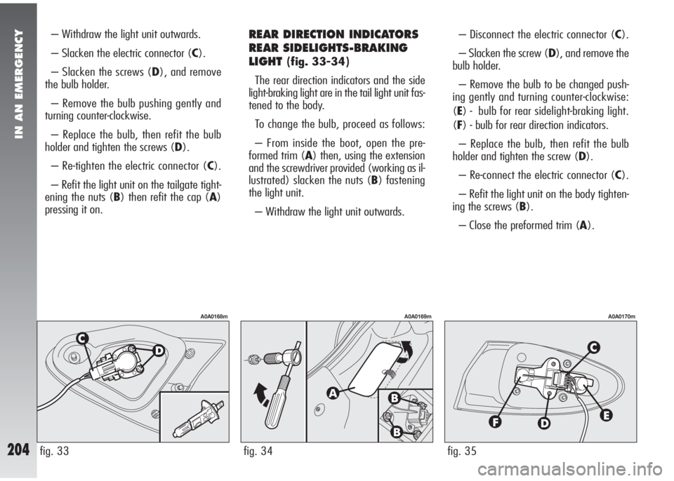
– Withdraw the light unit outwards.
– Slacken the electric connector (C).
– Slacken the screws (D), and remove
the bulb holder.
– Remove the bulb pushing gently and
turning counter-clockwise.
– Replace the bulb, then refit the bulb
holder and tighten the screws (D).
– Re-tighten the electric connector (C).
– Refit the light unit on the tailgate tight-
ening the nuts (B) then refit the cap (A)
pressing it on.REAR DIRECTION INDICATORS
REAR SIDELIGHTS-BRAKING
LIGHT
(fig. 33-34)
The rear direction indicators and the side
light-braking light are in the tail light unit fas-
tened to the body.
To change the bulb, proceed as follows:
– From inside the boot, open the pre-
formed trim (A) then, using the extension
and the screwdriver provided (working as il-
lustrated) slacken the nuts (B) fastening
the light unit.
– Withdraw the light unit outwards.– Disconnect the electric connector (C).
– Slacken the screw (D), and remove the
bulb holder.
– Remove the bulb to be changed push-
ing gently and turning counter-clockwise:
(E) - bulb for rear sidelight-braking light.
(F) - bulb for rear direction indicators.
– Replace the bulb, then refit the bulb
holder and tighten the screw (D).
– Re-connect the electric connector (C).
– Refit the light unit on the body tighten-
ing the screws (B).
– Close the preformed trim (A).
fig. 35
A0A0170m
fig. 34
A0A0169m
fig. 33
A0A0168m
Page 210 of 291
IN AN EMERGENCY
208
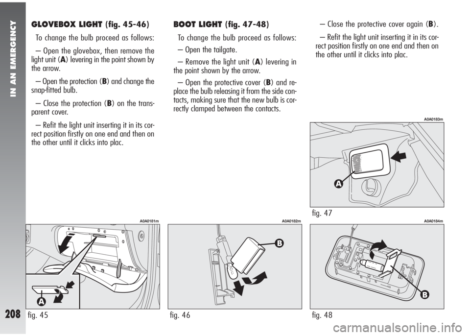
GLOVEBOX LIGHT (fig. 45-46)
To change the bulb proceed as follows:
– Open the glovebox, then remove the
light unit (A) levering in the point shown by
the arrow.
– Open the protection (B) and change the
snap-fitted bulb.
– Close the protection (B) on the trans-
parent cover.
– Refit the light unit inserting it in its cor-
rect position firstly on one end and then on
the other until it clicks into plac.BOOT LIGHT (fig. 47-48)
To change the bulb proceed as follows:
– Open the tailgate.
– Remove the light unit (A) levering in
the point shown by the arrow.
– Open the protective cover (B) and re-
place the bulb releasing it from the side con-
tacts, making sure that the new bulb is cor-
rectly clamped between the contacts.– Close the protective cover again (B).
– Refit the light unit inserting it in its cor-
rect position firstly on one end and then on
the other until it clicks into plac.
fig. 45
A0A0181m
fig. 46
A0A0182mfig. 47
A0A0183m
fig. 48
A0A0184m
Page 216 of 291
IN AN EMERGENCY
214
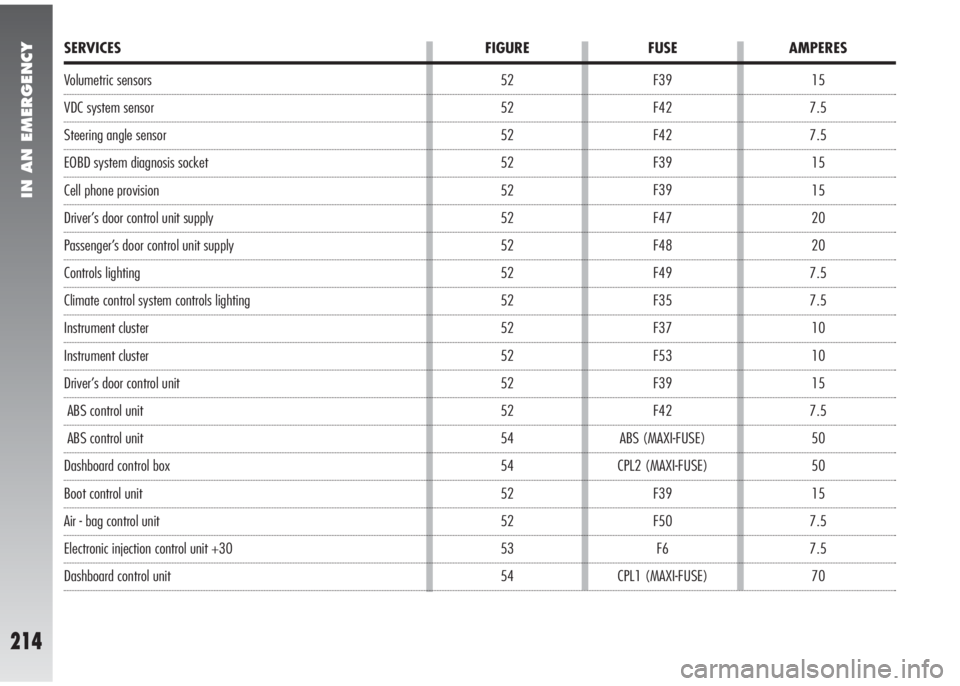
Volumetric sensors
VDC system sensor
Steering angle sensor
EOBD system diagnosis socket
Cell phone provision
Driver’s door control unit supply
Passenger’s door control unit supply
Controls lighting
Climate control system controls lighting
Instrument cluster
Instrument cluster
Driver’s door control unit
ABS control unit
ABS control unit
Dashboard control box
Boot control unit
Air - bag control unit
Electronic injection control unit +30
Dashboard control unit15
7.5
7.5
15
15
20
20
7.5
7.5
10
10
15
7.5
50
50
15
7.5
7.5
70 F39
F42
F42
F39
F39
F47
F48
F49
F35
F37
F53
F39
F42
ABS (MAXI-FUSE)
CPL2 (MAXI-FUSE)
F39
F50
F6
CPL1 (MAXI-FUSE) 52
52
52
52
52
52
52
52
52
52
52
52
52
54
54
52
52
53
54
SERVICES FIGURE FUSE AMPERES
Page 219 of 291
IN AN EMERGENCY
217
IF THE VEHICLE IS TO BE TOWED
The tow ring supplied with the vehicle is
housed in the tool box under the boot mat.
Front towing
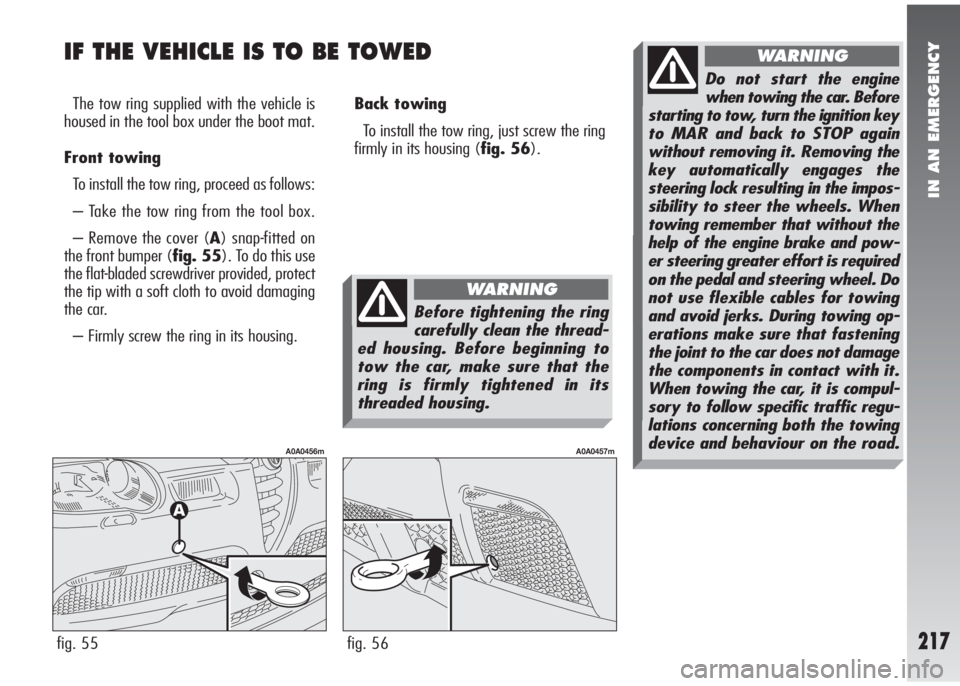
To install the tow ring, proceed as follows:
– Take the tow ring from the tool box.
– Remove the cover (A) snap-fitted on
the front bumper (fig. 55). To do this use
the flat-bladed screwdriver provided, protect
the tip with a soft cloth to avoid damaging
the car.
– Firmly screw the ring in its housing.Back towing
To install the tow ring, just screw the ring
firmly in its housing (fig. 56).
fig. 55
A0A0456m
fig. 56
A0A0457m
Before tightening the ring
carefully clean the thread-
ed housing. Before beginning to
tow the car, make sure that the
ring is firmly tightened in its
threaded housing.
WARNING
Do not start the engine
when towing the car. Before
starting to tow, turn the ignition key
to MAR and back to STOP again
without removing it. Removing the
key automatically engages the
steering lock resulting in the impos-
sibility to steer the wheels. When
towing remember that without the
help of the engine brake and pow-
er steering greater effort is required
on the pedal and steering wheel. Do
not use flexible cables for towing
and avoid jerks. During towing op-
erations make sure that fastening
the joint to the car does not damage
the components in contact with it.
When towing the car, it is compul-
sory to follow specific traffic regu-
lations concerning both the towing
device and behaviour on the road.
WARNING
Page 224 of 291
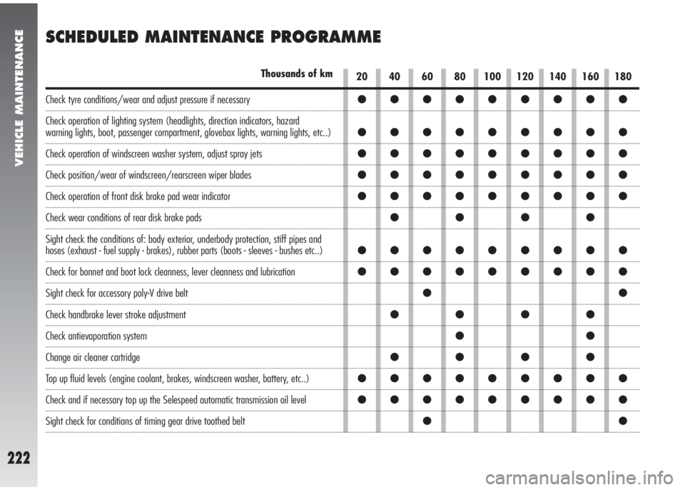
●●●●●●●●●
●●●●●●●●●
●●●●●●●●●
●●●●●●●●●
●●●●●●●●●
●●●●
●●●●●●●●●
●●●●●●●●●
●●
●●●●
●●
●●●●
●●●●●●●●●
●●●●●●●●●
●●
VEHICLE MAINTENANCE
222
SCHEDULED MAINTENANCE PROGRAMME
20 40 60 80 100 120 140 160 180Thousands of km
Check tyre conditions/wear and adjust pressure if necessary
Check operation of lighting system (headlights, direction indicators, hazard
warning lights, boot, passenger compartment, glovebox lights, warning lights, etc..)
Check operation of windscreen washer system, adjust spray jets
Check position/wear of windscreen/rearscreen wiper blades
Check operation of front disk brake pad wear indicator
Check wear conditions of rear disk brake pads
Sight check the conditions of: body exterior, underbody protection, stiff pipes and
hoses (exhaust - fuel supply - brakes), rubber parts (boots - sleeves - bushes etc..)
Check for bonnet and boot lock cleanness, lever cleanness and lubrication
Sight check for accessory poly-V drive belt
Check handbrake lever stroke adjustment
Check antievaporation system
Change air cleaner cartridge
Top up fluid levels (engine coolant, brakes, windscreen washer, battery, etc..)
Check and if necessary top up the Selespeed automatic transmission oil level
Sight check for conditions of timing gear drive toothed belt