light Alfa Romeo 147 2006 Owner handbook (in English)
[x] Cancel search | Manufacturer: ALFA ROMEO, Model Year: 2006, Model line: 147, Model: Alfa Romeo 147 2006Pages: 291, PDF Size: 5.52 MB
Page 204 of 291
IN AN EMERGENCY
202
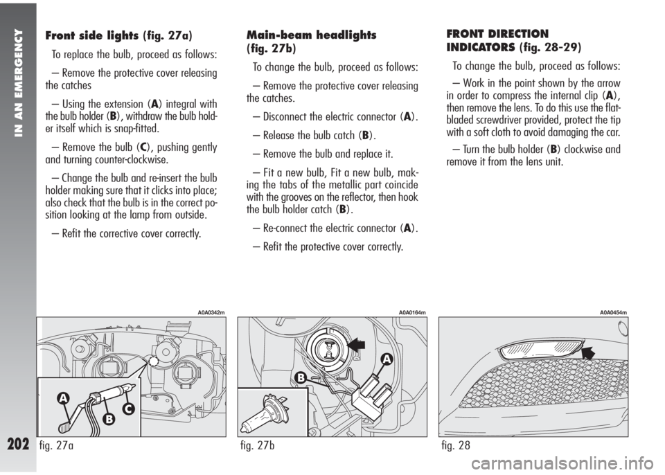
FRONT DIRECTION
INDICATORS
(fig. 28-29)
To change the bulb, proceed as follows:
– Work in the point shown by the arrow
in order to compress the internal clip (A),
then remove the lens. To do this use the flat-
bladed screwdriver provided, protect the tip
with a soft cloth to avoid damaging the car.
– Turn the bulb holder (B) clockwise and
remove it from the lens unit.
fig. 28
A0A0454m
Front side lights(fig. 27a)
To replace the bulb, proceed as follows:
– Remove the protective cover releasing
the catches
– Using the extension (A) integral with
the bulb holder (B), withdraw the bulb hold-
er itself which is snap-fitted.
– Remove the bulb (C), pushing gently
and turning counter-clockwise.
– Change the bulb and re-insert the bulb
holder making sure that it clicks into place;
also check that the bulb is in the correct po-
sition looking at the lamp from outside.
– Refit the corrective cover correctly.Main-beam headlights
(fig. 27b)
To change the bulb, proceed as follows:
– Remove the protective cover releasing
the catches.
– Disconnect the electric connector (A).
– Release the bulb catch (B).
– Remove the bulb and replace it.
– Fit a new bulb, Fit a new bulb, mak-
ing the tabs of the metallic part coincide
with the grooves on the reflector, then hook
the bulb holder catch (B).
– Re-connect the electric connector (A).
– Refit the protective cover correctly.
fig. 27b
A0A0164m
fig. 27a
A0A0342m
Page 205 of 291
IN AN EMERGENCY
203
– Remove the bulb pushing it gently and
turning it counter-clockwise.
– Replace the bulb.
– Refit the bulb holder turning clockwise
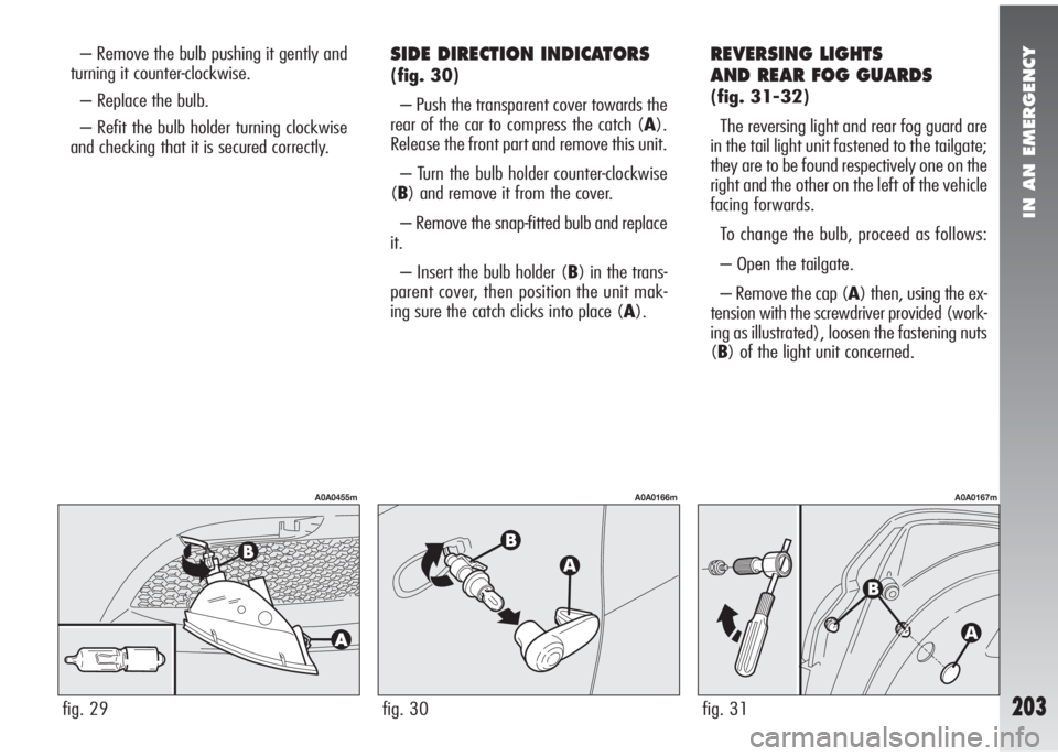
and checking that it is secured correctly.SIDE DIRECTION INDICATORS
(fig. 30)
– Push the transparent cover towards the
rear of the car to compress the catch (A).
Release the front part and remove this unit.
– Turn the bulb holder counter-clockwise
(B) and remove it from the cover.
– Remove the snap-fitted bulb and replace
it.
– Insert the bulb holder (B) in the trans-
parent cover, then position the unit mak-
ing sure the catch clicks into place (A).
REVERSING LIGHTS
AND REAR FOG GUARDS
(fig. 31-32)
The reversing light and rear fog guard are
in the tail light unit fastened to the tailgate;
they are to be found respectively one on the
right and the other on the left of the vehicle
facing forwards.
To change the bulb, proceed as follows:
– Open the tailgate.
– Remove the cap (A) then, using the ex-
tension with the screwdriver provided (work-
ing as illustrated), loosen the fastening nuts
(B) of the light unit concerned.
fig. 31
A0A0167m
fig. 29
A0A0455m
fig. 30
A0A0166m
Page 206 of 291
IN AN EMERGENCY
204
– Withdraw the light unit outwards.
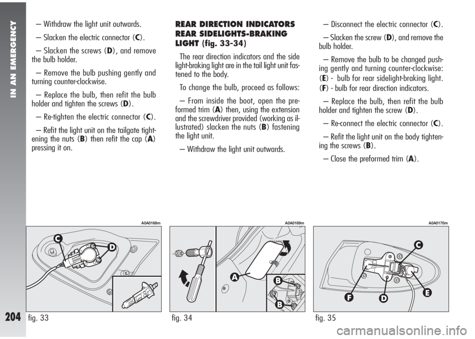
– Slacken the electric connector (C).
– Slacken the screws (D), and remove
the bulb holder.
– Remove the bulb pushing gently and
turning counter-clockwise.
– Replace the bulb, then refit the bulb
holder and tighten the screws (D).
– Re-tighten the electric connector (C).
– Refit the light unit on the tailgate tight-
ening the nuts (B) then refit the cap (A)
pressing it on.REAR DIRECTION INDICATORS
REAR SIDELIGHTS-BRAKING
LIGHT
(fig. 33-34)
The rear direction indicators and the side
light-braking light are in the tail light unit fas-
tened to the body.
To change the bulb, proceed as follows:
– From inside the boot, open the pre-
formed trim (A) then, using the extension
and the screwdriver provided (working as il-
lustrated) slacken the nuts (B) fastening
the light unit.
– Withdraw the light unit outwards.– Disconnect the electric connector (C).
– Slacken the screw (D), and remove the
bulb holder.
– Remove the bulb to be changed push-
ing gently and turning counter-clockwise:
(E) - bulb for rear sidelight-braking light.
(F) - bulb for rear direction indicators.
– Replace the bulb, then refit the bulb
holder and tighten the screw (D).
– Re-connect the electric connector (C).
– Refit the light unit on the body tighten-
ing the screws (B).
– Close the preformed trim (A).
fig. 35
A0A0170m
fig. 34
A0A0169m
fig. 33
A0A0168m
Page 207 of 291
IN AN EMERGENCY
205
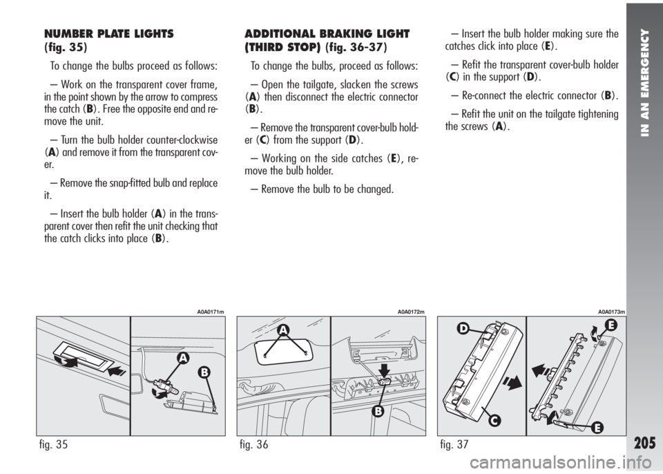
NUMBER PLATE LIGHTS
(fig. 35)
To change the bulbs proceed as follows:
– Work on the transparent cover frame,
in the point shown by the arrow to compress
the catch (B). Free the opposite end and re-
move the unit.
– Turn the bulb holder counter-clockwise
(A) and remove it from the transparent cov-
er.
– Remove the snap-fitted bulb and replace
it.
– Insert the bulb holder (A) in the trans-
parent cover then refit the unit checking that
the catch clicks into place (B).
ADDITIONAL BRAKING LIGHT
(THIRD STOP)
(fig. 36-37)
To change the bulbs, proceed as follows:
– Open the tailgate, slacken the screws
(A) then disconnect the electric connector
(B).
– Remove the transparent cover-bulb hold-
er (C) from the support (D).
– Working on the side catches (E), re-
move the bulb holder.
– Remove the bulb to be changed.– Insert the bulb holder making sure the
catches click into place (E).
– Refit the transparent cover-bulb holder
(C) in the support (D).
– Re-connect the electric connector (B).
– Refit the unit on the tailgate tightening
the screws (A).
fig. 37
A0A0173m
fig. 35
A0A0171m
fig. 36
A0A0172m
Page 208 of 291
IN AN EMERGENCY
206
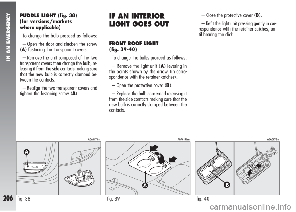
PUDDLE LIGHT (fig. 38)
(for versions/markets
where applicable)
To change the bulb proceed as follows:
– Open the door and slacken the screw
(A) fastening the transparent covers.
– Remove the unit composed of the two
transparent covers then change the bulb, re-
leasing it from the side contacts making sure
that the new bulb is correctly clamped be-
tween the contacts.
– Realign the two transparent covers and
tighten the fastening screw (A).IF AN INTERIOR
LIGHT GOES OUT
FRONT ROOF LIGHT
(fig. 39-40)
To change the bulbs proceed as follows:
– Remove the light unit (A) levering in
the points shown by the arrow (in corre-
spondence with the retainer catches).
– Open the protective cover (B).
– Replace the bulb concerned releasing it
from the side contacts making sure that the
new bulb is correctly clamped between the
contacts.– Close the protective cover (B).
– Refit the light unit pressing gently in cor-
respondence with the retainer catches, un-
til hearing the click.
fig. 40
A0A0176m
fig. 39
A0A0175m
fig. 38
A0A0174m
Page 209 of 291
IN AN EMERGENCY
207
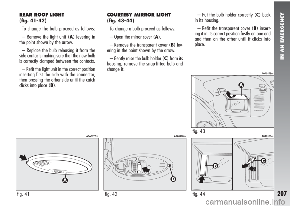
REAR ROOF LIGHT
(fig. 41-42)
To change the bulb proceed as follows:
– Remove the light unit (A) levering in
the point shown by the arrow.
– Replace the bulb releasing it from the
side contacts making sure that the new bulb
is correctly clamped between the contacts.
– Refit the light unit in the correct position
inserting first the side with the connector,
then pressing the other side until the catch
clicks into place (B).
COURTESY MIRROR LIGHT
(fig. 43-44)
To change a bulb proceed as follows:
– Open the mirror cover (A).
– Remove the transparent cover (B) lev-
ering in the point shown by the arrow.
– Gently raise the bulb holder (C) from its
housing, remove the snap-fitted bulb and
change it.– Put the bulb holder correctly (C) back
in its housing.
– Refit the transparent cover (B) insert-
ing it in its correct position firstly on one end
and then on the other until it clicks into
place.
fig. 41
A0A0177m
fig. 42
A0A0178mfig. 43
A0A0179m
fig. 44
A0A0180m
Page 210 of 291
IN AN EMERGENCY
208
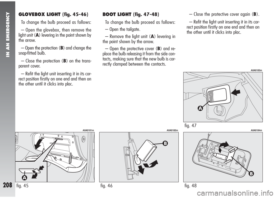
GLOVEBOX LIGHT (fig. 45-46)
To change the bulb proceed as follows:
– Open the glovebox, then remove the
light unit (A) levering in the point shown by
the arrow.
– Open the protection (B) and change the
snap-fitted bulb.
– Close the protection (B) on the trans-
parent cover.
– Refit the light unit inserting it in its cor-
rect position firstly on one end and then on
the other until it clicks into plac.BOOT LIGHT (fig. 47-48)
To change the bulb proceed as follows:
– Open the tailgate.
– Remove the light unit (A) levering in
the point shown by the arrow.
– Open the protective cover (B) and re-
place the bulb releasing it from the side con-
tacts, making sure that the new bulb is cor-
rectly clamped between the contacts.– Close the protective cover again (B).
– Refit the light unit inserting it in its cor-
rect position firstly on one end and then on
the other until it clicks into plac.
fig. 45
A0A0181m
fig. 46
A0A0182mfig. 47
A0A0183m
fig. 48
A0A0184m
Page 214 of 291
IN AN EMERGENCY
212
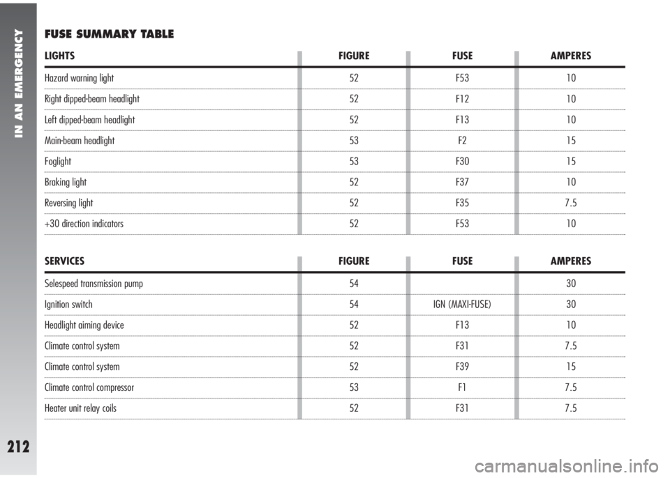
Hazard warning light
Right dipped-beam headlight
Left dipped-beam headlight
Main-beam headlight
Foglight
Braking light
Reversing light
+30 direction indicators10
10
10
15
15
10
7.5
10 F53
F12
F13
F2
F30
F37
F35
F53 52
52
52
53
53
52
52
52
LIGHTS FIGURE FUSE AMPERES
FUSE SUMMARY TABLE
30
30
10
7.5
15
7.5
7.5 IGN (MAXI-FUSE)
F13
F31
F39
F1
F31 54
54
52
52
52
53
52
SERVICES FIGURE FUSE AMPERES
Selespeed transmission pump
Ignition switch
Headlight aiming device
Climate control system
Climate control system
Climate control compressor
Heater unit relay coils
Page 215 of 291
IN AN EMERGENCY
213
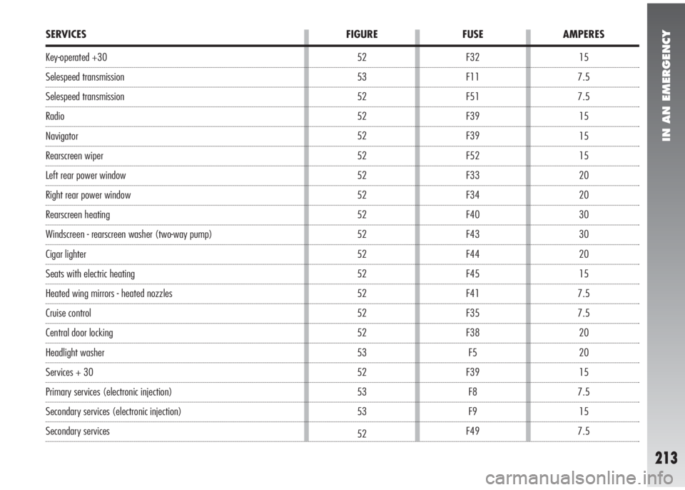
15
7.5
7.5
15
15
15
20
20
30
30
20
15
7.5
7.5
20
20
15
7.5
15
7.5 F32
F11
F51
F39
F39
F52
F33
F34
F40
F43
F44
F45
F41
F35
F38
F5
F39
F8
F9
F49 52
53
52
52
52
52
52
52
52
52
52
52
52
52
52
53
52
53
53
52
SERVICES FIGURE FUSE AMPERES
Key-operated +30
Selespeed transmission
Selespeed transmission
Radio
Navigator
Rearscreen wiper
Left rear power window
Right rear power window
Rearscreen heating
Windscreen - rearscreen washer (two-way pump)
Cigar lighter
Seats with electric heating
Heated wing mirrors - heated nozzles
Cruise control
Central door locking
Headlight washer
Services + 30
Primary services (electronic injection)
Secondary services (electronic injection)
Secondary services
Page 216 of 291
IN AN EMERGENCY
214
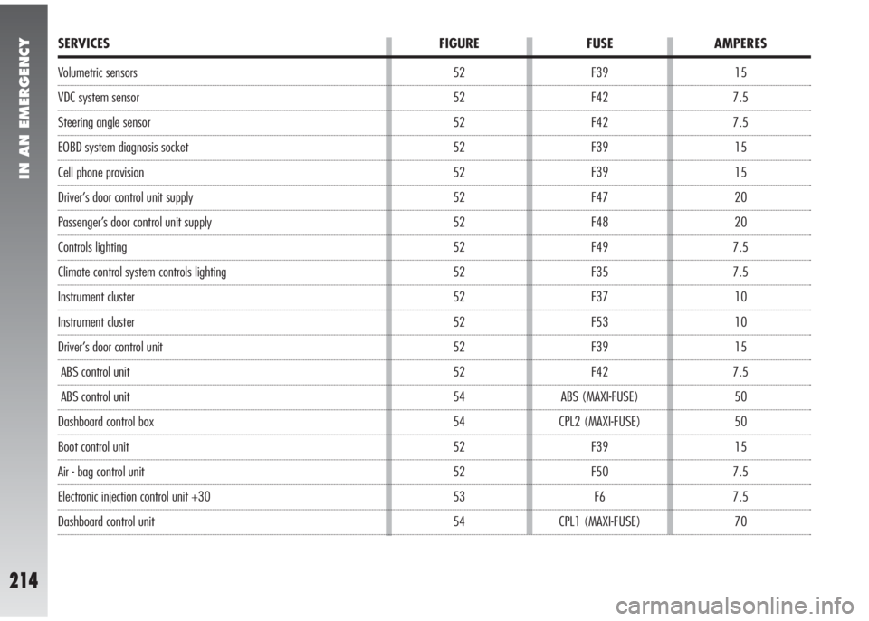
Volumetric sensors
VDC system sensor
Steering angle sensor
EOBD system diagnosis socket
Cell phone provision
Driver’s door control unit supply
Passenger’s door control unit supply
Controls lighting
Climate control system controls lighting
Instrument cluster
Instrument cluster
Driver’s door control unit
ABS control unit
ABS control unit
Dashboard control box
Boot control unit
Air - bag control unit
Electronic injection control unit +30
Dashboard control unit15
7.5
7.5
15
15
20
20
7.5
7.5
10
10
15
7.5
50
50
15
7.5
7.5
70 F39
F42
F42
F39
F39
F47
F48
F49
F35
F37
F53
F39
F42
ABS (MAXI-FUSE)
CPL2 (MAXI-FUSE)
F39
F50
F6
CPL1 (MAXI-FUSE) 52
52
52
52
52
52
52
52
52
52
52
52
52
54
54
52
52
53
54
SERVICES FIGURE FUSE AMPERES