technical specifications Alfa Romeo 147 2007 Owner handbook (in English)
[x] Cancel search | Manufacturer: ALFA ROMEO, Model Year: 2007, Model line: 147, Model: Alfa Romeo 147 2007Pages: 291, PDF Size: 5.52 MB
Page 7 of 291
5
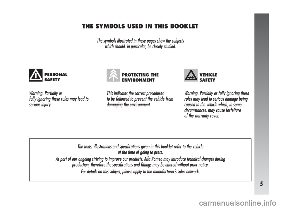
THE SYMBOLS USED IN THIS BOOKLET
The symbols illustrated in these pages show the subjects
which should, in particular, be closely studied.
This indicates the correct procedures
to be followed to prevent the vehicle from
damaging the environment. Warning. Partially or
fully ignoring these rules may lead to
serious injury.Warning. Partially or fully ignoring these
rules may lead to serious damage being
caused to the vehicle which, in some
circumstances, may cause forfeiture
of the warranty cover.
PERSONAL
SAFETYPROTECTING THE
ENVIRONMENTVEHICLE
SAFETY
The texts, illustrations and specifications given in this booklet refer to the vehicle
at the time of going to press.
As part of our ongoing striving to improve our products, Alfa Romeo may introduce technical changes during
production, therefore the specifications and fittings may be altered without prior notice.
For details on this subject, please apply to the manufacturer’s sales network.
Page 132 of 291
GETTING TO KNOW YOUR CAR
130fig. 132
A0A0437m
BONNET
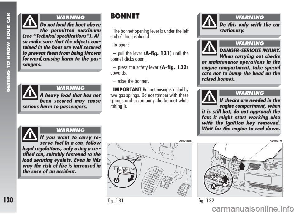
The bonnet opening lever is under the left
end of the dashboard.
To open:
– pull the lever (A-fig. 131) until the
bonnet clicks open.
– press the safety lever (A-fig. 132)
upwards.
– raise the bonnet.
IMPORTANTBonnet raising is aided by
two gas springs. Do not tamper with these
springs and accompany the bonnet while
raising it.
fig. 131
A0A0436m
A heavy load that has not
been secured may cause
serious harm to passengers.
WARNING
Do not load the boot above
the permitted maximum
(see “Technical specifications”). Al-
so make sure that the objects con-
tained in the boot are well secured
to prevent them from being thrown
forward,causing harm to the pas-
sangers.
WARNING
If you want to carry re-
serve fuel in a can, follow
legal regulations, only using a cer-
tified can, suitably fastened to the
load securing eyelets. Even in this
way the risk of fire is increased in
the case of an accident.
WARNING
Do this only with the car
stationary.
WARNING
DANGER-SERIOUS INJURY.
When carrying out checks
or maintenance operations in the
engine compartment, take special
care not to bump the head on the
raised bonnet.
WARNING
If checks are needed in the
engine compartment, when
it is still hot, do not approach the
fan: it might start working also
with the ignition key removed.
Wait for the engine to cool down.
WARNING
Page 133 of 291
GETTING TO KNOW YOUR CAR
131
To close:
– lower the bonnet until approx. 20 cm
from the engine compartment and then let
it drop, ensuring that it is fully closed and
not just held in position by the safety catch.
If the bonnet does not close properly do
not push it down but open it again and re-
peat the above procedure.
Scarves, ties and other loose
clothing might be pulled by
moving parts.
WARNING
For safety reasons the
bonnet shall always be
perfectly closed when travelling.
Always check for proper bonnet
locking. If the bonnet is left inad-
vertently open, stop the car im-
mediately and close the bonnet.
WARNING
ROOF RACK
PROVISION
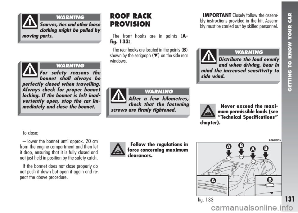
The front hooks are in points (A-
fig. 133).
The rear hooks are located in the points (B)
shown by the serigraph (
▼) on the side rear
windows.
Follow the regulations in
force concerning maximum
clearances.
IMPORTANTClosely follow the assem-
bly instructions provided in the kit. Assem-
bly must be carried out by skilled personnel.
Never exceed the maxi-
mum permissible loads (see
“Technical Specifications”
chapter).
fig. 133
A0A0232m
After a few kilometres,
check that the fastening
screws are firmly tightened.
WARNING
Distribute the load evenly
and when driving, bear in
mind the increased sensitivity to
side wind.
WARNING
Page 187 of 291
CORRECT USE OF THE CAR
185
IMPORTANTWhen winter tyres are
used with a maximum speed index below
the one that can be reached by the vehicle
(increased by 5%), place a notice in the pas-
senger compartment, plainly in the driver’s
view which states the maximum permissi-
ble speed of the winter tyres (as per CE Di-
rective).
Fit the same type of tyre on all four wheels
(brand and profile) to ensure higher driving
safety when braking and good handling.
Remember that it is inappropriate to
change the direction of rotation of tyres. WINTER TYRES
These tyres are specially designed for dri-
ving on snow and ice, to be fitted in re-
placement of those fitted on the car.
Use winter tyres of the same size as the
normal tyres provided on the car.
Alfa Romeo Authorised Services will be
pleased to advise you on the choice of the
car most suited to the use the Customer in-
tends to make of it.
For the type of tyre to be used, inflation
pressures and the specifications of winter
tyres, follow the instructions given in the
“Technical Specifications” chapter.
The winter features of these tyres are re-
duced considerably when the tread depth
is below 4 mm. In this case, they should be
replaced.
Due to the winter features, under normal
conditions of use or on long motorway jour-
neys, the performance of these tyres is low-
er than that of normal tyres.
It is necessary therefore to limit their use to
the purposes for which they are certified.
TRAILER TOWING
The car does not have the approval to tow
trailers.
Page 231 of 291
VEHICLE MAINTENANCE
229
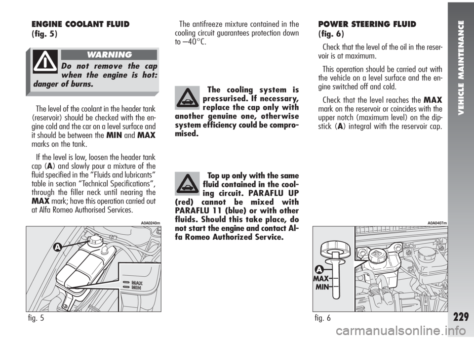
POWER STEERING FLUID
(fig. 6)
Check that the level of the oil in the reser-
voir is at maximum.
This operation should be carried out with
the vehicle on a level surface and the en-
gine switched off and cold.
Check that the level reaches the MAX
mark on the reservoir or coincides with the
upper notch (maximum level) on the dip-
stick (A) integral with the reservoir cap. The cooling system is
pressurised. If necessary,
replace the cap only with
another genuine one, otherwise
system efficiency could be compro-
mised.
Top up only with the same
fluid contained in the cool-
ing circuit. PARAFLU UP
(red) cannot be mixed with
PARAFLU 11 (blue) or with other
fluids. Should this take place, do
not start the engine and contact Al-
fa Romeo Authorized Service.
fig. 6
A0A0407m
ENGINE COOLANT FLUID
(fig. 5)
The level of the coolant in the header tank
(reservoir) should be checked with the en-
gine cold and the car on a level surface and
it should be between the MINandMAX
marks on the tank.
If the level is low, loosen the header tank
cap (A) and slowly pour a mixture of the
fluid specified in the ”Fluids and lubricants”
table in section “Technical Specifications”,
through the filler neck until nearing the
MAXmark; have this operation carried out
at Alfa Romeo Authorised Services.
fig. 5
A0A0240m
The antifreeze mixture contained in the
cooling circuit guarantees protection down
to –40°C.
Do not remove the cap
when the engine is hot:
danger of burns.
WARNING
Page 232 of 291
VEHICLE MAINTENANCE
230
If the oil level in the reservoir is below the
specified one, top up only with one of the
products listed in the “Fluids and lubricants”
table in the “Technical Specifications” chap-
ter proceeding as follows.
– Start the engine and wait for the oil lev-
el in the reservoir to stabilise.
– With the engine running, turn the steer-
ing wheel lock to lock a few times.
– Top up to the MAXlevel notch, then
refit the cap.
Oil consumption is very
low, if topping up again is
needed shortly afterwards,
have the system checked for pos-
sible leaks by Alfa Romeo Autho-
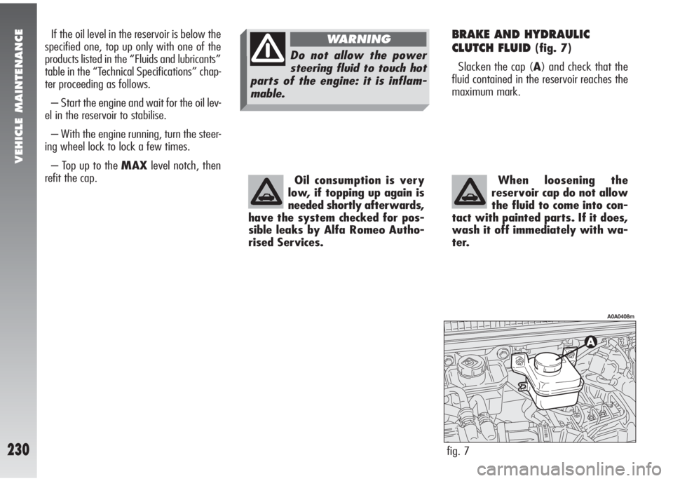
rised Services.BRAKE AND HYDRAULIC
CLUTCH FLUID
(fig. 7)
Slacken the cap (A) and check that the
fluid contained in the reservoir reaches the
maximum mark.
fig. 7
A0A0408m
When loosening the
reservoir cap do not allow
the fluid to come into con-
tact with painted parts. If it does,
wash it off immediately with wa-
ter.
Do not allow the power
steering fluid to touch hot
parts of the engine: it is inflam-
mable.
WARNING
Page 238 of 291
VEHICLE MAINTENANCE
236
– Do not check for current in the cables by
short-circuiting the ends.
– If electric welding is to be carried out on
the body, remember to disconnect the elec-
tronic control units, or remove them if the
work involves high temperatures.ELECTRONIC
CONTROL UNITS
With normal use of the vehicle. no partic-
ular precautions need to be taken.
In the event of work on the electric system
or emergency starting, the instructions giv-
en below must absolutely be adhered to:
– Always switch off the engine before dis-
connecting the battery from the electric sys-
tem.
– If it is necessary to charge the battery,
always disconnect it from the electric sys-
tem.
– When starting in an emergency, only
use an auxiliary battery and not a battery
charger.
– Check that the bias is correct and that
the connections between the battery and
the electric system are in efficient conditions.
– Before disconnecting or connecting the
terminals of electronic units, ensure that the
ignition key is not in the MARposition.
WHEELS AND TYRES
TYRE PRESSURE
Check the tyre pressure of every wheel, in-
cluding the spare.
The pressure should be checked with the
tyre rested and cold.
It is normal for the pressure to increase
when the car is in use. Should it become
necessary to restore the pressure with the
tyre hot, bear in mind that the pressure
should be +0.3 bar compared with the spec-
ified rating.
For the correct tyre inflation pressure, see
wheels in the “Technical Specifications”
chapter.
Alterations or repairs to
the electric system carried
out incorrectly and without taking
account of the specifications of the
system, may cause operating faults
with the risk of fire.
WARNING
Remember that vehicle
road holding also depends
on correct tyre inflation pressure.
WARNING
Page 245 of 291
TECHNICAL SPECIFICATIONS
243
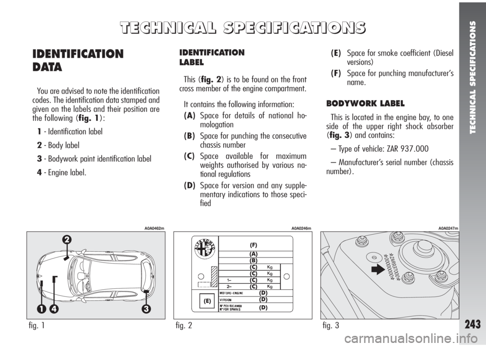
IDENTIFICATION
LABEL
This (fig. 2) is to be found on the front
cross member of the engine compartment.
It contains the following information:
(A)Space for details of national ho-
mologation
(B)Space for punching the consecutive
chassis number
(C)Space available for maximum
weights authorised by various na-
tional regulations
(D)Space for version and any supple-
mentary indications to those speci-
fied(E)Space for smoke coefficient (Diesel
versions)
(F)Space for punching manufacturer’s
name.
BODYWORK LABEL
This is located in the engine bay, to one
side of the upper right shock absorber
(fig. 3) and contains:
– Type of vehicle: ZAR 937.000
– Manufacturer’s serial number (chassis
number).
IDENTIFICATION
D ATA
You are advised to note the identification
codes. The identification data stamped and
given on the labels and their position are
the following (fig. 1):
1- Identification label
2- Body label
3- Bodywork paint identification label
4- Engine label.
T T
E E
C C
H H
N N
I I
C C
A A
L L
S S
P P
E E
C C
I I
F F
I I
C C
A A
T T
I I
O O
N N
S S
fig. 1
A0A0462m
fig. 2
A0A0246m
fig. 3
A0A0247m
Page 246 of 291
TECHNICAL SPECIFICATIONS
244
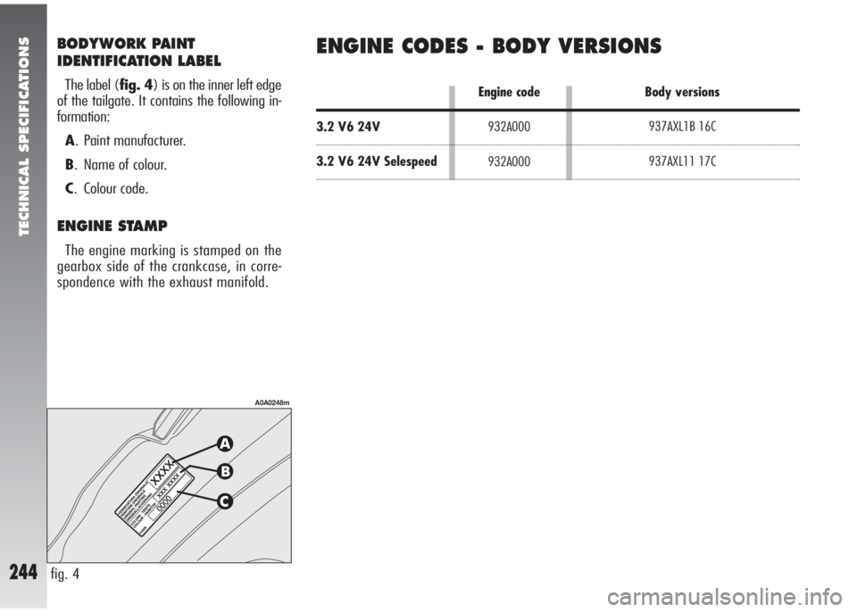
BODYWORK PAINT
IDENTIFICATION LABEL
The label (fig. 4) is on the inner left edge
of the tailgate. It contains the following in-
formation:
A. Paint manufacturer.
B. Name of colour.
C. Colour code.
ENGINE STAMP
The engine marking is stamped on the
gearbox side of the crankcase, in corre-
spondence with the exhaust manifold.
fig. 4
A0A0248m
ENGINE CODES - BODY VERSIONS
3.2 V6 24V
3.2 V6 24V Selespeed937AXL1B 16C
937AXL11 17C Engine code
932A000
932A000Body versions
Page 247 of 291
TECHNICAL SPECIFICATIONS
245
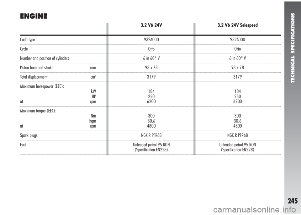
Code type
Cycle
Number and position of cylinders
Piston bore and stroke mm
Total displacement cm3
Maximum horsepower (EEC):
kW
HP
at rpm
Maximum torque (EEC):
Nm
kgm
at rpm
Spark plugs
Fuel
ENGINE
3.2 V6 24V
932A000
Otto
6 in 60° V
93 x 78
3179
184
250
6200
300
30.6
4800
NGK R PFR6B
Unleaded petrol 95 RON
(Specification EN228)
3.2 V6 24V Selespeed
932A000
Otto
6 in 60° V
93 x 78
3179
184
250
6200
300
30.6
4800
NGK R PFR6B
Unleaded petrol 95 RON
(Specification EN228)