Alfa Romeo 156 2006 Owner handbook (in English)
Manufacturer: ALFA ROMEO, Model Year: 2006, Model line: 156, Model: Alfa Romeo 156 2006Pages: 357, PDF Size: 5.04 MB
Page 181 of 357
GETTING TO KNOW YOUR CAR
179
If the
x
low brake fluid
warning light comes on (to-
gether with the message + symbol
shown by the display), stop the car
immediately and contact the near-
est Alfa Romeo Authorized Ser-
vices. Indeed, any leak of fluid
from the hydraulic system com-
promises the effectiveness of both
the conventional brake system and
the system with antilock system.
WARNING
The turning on of the
>
warning light (together
with the message + symbol shown
by the display) with the engine
running normally indicates an ABS
system fault. In this case the brak-
ing system preserves its effec-
tiveness, without however making
use of the antilock device. Under
these circumstances, the EBD sys-
tem may fail to give top perfor-
mance. In this case, too, you are
recommended to contact Alfa
Romeo Authorized Services imme-
diately, driving in such a way as to
avoid abrupt braking, to have the
system checked.
WARNING
VDC AND ASR
SYSTEMS(where required)VDC SYSTEM (VEHICLE
DYNAMICS CONTROL):
GENERALThe VDC is an electronic vehicle stability
control system which, acting on the torque
and braking the wheels in a differentiated
manner, helps to bring the car back to the
correct course in the event of loss of grip.
While travelling the car is subjected to lat-
eral and longitudinal forces that may be
controlled by the driver up to when the
tyres offer adequate road-holding; when
this falls below the minimum level, the car
starts to deviate from the course required
by the driver.
Above all on rough surfaces (such as cob-
bles, or due to the presence of water, ice
or soil), changes in speed (when accelerat-
ing or braking) and/or course (bends or the
need to avoid obstacles) can cause the tyres
to lose grip.When the sensors detect the conditions
that would lead to skidding, the VDC system
acts on the engine and brakes generating
a stabilising torque.
The system performance
levels, in terms of active
safety, should not induce the dri-
ver to run pointless and unjustified
risks. Driving conduct should al-
ways be suited to the conditions of
the road surface, vision and traf-
fic. The responsibility for road
safety is always and anyway the
vehicle driver’s concern.
The VDC system helps the driver
to keep control of the car in the
event of loss of tyre grip.
The forces induced by the VDC sys-
tem to control the lack of stability
of the car always and anyway de-
pend on the grip between the tyre
and the road surface.
WARNING
Page 182 of 357

GETTING TO KNOW YOUR CAR
180
The heart of the VDC system is the VDC
control unit which with the data supplied by
the sensors installed on the car, calculates
the centrifugal forces generated when the
car is cornering. The yawing sensor detects
the rotations of the car around its own ver-
tical axis. The centrifugal forces generated
when the car is cornering are detected by
a highly sensitive lateral acceleration sensor.
The stabilising action of the VDC system is
based on calculations made by the
system’s electronic control unit which
processes the signals received from the
steering wheel rotation, lateral acceleration
and individual wheel rotation sensors. These
signals allow the control unit to recognise
the manoeuvre the driver intends to do
when turning the steering wheel.
The control unit processes the information
received from the sensors and is therefore
capable of detecting the position of the car
and comparing it with the trajectory the dri-
ver would like to follow instant by instant.
In the event of a discrepancy, the control
unit chooses and commands the most suit-
able action to bring the car back to the re-
quired course within a fraction of a second:
braking one or more wheels at a different
braking force and, if necessary it reduces the
power transmitted by the engine. The corrective actions are changed and con-
trolled continuously until the car returns to
the required course.
The action of the VDC system considerably
increases the active safety of the vehicle un-
der many critical situations and it is partic-
ularly useful also when the road surface grip
conditions change.
For the VDC, ASR and ABS
systems to work correctly,
the tyres must be of the same
brand and type on all wheels, in
perfect conditions and above all of
the specified type, brand and size.
WARNING
During use of the compact
spare wheel, the VDC sys-
tem continues working. It should be
borne in mind that the spare wheel
is smaller than a normal tyre,
therefore its grip is lower than that
of the other tyres of the car.
WARNING
VDC SYSTEM OPERATIONThe VDC system turns on automatically
when the car is started and cannot be
switched off. It is however possible to cut
off operation of the ASR system pressing the
corresponding button on the centre console.
The main components of the VDC system
are:
– an electronic control unit which
processes the signals received from the var-
ious sensors and brings about the most ap-
propriate strategy;
– a sensor that detects the position of the
steering wheel;
– four sensors that detect the rotation
speed of each wheel;
– a sensor that detects rotation of the car
around the vertical axis;
– a sensor that detects lateral acceleration
(centrifugal force).
Page 183 of 357
GETTING TO KNOW YOUR CAR
181
ASR FUNCTION (ANTISLIP
REGULATION): GENERALThe ASR system integrates the VDC sys-
tem controlling the vehicle drive and com-
ing into operation automatically each time
one or both driving wheels skid.
Two different control systems are activated,
depending on the skidding conditions:
– If skidding concerns both driving wheels,
because it is caused by the excessive power
transmitted, the ASR system cuts in reduc-
ing the power transmitted by the engine.
– If skidding concerns only one driving
wheel, the ASR system cuts in automatically
braking the skidding wheel, with an effect
similar to that of a self-locking differential.The action of the ASR system is particularly
helpful under the following conditions:
– Skidding of the inner wheel on a bend,
due to the effect of the dynamic changes of
the load or over-accelerating.
– Excessive power transmitted to the
wheels, also in relation to the conditions of
the road surface.
– Acceleration on slippery, snowy or icy
surfaces.
– In the case of loss of grip on a wet sur-
face (aquaplaning).
CUTTING IN OF THE VDC
SYSTEMThe cutting in of the VDC system is indi-
cated by the flashing of the warning lightá
on the instrument cluster, to inform the
driver that the car is in critical conditions of
stability and grip.
TURNING ON THE ASR
FUNCTIONThe ASR function turns on automatically
each time the engine is started.
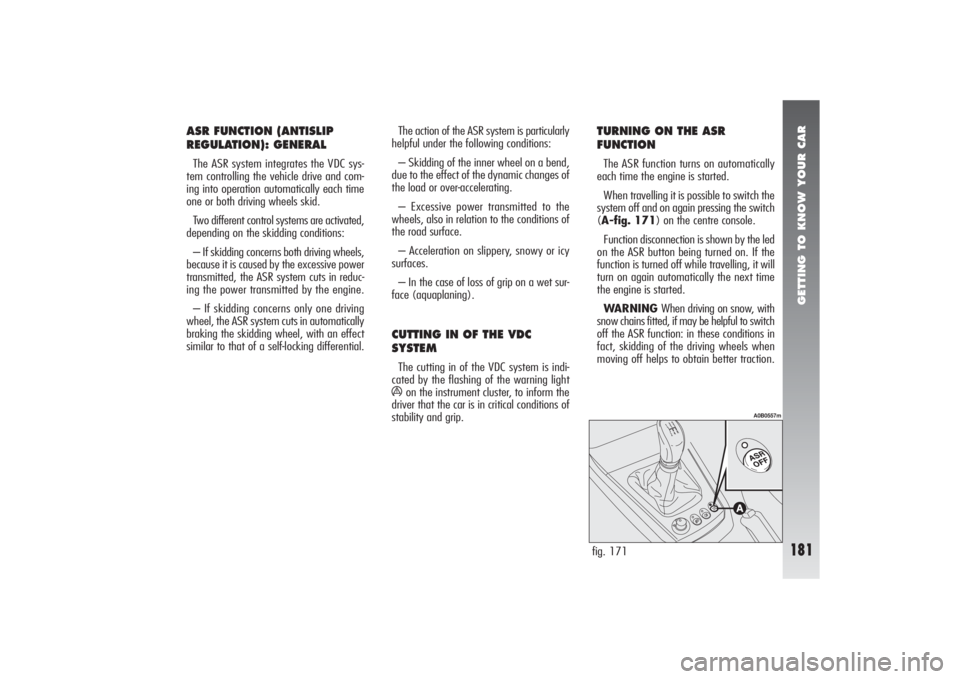
When travelling it is possible to switch the
system off and on again pressing the switch
(A-fig. 171
) on the centre console.
Function disconnection is shown by the led
on the ASR button being turned on. If the
function is turned off while travelling, it will
turn on again automatically the next time
the engine is started.
WARNING When driving on snow, with
snow chains fitted, if may be helpful to switch
off the ASR function: in these conditions in
fact, skidding of the driving wheels when
moving off helps to obtain better traction.
fig. 171
A0B0557m
Page 184 of 357
GETTING TO KNOW YOUR CAR
182
EOBD SYSTEMThe EOBD (European On Board Diagnosis)
system fitted in the car conforms with the
98/69/EC (EURO 3) Directive and the
2001/1/EC Directive, level B (EURO4) for
2.0 JTS, 2.0 JTS Selespeed and JTD 20V
Multijet versions.
This system continuously monitors the
components of the vehicle related to emis-
sions; it also indicates, when the warning
light
U
comes on on the instrument panel
(together with the message + symbol
shown by the display) that the components
in question are in poor conditions.
The objective is the following:
– to keep under control the efficiency of
the system;
– to indicate when a malfunction causes
an increase in the emissions beyond the
threshold established by European regula-
tions;
– to indicate the need to replace the de-
teriorated components.
The system also has a diagnostic connec-
tor, which can be interfaced with adequate in-
struments, that enables the error codes stored
in the control unit to be read, together with
a series of specific parameters concerning the
operation and diagnosis of the engine.This check can also be made by the traf-
fic control agents.
If, when the ignition key
is turned to MAR, the
U
warning light does not
come on or if, when driving, it
lights up and emits a fixed light or
a flashing one (together with the
message + symbol shown by the
display), contact an Alfa Romeo
Authorized Service Station as soon
as possible. The operation of the
U
warning light can also be
checked by means of special equip-
ment available to the traffic con-
trol officers. Comply with the reg-
ulations in force in country where
you drive your car.
WARNINGAfter the problem has beel
resolved, to completely check the system,
the Alfa Romeo Authorized Services must
carry out tests on a test bench and, if nec-
essary, road tests that could be long.
WARNING LIGHT ON
INSTRUMENT PANELWhen the ignition key is turned to MAR,
the dial warning light
á
comes on but must
go out after a few seconds.
If the warning light does not go out, or if it
stays on (together with the message + sym-
bol on the display and the coming on of the
ASR button led) when the vehicle is running,
contact Alfa Romeo Authorized Services.
The flashing of the warning lamp when the
vehicle is running indicates the actuation of
the VDC system.
VDC system failure warning
In the event of a failure the VDC system
disengages automatically and the
á
warn-
ing light on the instrument cluster turns on
glowing steadily (together with the message
+ symbol shown on the display and the com-
ing on of the ASR button led).
In the event of a VDC system failure the
car behaves like a vehicle not fitted with this
system: in any case it is advisable to con-
tact Alfa Romeo Authorized Services as soon
as possible.
Page 185 of 357
GETTING TO KNOW YOUR CAR
183
SOUND SYSTEM(where applicable)
The fixed sound system, with cassette
player (radio with cassette player) or CD
player with parametric sound equalizer (ra-
dio with CD player) has been designed to
suit the specific characteristics of the pas-
senger compartment, with a personalised
design that matches the style of the dash-
board. The sound system instructions for use
are described in the attached supplement.
SOUND SYSTEM
PRESETTING SYSTEM(for versions/markets where
applicable)
The car, if not delivered with sound sys-
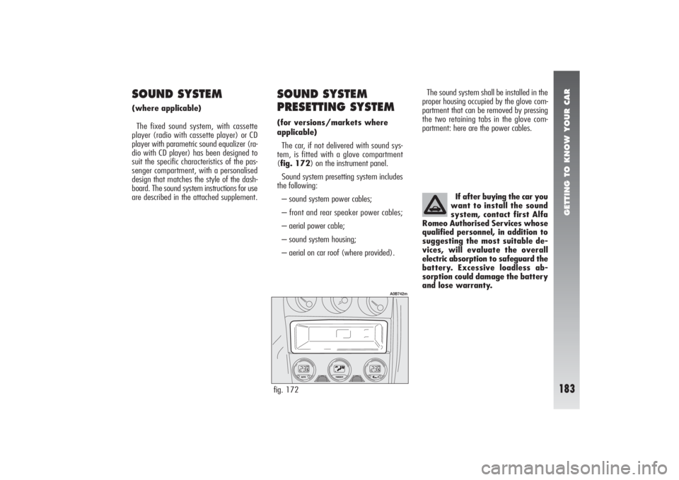
tem, is fitted with a glove compartment
(fig. 172) on the instrument panel.
Sound system presetting system includes
the following:
– sound system power cables;
– front and rear speaker power cables;
– aerial power cable;
– sound system housing;
– aerial on car roof (where provided).The sound system shall be installed in the
proper housing occupied by the glove com-
partment that can be removed by pressing
the two retaining tabs in the glove com-
partment: here are the power cables.
If after buying the car you
want to install the sound
system, contact first Alfa
Romeo Authorised Services whose
qualified personnel, in addition to
suggesting the most suitable de-
vices, will evaluate the overall
electric absorption to safeguard the
battery. Excessive loadless ab-
sorption could damage the battery
and lose warranty.fig. 172
A0B742m
Page 186 of 357
GETTING TO KNOW YOUR CAR
184
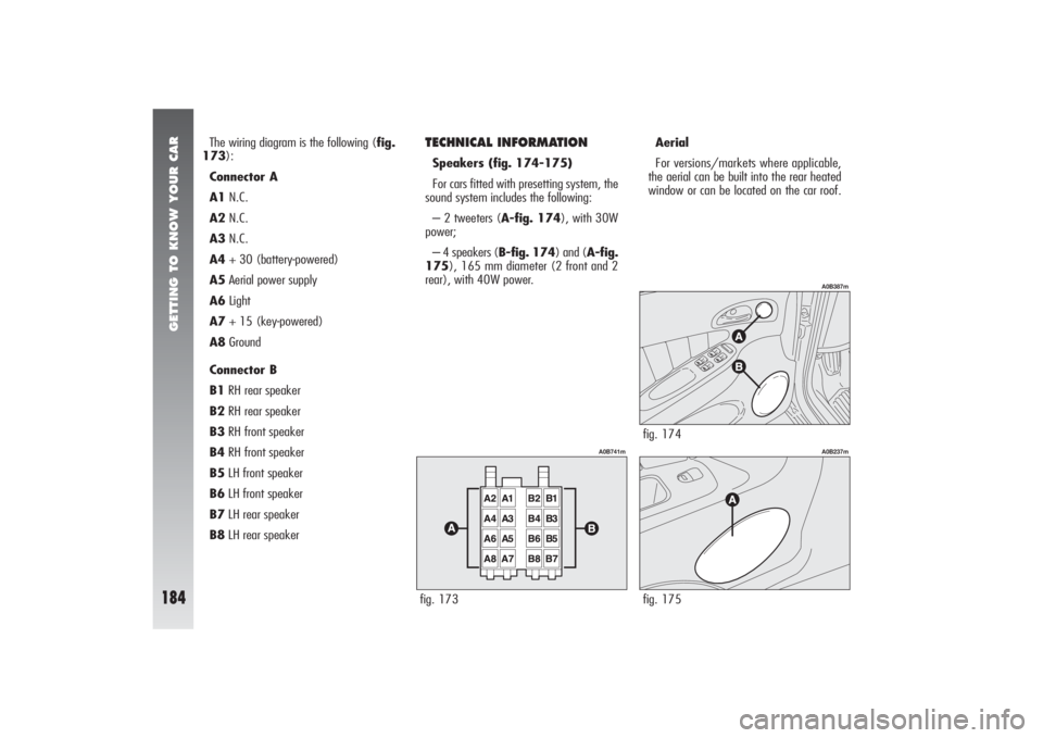
The wiring diagram is the following (fig.
173):
Connector A
A1N.C.
A2N.C.
A3N.C.
A4+ 30 (battery-powered)
A5Aerial power supply
A6Light
A7+ 15 (key-powered)
A8Ground
Connector B
B1RH rear speaker
B2RH rear speaker
B3RH front speaker
B4RH front speaker
B5LH front speaker
B6LH front speaker
B7LH rear speaker
B8LH rear speaker
TECHNICAL INFORMATIONSpeakers (fig. 174-175)
For cars fitted with presetting system, the
sound system includes the following:
– 2 tweeters (A-fig. 174), with 30W
power;
– 4 speakers (B-fig. 174) and (A-fig.
175), 165 mm diameter (2 front and 2
rear), with 40W power.Aerial
For versions/markets where applicable,
the aerial can be built into the rear heated
window or can be located on the car roof.fig. 173
A0B741m
fig. 174
A0B387m
fig. 175
A0B237m
Page 187 of 357
GETTING TO KNOW YOUR CAR
185
REFUELLING PETROL ENGINESIn order to prevent the vehicle being filled
with leaded petrol, the diameter of the filler
neck is smaller than the nozzle used on
pumps delivering leaded petrol.At low temperatures, the degree of fluid-
ity of fuel oil may become insufficient due
to the formation of paraffins leading to dan-
ger of clogging the fuel oil filter.
Therefore, to avoid inconveniences, sum-
mer and winter fuel oils are normally dis-
tributed depending on the season.
However, during the intermediate season,
characterised by a large difference between
outside temperatures (0°C to 15°C), the
quality of the fuel oil distributed to the
pumps may not be adequate.
In this case, and above all if the use of the
car involves stopping and then starting again
at low temperatures (e.g. mountains),
make sure the car is filled with winter fuel
oil; if not, you are advised to mix the fuel
oil with a DIESEL MIXadditive in the pro-
portions stated on the can, pouring first the
antifreeze and then the fuel oil into the tank.
TheDIESEL MIXantifreeze should be
mixed with the fuel oil before reactions due
to cold take place. Adding it too late will
prove pointless. The anti-pollution devices
present on the vehicle im-
pose the use of four-star
unleaded fuel with an octane num-
ber (R.O.N.) above 95.
Under no circumstances
should conventional leaded
petrol be used, as this
would irreparably damage the cat-
alyst. If the tank is accidentally
filled with leaded fuel, even in
minute quantities, DO NOT START
THE ENGINE. Do not attempt to di-
lute the petrol with lead free fuel.
Drain the entire fuel circuit and
tank.
If the catalyst is not
working properly, harmful
emissions reach the ex-
haust, resulting in environment pol-
lution.The car must be refuelled
only with fuel oil for motor
vehicles, in conformity with
European specification EN590. The
use of other products or mixtures
may damage the engine irrepara-
bly, resulting in invalidation of the
warranty for the damage caused.
If the tank is accidentally filled
with another type of fuel, do not
start the engine but drain the tank.
If the engine has been run even for
a brief period, the tank must be
drained together with the entire
fuel circuit.
JTD ENGINES
Page 188 of 357

GETTING TO KNOW YOUR CAR
186
FUEL CAP
(fig. 176)
The fuel flap is released from inside the
car, raising the front part of the lever (A).
The fuel cap (A-fig. 177) has a catch
to prevent misplacing it (B) that fastens it
to the flap (C).
WARNINGThe fuel tank is sealed her-
metically and pressure may build up inside.
Any noise of rushing air when the cap is re-
moved is perfectly normal.
fig. 176
A0B0044m
fig. 177
A0B0045m
In case of need, replace
the fuel cap only with an
original one; otherwise,
the efficiency of the petrol vapour
recovery system could be badly af-
fected.
EMERGENCY FLAP OPENING
DEVICEIf the lever (A-fig. 176) fails to work,
it is still possible to open the flap by pulling
the cord (A-fig. 178) on the right-hand
side of the luggage compartment.fig. 178
A0B0388m
WARNINGFor your safety, make sure
that the fuelling pump nozzle is inserted cor-
rectly into the housing, before starting the
engine.
Do not get near the fuel
filler with naked flames or
lit cigarettes: danger of fire. Also
avoid going too near the filler with
the face to avoid inhaling harmful
vapours.
WARNING
Page 189 of 357

GETTING TO KNOW YOUR CAR
187
ENVIRONMENTAL
PROTECTIONThe design and construction of the vehi-
cle have not only been developed with the
traditional aspects of performance and
safety in mind, but also take into account
the increasingly pressing problems tied to
protecting the environment.
The choice of materials, techniques and
particular parts are the result of work which
has made it possible to drastically reduce
the harmful effects on the environment and
guarantee respect for the severest interna-
tional norms.USE OF NON-TOXIC
MATERIALSNone of the components of the vehicle con-
tains asbestos. The padding and the climate
control system do not contain CFCs which
are held to be responsible for the depletion
of the ozone layer.
The colouring agents and the corrosion in-
hibitors used on the nuts, screws and bolts
do not contain cadmium any more, which
could pollute the atmosphere or water tables.
PARKING SENSORS
(WHERE PROVIDED)(optional for versions/markets
where applicable)
The parking system detects and informs
the driver (through an intermittent acoustic
signal) about the presence of obstacles in
the rear part of the car (fig. 179). ACTIVATIONThe sensors are automatically activated
when the reverse gear is engaged.
The sound produced by the acoustic alarm
becomes continuous when the distance be-
tween the car and the obstacle is less that
30 cm.
ACOUSTIC SIGNALWhen the reverse gear is engaged an in-
termittent acoustic signal is automatically
activated.
The acoustic signal:
– raises with the reduction of distance be-
tween the car and the obstacle;
– becomes continuous when the distance
between the car and the obstacle is less that
30 cm and stops if the distance raises.
– is constant if the distance is unvaried.
If this situation takes place for side sensors,
the signal is stopped after about 3 seconds
to prevent sound indications when per-
forming manoeuvres near walls.fig. 179
A0B0609m
Page 190 of 357

GETTING TO KNOW YOUR CAR
188
EMISSION REDUCING DEVICES
(petrol engines)Trivalent catalytic converter
(catalytic silencer)
The exhaust system is fitted with a cat-
alyzer formed of alloys of noble metals. It
is housed in a stainless steel container which
is able to resist the high operating temper-
atures.
The catalyzer converts the unburnt hydro-
carbons, carbon monoxide and nitrogen ox-
ides present in the exhaust gas (even if in
small quantities thanks to the electronic in-
jection and ignition system) into harmless
compounds.Lambda probe
A sensor (lambda probe) measures the
content of oxygen present in the exhaust
gas. The signal transmitted by the lambda
probe is use by the injection and ignition
electronic control unit to adjust the air-fuel
mixture.
Anti-evaporation system
As it is impossible, even when the engine
is switched off, to prevent the formation of
fuel vapours, a system has been devised
which imprisons the vapours in a special ac-
tivated carbon container.
During operation of the engine, these
vapours are sucked up and sent to com-
bustion.
EMISSION REDUCING DEVICES
(JTD engines )Oxidising catalytic converter
Converts the polluting substances present
in the exhaust gases (carbon monoxide, un-
burned hydrocarbons and particulate) into
harmless substances, thus reducing the
fumes and smell that are typical of diesel
engines.
The catalytic converter consists of a stain-
less steel case that houses a ceramic hon-
eycomb body coated with noble metal used
as a catalyst.
Exhaust gas recirculation system
(E.G.R.)
This system recycles, i.e. re-uses, a vary-
ing percentage of the exhaust gases, de-
pending on engine operating conditions.
It is used, when necessary, to control ni-
tric oxides.
Due to the high tempera-
tures reached during oper-
ation of the catalytic converter, the
vehicle should not be parked over
inflammable materials (paper, fuel
oils, grass, dry leaves, etc.).
WARNING