ESP Alfa Romeo 159 2006 Owner handbook (in English)
[x] Cancel search | Manufacturer: ALFA ROMEO, Model Year: 2006, Model line: 159, Model: Alfa Romeo 159 2006Pages: 299, PDF Size: 4.64 MB
Page 69 of 299
67
SAFETY
DEVICES
WARNING
LIGHTS AND
MESSAGES
IN AN
EMERGENCY
CAR
MAINTENANCE
TECHNICAL
SPECIFICATIONS
INDEX
CORRECT USE
OF THE CAR
DASHBOARD
AND
CONTROLS
N˙Splitting of the air flow between
Oall vents.
Rear seat Three-zone
configuration controls
Pressing buttons
N/O(rear controls)
you can manually choose one of the 3
possible modes for air distribution to the
rear side of passenger's compartment
NAir flow to the vents on the central
console (passengers’ body).
OAir flow towards the rear lower part
of the passenger compartment. This
type of distribution allows heating of the
passenger compartment in the shortest
time by proper setting of the tempera-
ture.
NSplitting of the air flow between
Othe vents to the lower part of the
passenger compartment (warmest air)
and the rear vents (coolest air).
To restore automatic air distribution con-
trol after a manual selection, press but-
tons AUTO (front controls) or AUTO (rear
controls).
AIR RECIRCULATION AND
AQS FUNCTION (AIR
QUALITY SYSTEM)
ON/OFF (where provided)
Inside air recirculation is controlled ac-
cording to the following operating log-
ics:
❒automatic control, indicated by but-
ton led “A”;
❒forced switching on (inside air recir-
culation always on), indicated by the
turning on of the circular led around
the button;
❒forced switching off (air recirculation
always off with air inlet from the out-
side), indicated by the turning off of
the circular led around the button.
With A.Q.S. (air quality sensor - where
provided), the operating logics becomes
sequential by pressing button
v.IMPORTANTThe inside air recircula-
tion system makes it possible to reach
the required heating or cooling condi-
tions faster. It is however inadvisable to
use it on rainy/cold days as it would
considerably increase the possibility of
the windows misting inside, especially
if the climate control compressor is off.
It is advisable to turn on the inside air
recirculation system in queues or tunnels
to avoid admitting polluted air from out-
side. The prolonged use of this function
should however be avoided, especially
with several persons on board, to avoid
the possibility of the windows misting
inside and to guarantee the required
fresh air inlet.
Page 79 of 299
77
SAFETY
DEVICES
WARNING
LIGHTS AND
MESSAGES
IN AN
EMERGENCY
CAR
MAINTENANCE
TECHNICAL
SPECIFICATIONS
INDEX
CORRECT USE
OF THE CAR
DASHBOARD
AND
CONTROLS
❒pressing the brake pedal, pressing the
clutch pedal (in these cases the last
stored speed will stay memorised, to
resume it press button RES);
❒pressing the accelerator pedal; in this
case the system is disengaged only
temporarily; device operation will be
resumed automatically when releas-
ing the pedal;
❒with car speed below the preset lim-
it (in these cases the last stored
speed will stay memorised, to resume
it press button RES);
Automatic Cruise Control
deactivation
The Cruise Control is temporarily deac-
tivated when the ABS or VDC systems
come into operation (above a max. pre-
set time): in this case the last set speed
will stay memorised, to recall it press
buttonRES.
In the event of Cruise Control or engine
control system failure, the device is de-
activated until removing the electronic
key from the ignition device. In this
event contact Alfa Romeo Authorized
Services.
❒engage the gear selected at the time
of speed memorising (4th or 5th
gear);
❒press the RESbutton (set at stalk
end).
TO INCREASE THE
MEMORISED SPEED
The speed memorised can be increased
in two ways:
❒pressing the accelerator and then
memorising the new speed reached;
or
❒moving the stalk upwards (+).
Each operation of the stalk will corre-
spond to a slight increase in speed
(about 1.5 km/h), while keeping the
stalk upwards will correspond to a con-
tinuous speed increase.
TO REDUCE MEMORISED
SPEED
The speed memorised can be increased
in two ways:
❒disengaging the device and then
memorising the new speed;
or
❒moving the stalk downwards (–) un-
til reaching the new speed which will
be memorised automatically.
Each operation of the stalk will corre-
spond to a slight decrease in speed
(about 1.5 km/h), while keeping the
stalk downwards will correspond to a
continuous speed decrease.
DEVICE DISENGAGEMENT
The device is disengaged in one of the
following cases:
❒turning the knurled ring A-fig. 57
toO;
❒turning the engine off or removing
the electronic key from the ignition
device;
Page 102 of 299

100
SAFETY
DEVICES
WARNING
LIGHTS AND
MESSAGES
IN AN
EMERGENCY
CAR
MAINTENANCE
TECHNICAL
SPECIFICATIONS
INDEX
CORRECT USE
OF THE CAR
DASHBOARD
AND
CONTROLS
C(where provided) – rear left window
opening/closing; “automatic continu-
ous” mode operation during window
opening/closing;
D(where provided) – rear right win-
dow opening/closing; “automatic con-
tinuous” mode operation just during win-
dow opening;
E(where provided) – rear power win-
dow enabling/disabling controls (when
rear power window controls are dis-
abled, the led on button Ewill turn on
and disabled controls will turn off).
Press buttons A,B,CorDto open/
close the required window.
Pressing briefly one of the buttons the
window “jerks” whereas a prolonged
pressing makes the window opening or
closing in “automatic continuous”
mode.
Pressing button A,B,CorDagain will
stop the window in the required posi-
tion.Front passenger door/
rear doors
Front passenger door and, on certain
versions, rear doors are fitted with but-
ton panels controlling opening/closing
of the corresponding window.
CONTROLS
Driver side
On the driver’s door panel are set the
buttonsfig. 93 for controlling, with
electronic key fitted into the ignition de-
vice:
A– front left window opening/closing;
window opening or closing in “auto-
matic continuous” mode;
B– front right window opening/clos-
ing; window opening or closing in “au-
tomatic continuous” mode (only ver-
sions with 4 power windows);
A0E0051mfig. 93
Improper use of the
power windows can be
dangerous. Before and
during its operation ensure that
any passengers are not at risk
from the moving glass either by
personal objects getting caught
in the mechanism or by being in-
jured by it directly. Always re-
move the ignition key when
getting out of the car to prevent
the power windows being op-
erated accidentally and consti-
tuting a danger to the passen-
gers in the car.
Page 109 of 299
107
SAFETY
DEVICES
WARNING
LIGHTS AND
MESSAGES
IN AN
EMERGENCY
CAR
MAINTENANCE
TECHNICAL
SPECIFICATIONS
INDEX
CORRECT USE
OF THE CAR
DASHBOARD
AND
CONTROLS
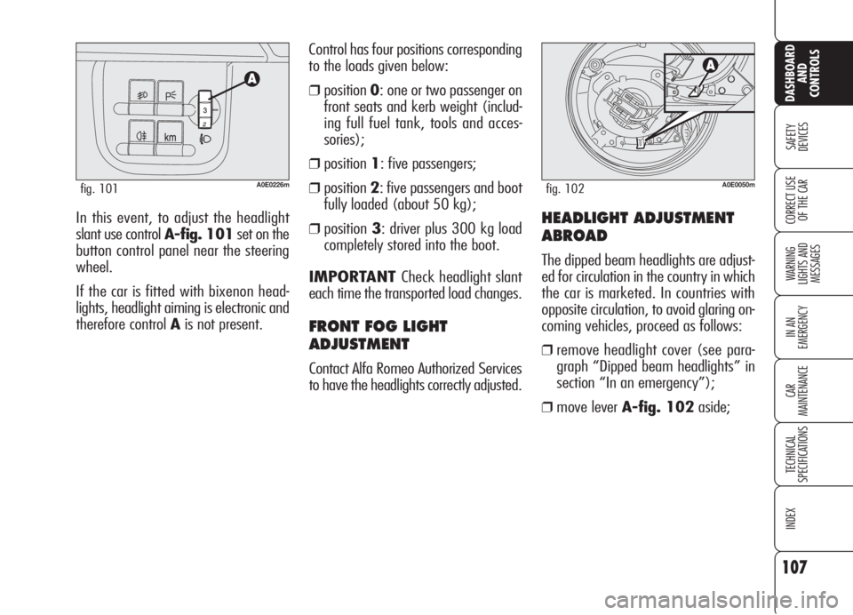
In this event, to adjust the headlight
slant use control A-fig. 101set on the
button control panel near the steering
wheel.
If the car is fitted with bixenon head-
lights, headlight aiming is electronic and
therefore control Ais not present.Control has four positions corresponding
to the loads given below:
❒position0: one or two passenger on
front seats and kerb weight (includ-
ing full fuel tank, tools and acces-
sories);
❒position1: five passengers;
❒position2: five passengers and boot
fully loaded (about 50 kg);
❒position3: driver plus 300 kg load
completely stored into the boot.
IMPORTANT Check headlight slant
each time the transported load changes.
FRONT FOG LIGHT
ADJUSTMENT
Contact Alfa Romeo Authorized Services
to have the headlights correctly adjusted.
A0E0226mfig. 101
HEADLIGHT ADJUSTMENT
ABROAD
The dipped beam headlights are adjust-
ed for circulation in the country in which
the car is marketed. In countries with
opposite circulation, to avoid glaring on-
coming vehicles, proceed as follows:
❒remove headlight cover (see para-
graph “Dipped beam headlights” in
section “In an emergency”);
❒move lever A-fig. 102aside;
A0E0050mfig. 102
Page 113 of 299

111
SAFETY
DEVICES
WARNING
LIGHTS AND
MESSAGES
IN AN
EMERGENCY
CAR
MAINTENANCE
TECHNICAL
SPECIFICATIONS
INDEX
CORRECT USE
OF THE CAR
DASHBOARD
AND
CONTROLS
Performance of the
VDC system, in terms
of active safety should not in-
duce the driver to take point-
less and unnecessary risks.
The style of driving must in
any case always be adapted to
the conditions of the road sur-
face, visibility an traffic. Road
safety is always the driver’s
responsibility.
WARNING
During the use of the
space-saver spare
wheel (where provided), the
VDC system carries on work-
ing. However, you must re-
mind that the space-saver
spare wheel has dimensions
smaller than the standard tyre
and therefore its grip is re-
duced as to the other car tyres.
WARNING
For correct operation of
the VDC system, the
tyres must absolutely be of
the same brand and type on all
wheels, in perfect conditions
and, above all, of type, brand
and size specified.
WARNING
HILL HOLDER SYSTEM
(where provided)
This system is an integral part of the VDC
system and it is provided to facilitate
starting on slopes:
❒uphill: car at a standstill on a road
with a gradient higher than 6%, en-
gine running, clutch and brake ped-
al depressed, gearbox to neutral or
engaged gear other than reverse;
❒downhill: car at a standstill on a road
with a gradient higher than 6%, en-
gine running, clutch and brake ped-
al depressed and reverse gear en-
gaged.
At pickup the VDC system control unit
will keep brake force on wheels until
reaching the torque suitable for starting,
or in any case for about 1 second in or-
der to pass easily from the brake pedal
to the accelerator pedal.
Page 121 of 299

119
SAFETY
DEVICES
WARNING
LIGHTS AND
MESSAGES
IN AN
EMERGENCY
CAR
MAINTENANCE
TECHNICAL
SPECIFICATIONS
INDEX
CORRECT USE
OF THE CAR
DASHBOARD
AND
CONTROLS
The acoustic alarm will stop immediately
as distance raises. The acoustic alarm is
constant if the distance measured by
central sensors is unvaried, whereas if
this situation takes place for side sen-
sors the acoustic alarm is muted after
about 3 seconds to prevent sound indi-
cations when performing manoeuvres
near walls.
SENSORS
Obstacles are detected by 4 sensors lo-
cated in the front bumper (where pro-
vided)fig. 105and 4 sensors located
in the rear bumperfig. 106.
Parking manoeuvres
however are always
under the driver’s responsibil-
ity that shall always check the
absence of people (specially
children) or animals in the ma-
noeuvre space. This system is
just a help for the driver but
she/he shall never reduce at-
tention during dangerous ma-
noeuvres even if performed at
low speed.
WARNING
A0E0231mfig. 105
A0E0232mfig. 106
BUZZER
The presence of any obstacle and its dis-
tance from the car is indicated by the
buzzers installed inside the passenger
compartment:
❒on versions with 4 rear sensors, the
rear buzzer will indicate the presence
of rear obstacles;
❒on versions with 8 sensors (4 front
sensors and 4 rear sensors) obstacles
are indicated by rear and front
buzzers. This feature gives the dri-
ver the direction (front/rear) of the
obstacle.
Page 123 of 299

121
SAFETY
DEVICES
WARNING
LIGHTS AND
MESSAGES
IN AN
EMERGENCY
CAR
MAINTENANCE
TECHNICAL
SPECIFICATIONS
INDEX
CORRECT USE
OF THE CAR
DASHBOARD
AND
CONTROLS
If a failure is indicated, stop the car, turn
the engine off and then clean the sen-
sors. Make sure to be far from possible
ultrasound sources (e.g.: truck pneu-
matic brakes or pneumatic hammers).
If failure cause has been eliminated the
system will resume regular operation
and warning
tand the corresponding
warning message will turn off.
If the warning light stays on, contact Al-
fa Romeo Authorized Services to have
the system inspected, although the sys-
tem keeps on working. If the failure de-
tected does not impair system operation,
the system keeps on working and fail-
ure is stored in order to be then detect-
ed by Alfa Romeo Authorized Services
at next inspection.
GENERAL WARNINGS
When parking, take the utmost care to
obstacles that may be set above or un-
der the sensors. Objects set close to the
car front or rear part, under certain cir-
cumstances are not detected and could
therefore cause damages to the car or
be damaged.
Indications sent by the sensors can be
altered by dirt, snow or ice deposited on
the sensors or by ultrasound systems
(e.g.: truck pneumatic brakes or pneu-
matic hammers) set nearby the car.
TOWING TRAILERS
Rear sensors are reactivated automati-
cally when removing the trailer cable
plug.
FAILURE INDICATIONS
The system control unit checks every
system component each time the key is
fitted into the ignition device. Sensors
and relevant electrical connections are
then constantly monitored during sys-
tem operation.
Sensor failure is indicated by turning on
of warning light
t(where provided)
on the instrument panel (on certain ver-
sions together with the message on the
display) (see section “Warning lights
and messages”).
Rear sensors operation
is deactivated automat-
ically when the trailer
electric cable plug is fitted into
the car tow hook socket.
Page 156 of 299

154
SAFETY
DEVICES
WARNING
LIGHTS AND
MESSAGES
IN AN
EMERGENCY
CAR
MAINTENANCE
TECHNICAL
SPECIFICATIONS
INDEX
DASHBOARD
AND
CONTROLS
CORRECT USE
OF THE CAR
IMPORTANTAfter a taxing drive, you
should allow the engine to “catch its
breath” before turning it off by letting it
idle to allow the temperature in the en-
gine compartment to fall.
IMPORTANTTurning the car off will
deactivate the electronic safety systems
and turn off the external lights.IMPORTANTIn the event of engine
locking while the car is running, due to
safety reasons it will not be possible to
take the electronic key out of the igni-
tion device. To remove it, turn the in-
strument panel on and off by pressing
buttonSTART/STOPwith brake ped-
al (and clutch pedal) released and car
stopped.
REMOVING THE ELECTRONIC
KEY FROM THE IGNITION
DEVICE IN AN EMERGENCY
In the event of a failure at engine switch-
ing off system or at electronic key un-
locking system proceed as follows:
❒press the unlocking button to remove
the metal insert (see paragraph
“Electronic key” in section “Dash-
board and controls”);
STOPPING THE ENGINE
With car stopped press button START/
STOP. When the engine is off it will be
possible to remove the electronic key
from the ignition device.
A quick burst on the ac-
celerator before turning
off the engine serves
absolutely no practical purpose,
it wastes fuel and is damaging
especially to turbocharged en-
gines.❒fit the metal insert B-fig. 1of the
electronic key into the slot A;
❒remove the electronic key from the
ignition device.
IMPORTANTOnly fit the metal insert
Bof the electronic key into slot A-fig.1.
IMPORTANTStop the car before
emergency removal of the key, since re-
moving the key with the engine running
will turn both the engine and the in-
strument panel off and the steering lock
will not be engaged.
A0E0043mfig. 1In an emergency, and
for safety reasons the
engine can be turned off when
the car is running by pressing
repeatedly (3 times within
2 seconds) or by keeping
pressed button START/STOP
for a few seconds. In this case
the steering lock cannot be en-
gaged.
WARNING
Page 159 of 299
157
SAFETY
DEVICES
WARNING
LIGHTS AND
MESSAGES
IN AN
EMERGENCY
CAR
MAINTENANCE
TECHNICAL
SPECIFICATIONS
INDEX
DASHBOARD
AND
CONTROLS
CORRECT USE
OF THE CAR
Climate control
The air conditioner is an additional load
which greatly affects the engine leading
to higher consumption. When the tem-
perature outside the car permits it, use
the air vents where possible.
Spoilers
The use of aerodynamic optional extras
which are not certified for the specific
use on the vehicle, may reduce the aero-
dynamic penetration of the vehicle and
increase consumption. Unnecessary loads
Do not travel with too much luggage
stowed in the boot. The weight of the
car (especially when driving in town)
and its trim greatly affects consumption
and stability.
Roof rack/ski rack
Remove the roof rack or the ski rack
from the roof as soon as they are no
longer used. These accessories lower air
penetration and adversely affect con-
sumption levels. When needing to car-
ry particularly voluminous objects, prefer-
ably use a trailer.
Electric devices
Use electric devices only for the amount
of time needed. Rear heated window,
additional headlights, windscreen wipers
and heater fan need a considerable
amount of energy, therefore increasing
the requirement of current increases fu-
el consumption (up to +25% in the ur-
ban cycle).CONTAINING
RUNNING COSTS
Here are some suggestions which may
help you to keep the running costs of
your car down and lower the amount of
toxic emissions released into the at-
mosphere.
GENERAL CONSIDERATIONS
Car maintenance
Have checks and adjustments carried out
in accordance with the “Service sched-
ule”.
Tyres
Check the pressure of the tyres routine-
ly at an interval of no more than 4
weeks: if the pressure is too low, con-
sumption levels increase as resistance
to rolling is higher.
Page 185 of 299
183
SAFETY
DEVICES
WARNING
LIGHTS AND
MESSAGES
CAR
MAINTENANCE
TECHNICAL
SPECIFICATIONS
INDEX
CORRECT USE
OF THE CAR
DASHBOARD
AND
CONTROLS
IN AN
EMERGENCY
IF A TYRE
IS PUNCTURED
For versions/markets where applicable,
the car can be equipped with the “Quick
tyre repair kit Fix&Go automatic“. Op-
erations required to change a wheel are
described in the following chapter.
As an alternative to the kit “Fix & Go
automatic”, the car can be provided (up-
on request) with space-saver spare
wheel or standard size spare wheel;
wheel changing and correct use of the
jack and space-saver spare wheel call for
some precautions as listed below.
BUMP STARTING
Never bump start the engine (by push-
ing, towing, or coasting downhill) as this
could cause fuel to flow into the catalytic
exhaust system and damage it beyond
repair.
Remember that the
brake booster and the
power steering system are not
operating until the engine is
started, a greater effort will
therefore be required to press
the brake pedal or turn the
steering wheel.
WARNING
Alert other drivers that
the car is stationary in
compliance with local regula-
tions: hazard warning lights,
warning triangle etc. Any pas-
sengers on board should leave
the car, especially if it is heav-
ily laden. Passengers should
stay away from oncoming
traffic while the wheel is be-
ing changed on. If the wheel is
being changed on a steep or
badly surfaced road, place the
wedges or other suitable ma-
terial under the wheel to stop
the car. Never start the engine
when the car is jacked up. If
you were towing a trailer, un-
couple the trailer before jack-
ing the car.
WARNING