cap Alfa Romeo 159 2006 Owner handbook (in English)
[x] Cancel search | Manufacturer: ALFA ROMEO, Model Year: 2006, Model line: 159, Model: Alfa Romeo 159 2006Pages: 299, PDF Size: 4.64 MB
Page 186 of 299

184
SAFETY
DEVICES
WARNING
LIGHTS AND
MESSAGES
CAR
MAINTENANCE
TECHNICAL
SPECIFICATIONS
INDEX
CORRECT USE
OF THE CAR
DASHBOARD
AND
CONTROLS
IN AN
EMERGENCY
The space-saver spare
wheel (for versions/
markets where applicable) is
specific to your car; do not use
it on other models, or use the
spare wheel of other models
on your car. The space-saver
spare wheel shall only be used
in an emergency. It shall only
be used for the distance nec-
essary to reach a service point
and the car speed shall not ex-
ceed 80 Km/h. The spare
wheel has a sticker that sum-
marises the main cautions for
use and limitations. The stick-
er should never be removed or
covered!. Never fit a wheel
cap on a space-saver spare
wheel.
WARNING
When driving with a
space-saver spare
wheel fitted, the driving per-
formance of the car changes.
Avoid accelerating or braking
sharply, abrupt turns or fast
cornerings. The life of the
spare wheel is approx. 3000
Km, after this distance it
should be replaced with an-
other of the same type. Nev-
er attempt to fit a conven-
tional tyre on a rim designed
for use as a space-saver spare
wheel. Have the punctured
wheel repaired and refitted as
soon as possible. Two or more
space-saver spare wheels
should never be used togeth-
er. Do not grease the threads
of bolts before installing them:
they might slip out.
WARNING
The jack shall only be
used for changing
wheels on the car with which
it is provided or on cars of the
same model. It must not be used
for other purposes such as for
instance raising cars of other
models. In no case should it be
used for repairs under the car.
Incorrect positioning of the jack
may cause the jacked car to fall.
Do not use the jack for higher
capacities than stated on its la-
bel. Snow chains cannot be fit-
ted to the space-saver spare
wheel. So, if a front (drive)
wheel is punctured and chains
are needed, a rear wheel should
be fitted to the front of the car
and the spare wheel should be
fitted to the rear. This way with
two normal drive wheels, snow
chains can be fitted to them to
solve an emergency.
WARNING
Page 188 of 299

186
SAFETY
DEVICES
WARNING
LIGHTS AND
MESSAGES
CAR
MAINTENANCE
TECHNICAL
SPECIFICATIONS
INDEX
CORRECT USE
OF THE CAR
DASHBOARD
AND
CONTROLS
IN AN
EMERGENCY
❒Loosen the bolts of the wheel to be
replaced by about one turn with the
wrench provided A-fig. 5; if the car
is fitted with alloy rims, shake the car
to facilitate removing this rim from
the wheel hub;❒Remove the wheel cap A-fig. 6
(only versions with steel rims);❒Take out the tool container fig. 4;
A0E0134mfig. 4A0E0206mfig. 5A0E0207mfig. 6
Page 191 of 299

189
SAFETY
DEVICES
WARNING
LIGHTS AND
MESSAGES
CAR
MAINTENANCE
TECHNICAL
SPECIFICATIONS
INDEX
CORRECT USE
OF THE CAR
DASHBOARD
AND
CONTROLS
IN AN
EMERGENCY
REFITTING A
NORMAL WHEEL
Following the procedure described pre-
viously, raise the car and remove the
spare wheel.
Versions with steel rims
Proceed as follows:
❒Make sure the contact surfaces be-
tween standard wheel and hub are
clean so that the fastening bolts will not
come loose;
❒Fit the standard wheel taking into ac-
count that pin B-fig. 10shall coin-
cide with one of the holes A;
❒Place the wheel cap on the wheel rim
making symbol
C, (marked inside the
wheel cap), coincide with the inflation
valvefig. 12;
❒Using the wrench provided, tighten the
fastening bolts;
❒ Lower the car and remove the jack;
❒Using the wrench provided, fully tight-
en the bolts in the sequence shown
infig. 11;
A0E0211mfig. 13
Versions with alloy rims
Proceed as follows:
❒tighten pin A-fig. 13in one of the
holes of the wheel hub fastening
bolts;
❒insert the wheel on the pin and, us-
ing the wrench provided, tighten the
four bolts available;
❒loosen pin A-fig. 13and tighten
the last fastening bolt;
❒lower the car and remove the jack,
then, using the wrench provided tight-
en the bolts according to the sequence
previously shown for the space-saver
spare wheel fig. 11.When you have finished:
❒Stow the spare wheel in the space
provided in the boot;
❒Fit the jack partially open in its con-
tainer forcing it lightly to prevent it
from vibrating when travelling;
❒Put the tools back into their places in
the container;
❒Arrange the container complete with
tools on the space-saver spare wheel;
❒Reposition properly the boot stiff cov-
ering.
A0E0236mfig. 12
Page 194 of 299

192
SAFETY
DEVICES
WARNING
LIGHTS AND
MESSAGES
CAR
MAINTENANCE
TECHNICAL
SPECIFICATIONS
INDEX
CORRECT USE
OF THE CAR
DASHBOARD
AND
CONTROLS
IN AN
EMERGENCY
Proceed as follows:
❒set the wheel to be repaired with
valveA-fig. 16in the position
shown in the figure, then pull up
the handbrake, take the quick
tyre repair kit and put it on the
ground near the wheel to be repaired;
❒loosen tyre inflation valve cap, take
out the filler hose A-fig. 17and
screw the ring nut B-fig. 18on the
tyre valve;
A0E0116mfig. 17
A0E0214mfig. 18
INFLATING PROCEDURE
A0E0212mfig. 16
Put on the protection
gloves provided to-
gether with quick tyre repair
kit.
WARNING
The compressor shall
not be operated for
more than 20 minutes. Risk of
overheating!. Tyres repaired
with the quick tyre repair kit
shall be used temporarily only.
WARNING
Replace the cylinder if
sealer has run out. Do
not throw away the
cylinder and the sealing fluid.
Have the sealing fluid and the
cylinder disposed of in compli-
ance with national and local reg-
ulations.
Page 201 of 299

199
SAFETY
DEVICES
WARNING
LIGHTS AND
MESSAGES
CAR
MAINTENANCE
TECHNICAL
SPECIFICATIONS
INDEX
CORRECT USE
OF THE CAR
DASHBOARD
AND
CONTROLS
IN AN
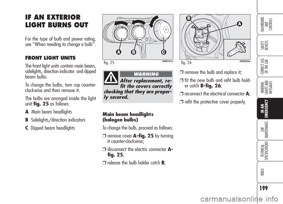
EMERGENCYMain beam headlights
(halogen bulbs)
To change the bulb, proceed as follows:
❒remove cover A-fig. 25by turning
it counter-clockwise;
❒disconnect the electric connectorA-
fig. 25;
❒release the bulb holder catch B;
IF AN EXTERIOR
LIGHT BURNS OUT
For the type of bulb and power rating,
see “When needing to change a bulb”.
FRONT LIGHT UNITS
The front light units contain main beam,
sidelights, direction indicator and dipped
beam bulbs.
To change the bulbs, turn cap counter-
clockwise and then remove it.
The bulbs are arranged inside the light
unitfig. 25as follows:
AMain beam headlights
BSidelights/direction indicators
CDipped beam headlights
A0E0191mfig. 25
After replacement, re-
fit the covers correctly
checking that they are proper-
ly secured.
WARNING
A0E0223mfig. 26
❒remove the bulb and replace it;
❒fit the new bulb and refit bulb hold-
er catch B-fig. 26;
❒reconnect the electrical connector A;
❒refit the protective cover properly.
Page 229 of 299

227
SAFETY
DEVICES
WARNING
LIGHTS AND
MESSAGES
IN AN
EMERGENCY
TECHNICAL
SPECIFICATIONS
INDEX
CORRECT USE
OF THE CAR
DASHBOARD
AND
CONTROLS
CAR
MAINTENANCE
USE OF THE CAR
UNDER HEAVY
CONDITIONS
Should prevailing use of the car be un-
der one of the following specially heavy
conditions:
❒ trailer or caravan towing;
❒ dusty roads;
❒ short distances (less than 7-8 km)
and repeated with external temper-
atures below zero;
❒ frequently idling engines or long dis-
tance low speed driving (e.g.: door-
to-door deliveries) or in case of a long
term inactivity;
❒ urban routes;
carry out checks more frequently than
required on Service Schedule:
❒ check front disk brake pad conditions
and wear;
❒ check cleanness of bonnet and boot
locks and lever cleanness and lubri-
cation;
❒ sight inspect the conditions of: en-
gine, gearbox, transmission, pipes
and hoses (exhaust - fuel - brakes),
rubber parts (boots, sleeves, bushes,
etc.);
❒ check battery charge and fluid level
(electrolyte);
❒ visual check on various drive belt con-
ditions;
❒ change engine oil and oil filter, if re-
quired;
❒ check and replace pollen filter, if re-
quired;
❒ check and replace air cleaner, if re-
quired.
PERIODICAL CHECKS
Every 1,000 km or before long jour-
neys, check and top up if required:
❒engine coolant fluid level;
❒brake fluid level;
❒windscreen washer fluid level;
❒ tyre pressure and conditions.
❒ check light system operation (head-
lights, direction indicators, hazard
lights, etc.);
❒ check windscreen wiper/washer op-
eration and windscreen/rear window
blade position/wear;
Every 3,000 km check and top up if re-
quired: engine oil level.
You are recommended to use FL Se-
leniaproducts, designed and produced
specifically for Alfa Romeo cars (see
table “Capacities” in section “Techni-
cal specifications”).
Page 234 of 299

232
SAFETY
DEVICES
WARNING
LIGHTS AND
MESSAGES
IN AN
EMERGENCY
TECHNICAL
SPECIFICATIONS
INDEX
CORRECT USE
OF THE CAR
DASHBOARD
AND
CONTROLS
CAR
MAINTENANCE
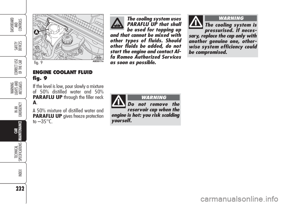
ENGINE COOLANT FLUID
fig. 9
If the level is low, pour slowly a mixture
of 50% distilled water and 50%
PARAFLU UPthrough the filler neck
A.
A 50% mixture of distilled water and
PARAFLU UP gives freeze protection
to –35°C.
A0E0017mfig. 9
The cooling system uses
PARAFLU UP that shall
be used for topping up
and that cannot be mixed with
other types of fluids. Should
other fluids be added, do not
start the engine and contact Al-
fa Romeo Authorized Services
as soon as possible.
Do not remove the
reservoir cap when the
engine is hot: you risk scalding
yourself.
WARNING
The cooling system is
pressurised. If neces-
sary, replace the cap only with
another genuine one, other-
wise system efficiency could
be compromised.
WARNING
Page 235 of 299

233
SAFETY
DEVICES
WARNING
LIGHTS AND
MESSAGES
IN AN
EMERGENCY
TECHNICAL
SPECIFICATIONS
INDEX
CORRECT USE
OF THE CAR
DASHBOARD
AND
CONTROLS
CAR
MAINTENANCE
WINDSCREEN/HEADLIGHT
WASHER FLUID fig. 10
To top up, remove the cap Aand then
pour a mixture of water and TUTELA
PROFESSIONAL SC 35, in the fol-
lowing concentrations:
❒30%TUTELA PROFESSIONAL
SC 35and 70% water in summer;
❒50%TUTELA PROFESSIONAL
SC 35 and 50% water in winter.
In case of temperatures below –20°C,
use undiluted TUTELA PROFES-
SIONAL SC 35.
A0E0029mfig. 10
Do not travel with the
windscreen washer
reservoir empty. The wind-
screen washer is fundamental
for improving visibility.
WARNING
Certain commercial ad-
ditives for windscreen
washers are inflammable. The
engine compartment contains
hot components which may set
it on fire.
WARNING
Page 236 of 299

234
SAFETY
DEVICES
WARNING
LIGHTS AND
MESSAGES
IN AN
EMERGENCY
TECHNICAL
SPECIFICATIONS
INDEX
CORRECT USE
OF THE CAR
DASHBOARD
AND
CONTROLS
CAR
MAINTENANCE
POWER STEERING FLUID
fig. 11-12
Check that the fluid level in the reservoir
is at maximum level: this operation shall
be carried out with the car on level sur-
face, engine not running and cold.
Check that the fluid level is at the MAX
mark on the reservoir or at the top mark
(maximum level) shown on the dipstick
under the reservoir cap.
A0E0027mfig. 11 1.9 JTS - 2.2 JTS - 2.4 JTDMversions
A0E0234mfig. 12 3.2 JTS -
1.9 JTDM8V- 1.9 JTDM16Vversions
If the fluid level in the reservoir is below
the specified level, top up as follows:
❒start the engine and wait until the flu-
id level in the reservoir has stabilized;
❒with the engine started, turn repeat-
edly the steering wheel fully right-
wards and leftwards;
❒top up until reaching the MAXmark
then refit the cap.IMPORTANTFor this operation it is
however recommended to always con-
tact Alfa Romeo Authorized Services.
Do not allow the pow-
er steering fluid to
touch the hot parts of the en-
gine: it is inflammable.
WARNING
Page 237 of 299

235
SAFETY
DEVICES
WARNING
LIGHTS AND
MESSAGES
IN AN
EMERGENCY
TECHNICAL
SPECIFICATIONS
INDEX
CORRECT USE
OF THE CAR
DASHBOARD
AND
CONTROLS
CAR
MAINTENANCE
BRAKE FLUID fig. 13
Unscrew cap Aand check that the flu-
id level in the reservoir is at maximum.
Fluid level in the reservoir shall not ex-
ceed the MAXmark.
IMPORTANTFor this operation it is
however recommended to always con-
tact Alfa Romeo Authorized Services.
A0E0016mfig. 13
Make sure that the high-
ly corrosive brake fluid
does not drip onto the
paintwork. If it does, wash it off
immediately with water.From time to time, check the instrument
panel warning light
x: pressing on cap
A(with key fitted into the ignition de-
vice) the warning light shall turn on.
IMPORTANTBrake fluid absorbs
moisture. For this reason, if the car is
mainly used in areas with a high degree
of atmospheric humidity, the fluid should
be replaced at more frequent intervals
than specified in the Service schedule.