cap Alfa Romeo 159 2006 Owner handbook (in English)
[x] Cancel search | Manufacturer: ALFA ROMEO, Model Year: 2006, Model line: 159, Model: Alfa Romeo 159 2006Pages: 299, PDF Size: 4.64 MB
Page 13 of 299
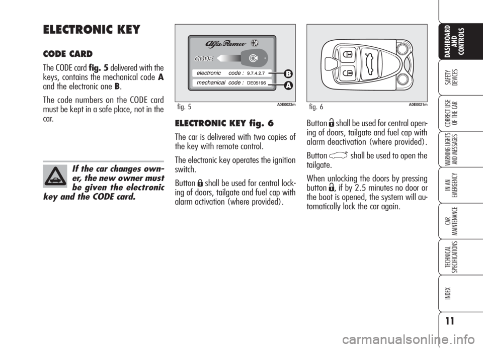
ButtonËshall be used for central open-
ing of doors, tailgate and fuel cap with
alarm deactivation (where provided).
Button
`shall be used to open the
tailgate.
When unlocking the doors by pressing
button
Ë, if by 2.5 minutes no door or
the boot is opened, the system will au-
tomatically lock the car again.
ELECTRONIC KEY fig. 6
The car is delivered with two copies of
the key with remote control.
The electronic key operates the ignition
switch.
Button
Áshall be used for central lock-
ing of doors, tailgate and fuel cap with
alarm activation (where provided).
ELECTRONIC KEY
CODE CARD
The CODE card fig. 5delivered with the
keys, contains the mechanical codeA
and the electronic one B.
The code numbers on the CODE card
must be kept in a safe place, not in the
car.
11
SAFETY
DEVICES
WARNING LIGHTS
AND MESSAGES
IN AN
EMERGENCY
CAR
MAINTENANCE
TECHNICAL
SPECIFICATIONS
INDEX
DASHBOARD
AND
CONTROLS
CORRECT USE
OF THE CAR
A0E0023mfig. 5
If the car changes own-
er, the new owner must
be given the electronic
key and the CODE card.
A0E0021mfig. 6
Page 18 of 299
16
SAFETY
DEVICES
WARNING LIGHTS
AND MESSAGES
IN AN
EMERGENCY
CAR
MAINTENANCE
TECHNICAL
SPECIFICATIONS
INDEX
DASHBOARD
AND
CONTROLS
CORRECT USE
OF THE CAR
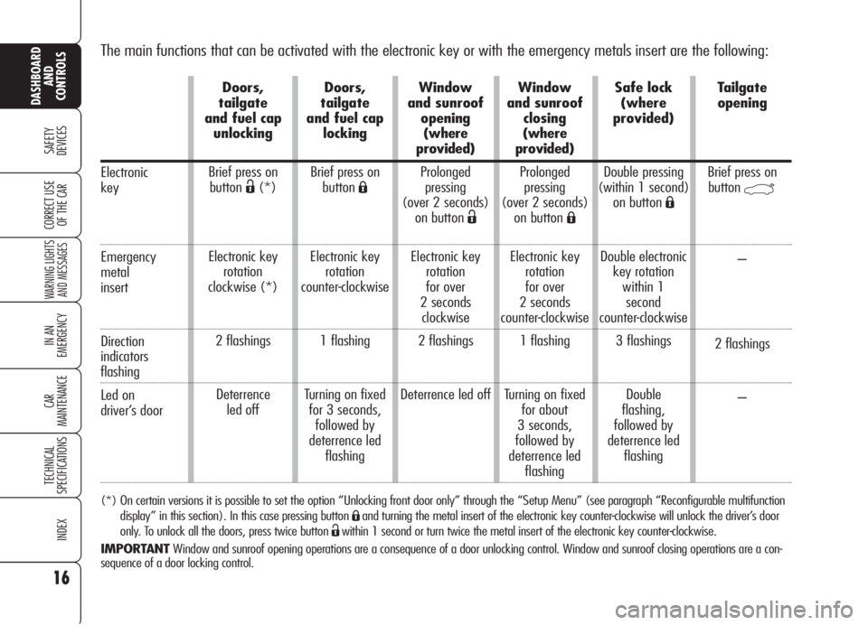
The main functions that can be activated with the electronic key or with the emergency metals insert are the following:
(*) On certain versions it is possible to set the option “Unlocking front door only” through the “Setup Menu” (see paragraph “Reconfigurable multifunction
display” in this section). In this case pressing button
Áand turning the metal insert of the electronic key counter-clockwise will unlock the driver’s door
only. To unlock all the doors, press twice button
Ëwithin 1 second or turn twice the metal insert of the electronic key counter-clockwise.
IMPORTANTWindow and sunroof opening operations are a consequence of a door unlocking control. Window and sunroof closing operations are a con-
sequence of a door locking control.
Electronic
key
Emergency
metal
insert
Direction
indicators
flashing
Led on
driver’s door
Doors,
tailgate
and fuel cap
unlocking
Brief press on
button
Ë(*)
Electronic key
rotation
clockwise (*)
2 flashings
Deterrence
led offDoors,
tailgate
and fuel cap
locking
Brief press on
buttonÁ
Electronic key
rotation
counter-clockwise
1 flashing
Turning on fixed
for 3 seconds,
followed by
deterrence led
flashingWindow
and sunroof
opening
(where
provided)
Prolonged
pressing
(over 2 seconds)
on button
Ë
Electronic key
rotation
for over
2 seconds
clockwise
2 flashings
Deterrence led offWindow
and sunroof
closing
(where
provided)
Prolonged
pressing
(over 2 seconds)
on button
Á
Electronic key
rotation
for over
2 seconds
counter-clockwise
1 flashing
Turning on fixed
for about
3 seconds,
followed by
deterrence led
flashingSafe lock
(where
provided)
Double pressing
(within 1 second)
on button
Á
Double electronic
key rotation
within 1
second
counter-clockwise
3 flashings
Double
flashing,
followed by
deterrence led
flashingTailgate
opening
Brief press on
button
`
–
2 flashings
–
Page 60 of 299
58
SAFETY
DEVICES
WARNING
LIGHTS AND
MESSAGES
IN AN
EMERGENCY
CAR
MAINTENANCE
TECHNICAL
SPECIFICATIONS
INDEX
CORRECT USE
OF THE CAR
DASHBOARD
AND
CONTROLS
To guarantee perfect
and regular sensor op-
eration do not apply
stickers in the “monitoring”
area between sensor and wind-
screen. Keep windscreen and
sensor clean and avoid to accu-
mulate dust or other sub-
stances.
AUTOMATIC TWO-/
THREE-ZONE
CLIMATE CONTROL
SYSTEM
(where provided)
DESCRIPTION
The car is fitted with a two-/three-zone
climate control system which makes it
possible to separately adjust the air tem-
perature in the two/three passenger’s
compartment areas to reach the required
comfort.
For top quality temperature control in
the two/three areas of the passenger's
compartment, the system is fitted with
external temperature sensor, passen-
ger's compartment temperature sensor
and two-side sun radiation sensor.
The climate control system automatically
controls and adjusts the following pa-
rameters and functions:
❒air temperature at driver/passengers
vents;
❒fan speed;
❒air distribution at driver/passenger
vents;
❒compressor activation;
❒air recirculation.
The following parameters and functions
can be set or changed manually:
❒required temperature;
❒fan speed;
❒air distribution on seven levels ;
❒compressor on/off;
❒window demisting/defrosting;
❒air recirculation;
❒one-zone function.
The system is fitted with AQS (Air Qual-
ity System) sensor (where provided),
that turns on air recirculation automati-
cally when it detects the presence of out-
side polluted air (for example in queues
and tunnels).
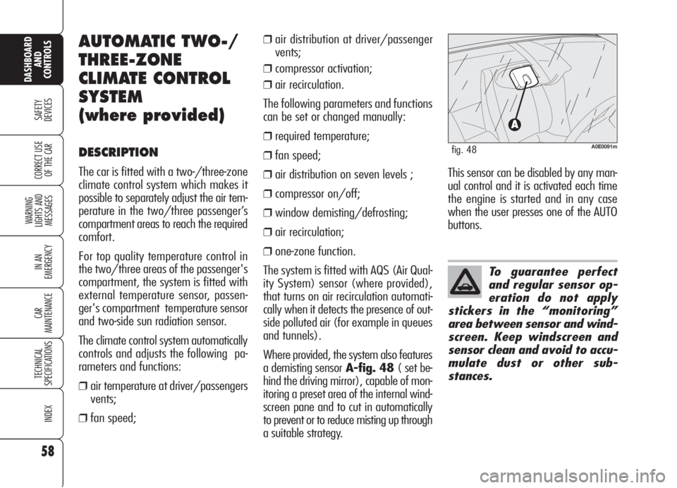
Where provided, the system also features
a demisting sensorA-fig. 48 ( set be-
hind the driving mirror), capable of mon-
itoring a preset area of the internal wind-
screen pane and to cut in automatically
to prevent or to reduce misting up through
a suitable strategy.
A0E0091mfig. 48
This sensor can be disabled by any man-
ual control and it is activated each time
the engine is started and in any case
when the user presses one of the AUTO
buttons.
Page 70 of 299

68
SAFETY
DEVICES
WARNING
LIGHTS AND
MESSAGES
IN AN
EMERGENCY
CAR
MAINTENANCE
TECHNICAL
SPECIFICATIONS
INDEX
CORRECT USE
OF THE CAR
DASHBOARD
AND
CONTROLS
POLLEN FILTER/ ACTIVATED
CARBON POLLEN FILTER
According to versions, the car can be fit-
ted with pollen filter or activated carbon
pollen filter (where provided). The filter
has the specific capability of admitting to
the passenger compartment purified air,
free from particles such as dust, pollen,
etc. The filtering action takes place un-
der all air inlet conditions and it is clear-
ly most effective with the windows shut.
Have the conditions of the filter checked
by Alfa Romeo Authorized Services at
least once a year, preferably at the on-
set of summer. If the car is used main-
ly in polluted or dusty areas it should be
checked and if necessary replaced at
shorter intervals than specified in the
Service Schedule (see section “Car
Maintenance”). AQS function (Air Quality
System) (where provided)
The AQS function turns on automatical-
ly air recirculation when it detects the
presence of polluted air (e.g. in queues
and tunnels).
IMPORTANTWith AQS function on,
after a preset time with recirculation on,
the compressor will enable outside air
inlet (for about 1 minute) to change air
inside the passenger compartment, re-
gardless of outside air pollution level.
IMPORTANTThe AQS function is dis-
abled when the outside temperature is
cold to prevent window misting up. To
reactivate this function, press button
v. Led “A” on button vwill
turn on to indicate that the function is
on.
Failure to replace the fil-
ter may considerably re-
duce the effectiveness of
the climate control system up to
blocking the air flow from the
outlets and vents.
In certain weather con-
ditions (e.g. outside
temperature around
0°C) and with automatic air re-
circulation control on, mist may
form on the windows. In this
case press button vto
switch off recirculation and if
necessary press button + to in-
crease the flow of air to the
windscreen.
With the outside tem-
perature below -1°C the
climate control compres-
sor is unable to work. It is
therefore inadvisable to use the
inside air recirculation function
with low outside temperature
as windows may mist over
quickly.
Page 119 of 299
117
SAFETY
DEVICES
WARNING
LIGHTS AND
MESSAGES
IN AN
EMERGENCY
CAR
MAINTENANCE
TECHNICAL
SPECIFICATIONS
INDEX
CORRECT USE
OF THE CAR
DASHBOARD
AND
CONTROLS
RADIO TRANSMITTERS AND
CELLULAR TELEPHONES
Radio transceiver equipment (e.g.: e-
tacs mobile phones, HAM radio systems
and the like) shall not be used inside the
car unless a separate aerial is mounted
outside the car.
The use of these devices inside the pas-
senger compartment (without external
aerial) may cause electrical systems
equipping the car to malfunction. This
could compromise car safety in addition
to constituting a potential hazard for the
passengers.
In addition, transmission and reception
of these devices may be affected by the
shielding effect of the car body.
As concerns the use of mobile phones
(GSM, GPRS, UMTS) provided with of-
ficial EC approval, strictly comply with
the instructions given by the mobile
phone manufacturer.
ACCESSORIES
PURCHASED
BY THE OWNER
If after buying the car, you decide to in-
stall electrical accessories that require a
permanent electric supply (alarm, satel-
lite antitheft system, etc.) or accessories
that in any case burden the electric sup-
ply, contact Alfa Romeo Authorized Ser-
vices, whose qualified personnel, besides
suggesting the most suitable devices be-
longing to Lineaccessori Alfa Romeo, will
also evaluate the overall electric absorp-
tion, checking whether the car’s electric
system is able to withstand the load re-
quired, or whether it needs to be inte-
grated with a more powerful battery.
Take care when fitting
additional spoilers, al-
loy rims and non-standard
wheel caps: they might reduce
ventilation of the brakes, thus
their efficiency, during abrupt
and repeated braking, or long
downhill slopes. Make sure
that nothing (mats, etc.) gets
in the way of the pedals when
they are pushed down.
WARNING
Page 124 of 299

122
SAFETY
DEVICES
WARNING
LIGHTS AND
MESSAGES
IN AN
EMERGENCY
CAR
MAINTENANCE
TECHNICAL
SPECIFICATIONS
INDEX
CORRECT USE
OF THE CAR
DASHBOARD
AND
CONTROLS
The car can be equipped with the
T.P.M.S. (Tyre Pressure Monitoring Sys-
tem). This system consists of a radio-fre-
quency sensor, installed on each wheel
(on the rim inside the tyre) that sends
pressure information to the control unit.IMPORTANT NOTES
Failure indications will not be stored and
therefore will not be displayed when
turning the engine off and on again. If
failure persists, the control unit will send
warning indications to the instrument
panel only after a few seconds when the
car is moving.
Tyre pressure should be checked with
tyres cold. Should it become necessary
for whatever reason to check pressure
with hot tyres, do not reduce pressure
although it is higher than the prescribed
value but repeat the check when tyres
are cold (see section “Wheels” in sec-
tion “Technical Specifications”).
TYRE PRESSURE MONITORING SYSTEM -
T.P.M.S. (where provided)
The T.P.M.S. does not
exempt the driver from
checking tyre pressure, includ-
ing the space-saver spare
wheel (where provided) at
regular intervals.
WARNING
T.P.M.S. cannot indicate sudden tyre
pressure drops (e.g.: tyre burst). In this
event, brake the car cautiously and
avoid sudden steering.
The T.P.M.S. system requires special
equipment. Consult Alfa Romeo Autho-
rized Services to know what type of ac-
cessories are compatible with the sys-
tem (wheels, wheel caps, etc.). Using
other accessories could cause system
malfunctioning. Due to inflation valve
special characteristics, use only tyre re-
pair sealants approved by Alfa Romeo;
other sealants could cause system mal-
functioning.
Page 128 of 299

126
SAFETY
DEVICES
WARNING
LIGHTS AND
MESSAGES
IN AN
EMERGENCY
CAR
MAINTENANCE
TECHNICAL
SPECIFICATIONS
INDEX
CORRECT USE
OF THE CAR
DASHBOARD
AND
CONTROLS
EMERGENCY OPENING OF
THE FUEL FILLER CAP
In case of failure, the fuel filler cap can
be opened by pulling string set on the
right side of the boot fig. 110.
A0E0130mfig. 110
FUEL FILLER CAP
The fuel filler cap is unlocked when cen-
tral door locking is off and it is auto-
matically locked when activating the
central door locking. To open the fuel
filler cap, operate as shown by the ar-
row infig. 108.
The fuel filler cap is A-fig. 109 fitted
with an antiloss device Bwhich fastens
it to the flap Cso it cannot be mislaid.
A0E0159mfig. 108A0E0160mfig. 109
Do not put naked
flames or lighted ciga-
rettes near the fuel filler hole
as there is danger of fire. Do
not bend too close to the hole
either so as not to breathe in
harmful vapours.
WARNING
When refuelling, position the cap on the
device inside the flap as shown in the
figure.
IMPORTANTThe sealing of the tank
may cause light pressurising in the tank.
A little breathing off, while slackening
the cap, is absolutely normal.
Page 161 of 299

159
SAFETY
DEVICES
WARNING
LIGHTS AND
MESSAGES
IN AN
EMERGENCY
CAR
MAINTENANCE
TECHNICAL
SPECIFICATIONS
INDEX
DASHBOARD
AND
CONTROLS
CORRECT USE
OF THE CAR
Engage a low gear when driving down-
hill, rather than constantly using the
brake.
The weight the trailer exerts on the car
tow hook reduces by the same amount
the actual car loading capacity. To make
sure the maximum towable weight is
not exceeded (given in the log book)
account should be taken of the fully
laden trailer, including accessories and
personal belongings.
Do not exceed the speed limits of the
country you are driving in. In any case
do not exceed 100 km/h.TOWING TRAILERS
IMPORTANT NOTES
For towing caravans or trailers the car
must be fitted with a certified tow hook
and an adequate electric system. In-
stallation should be carried out by spe-
cialised personnel who release a special
document for circulation on the road.
Install any specific and/or additional
rear-view mirrors as specified by law.
Remember that when towing a trailer,
steep hills are harder to climb, the brak-
ing spaces increase and overtaking takes
longer depending on the overall weight.
The ABS system with
which the car may be
fitted does not control the
trailer braking system. Drive
with extreme care on slippery
roadbeds.
WARNING
Under no circumstances
should the car brake
system be altered to control
the trailer brake. The trailer
braking system must be fully
independent of the car hy-
draulic system.
WARNING
Page 171 of 299
169
SAFETY
DEVICES
IN AN
EMERGENCY
CAR
MAINTENANCE
TECHNICAL
SPECIFICATIONS
INDEX
CORRECT USE
OF THE CAR
DASHBOARD
AND
CONTROLS
WARNING
LIGHTS AND
MESSAGES
–Car heavy duty(e.g.: towing trail-
er uphill or fully laden car): decrease
speed, if the warning light stays on, stop
the car. Wait for 2 or 3 minutes leaving
the engine on and slightly accelerated to
further activate the circulation of the
coolant fluid, then switch the engine off.
IMPORTANTUnder severe use of the
car, keep the engine on and slightly ac-
celerated for few minutes before switch-
ing it off.
Warning light Findi-
cates also warning light
¬failures. This is indicated by
intermittent flashing, over 4
seconds, of warning light
F. In
this event warning light
¬could
not indicate safety system fail-
ures. Contact Alfa Romeo Au-
thorized Services to have the
system checked immediately.
WARNINGENGINE COOLANT
HIGH TEMPERATURE
(red)
Fitting the key into the ignition device,
the warning light (set on engine coolant
gauge) turns on but it shall go off after
a few seconds.
The warning light turns on (on certain
versions a dedicated message is dis-
played) to indicate engine overheating.
If the warning light comes on, proceed
as follows:
–Normal driving conditions: stop
the car, switch off the engine and check
whether the water level in the reservoir
is not below the MINmarl. Otherwise
wait for few seconds to allow engine
cooling, then open slowly and carefully
the cap, top up coolant and check
whether its level is falling between MIN
andMAXmarks in the reservoir. Check
visually any leak. If when restarting the
warning light comes on again, contact
Alfa Romeo Authorized Services .
u
With engine hot, do not
remove the cap: risk of
burnt.
WARNING
Page 184 of 299
182
SAFETY
DEVICES
WARNING
LIGHTS AND
MESSAGES
CAR
MAINTENANCE
TECHNICAL
SPECIFICATIONS
INDEX
CORRECT USE
OF THE CAR
DASHBOARD
AND
CONTROLS
IN AN
EMERGENCY
JUMP STARTING
If the battery is flat, it is possible to start
the engine using an auxiliary battery
with the same capacity or a little high-
er than the flat one.
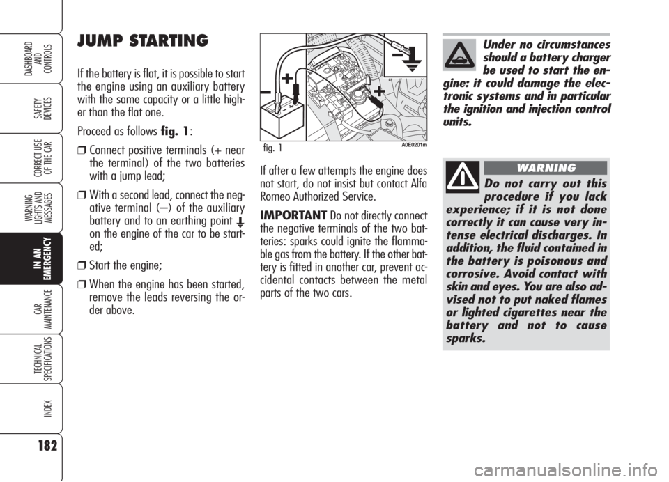
Proceed as follows fig. 1:
❒ Connect positive terminals (+ near
the terminal) of the two batteries
with a jump lead;
❒ With a second lead, connect the neg-
ative terminal (–) of the auxiliary
battery and to an earthing point
E
on the engine of the car to be start-
ed;
❒Start the engine;
❒When the engine has been started,
remove the leads reversing the or-
der above.If after a few attempts the engine does
not start, do not insist but contact Alfa
Romeo Authorized Service.
IMPORTANTDo not directly connect
the negative terminals of the two bat-
teries: sparks could ignite the flamma-
ble gas from the battery. If the other bat-
tery is fitted in another car, prevent ac-
cidental contacts between the metal
parts of the two cars.
Under no circumstances
should a battery charger
be used to start the en-
gine: it could damage the elec-
tronic systems and in particular
the ignition and injection control
units.
Do not carry out this
procedure if you lack
experience; if it is not done
correctly it can cause very in-
tense electrical discharges. In
addition, the fluid contained in
the battery is poisonous and
corrosive. Avoid contact with
skin and eyes. You are also ad-
vised not to put naked flames
or lighted cigarettes near the
battery and not to cause
sparks.
WARNING
A0E0201mfig. 1